Table of Contents
Advertisement
Quick Links
Advertisement
Table of Contents

Related Manuals for Renault ALASKAN 2020


Summary of Contents for Renault ALASKAN 2020
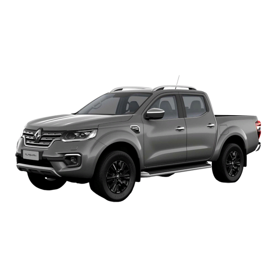
- Page 1 Renault ALASKAN Vehicle user manual...
- Page 2 Benefit from cutting-edge technology born out of competition to ensure the performance and longevity of your Renault thanks to wide range of engine lubricants developed specially by Renault and Castrol. your Renault thanks to wide range of engine lubricants developed specially by Renault and Castrol.
- Page 3 CAUTION All information, specifications and illustrations in this handbook are those in effect at the time of printing. RENAULT reserves the right to change specifica- Indicates the presence of a hazard that could cause minor or moderate per- tions or designs at any time without notice and without obligation.
- Page 4 Air bag warning labels: This symbol means “Do not do this” or “Do not let this happen”. “NEVER use a rearward facing child restraint on a seat protected by an ACTIVE AIRBAG in front of it, DEATH or SERIOUS INJURY to the CHILD can occur.” Arrows in an illustration that are similar to these point to the front of the vehicle.
- Page 5 BATTERY DISPOSAL CAUTION An improperly disposed battery can harm the environment. Always confirm local regulations for battery disposal. Examples of the batteries that the vehicle contains: • Vehicle battery • Remote controller battery (for Remote Control Key and/or Remote keyless entry system) •...
-
Page 7: Table Of Contents
Contents Illustrated table of contents Safety — seats, seat belts and supplemental restraint system Instruments and controls Pre-driving checks and adjustments Display screen, heater and air conditioner, and audio system Starting and driving In case of emergency Appearance and care Maintenance and do-it-yourself Technical information Index... - Page 9 Illustrated table of contents Illustrated table of contents Seats, seat belts and Supplemental Restraint Right-Hand Drive (RHD) model ..........System (SRS)....................Instrument panel ..................Exterior front ....................Left-Hand Drive (LHD) model ............Exterior rear ..................... Right-Hand Drive (RHD) model ..........Passenger compartment...............
-
Page 10: Seats, Seat Belts And Supplemental Restraint System (Srs)
SEATS, SEAT BELTS AND SUPPLEMENTAL RESTRAINT SYSTEM (SRS) where fitted NIC2797 Supplemental front-impact air bags* (P. 1-42) Child restraint anchor point* (for top tether strap child restraint) (P. 1-33) Front passenger air bag switch* (P. 1-50) Rear seats* (P. 1-17) Supplemental curtain side-impact air bags* (P. -
Page 11: Exterior Front
EXTERIOR FRONT Side turn signal lights — Bulb replacement (P. 8-283) 10. Tyres — Tyres and wheels (P. 8-286) — Flat tyre (P. 6-238) — Specifications (P. 9-292) — Four-Wheel Drive (4WD)*1 (P. 5-217) 11. Headlights and turn signal lights —... -
Page 12: Exterior Rear
EXTERIOR REAR NIC3081 Rear window defogger* (P. 2-83) Rear combination lights (bulb replacement) (P. 8-283) High-mounted stop light* (P. 5-234) Number plate lights (bulb replacement) Antenna* (P. 4-149) (P. 8-283) AdBlue filler lid (P. 3-114) Parking sensor (sonar)* (P. 5-230) Rear view camera* where fitted —... -
Page 13: Passenger Compartment
PASSENGER COMPARTMENT 11. Door armrest — Power window controls* (P. 2-85) — Power door lock switch (driver's door)* (P. 3-98) — Outside rearview mirror remote control switch (driver's door)* (P. 3-120) where fitted NIC2792 Inside rearview mirror (P. 3-118) Map lights (P. 2-92) Sunglasses holder (P. -
Page 14: Cockpit
COCKPIT Wiper and washer switch (P. 2-82) Steering-wheel-mounted controls* (right side) — Cruise control system* (P. 5-224) — Speed limiter system* (P. 5-226) — Hands-Free Phone System switch* (P. 4-182) Shift lever — Automatic Transmission (AT) (P. 5-204) — Manual Transmission (MT) (P. 5-207) 10. -
Page 15: Right-Hand Drive (Rhd) Model
Headlight, fog light, and turn signal switch — Headlight (P. 2-79) — Fog light* (P. 2-81) — Turn signal (P. 2-81) Twin trip odometer (P. 2-70) <TRIP RESET> switch for twin trip odometer (P. 2-70) Instrument brightness control switch (P. 2-56) 10. -
Page 16: Instrument Panel
INSTRUMENT PANEL 10. USB (Universal Serial Bus) connection port (P. 4-150)/iPod connection port (P. 4-159) — Auxiliary (AUX) input jack (P. 4-150) 11. Power door lock switch* (P. 3-98) 12. Hill descent control switch* (P. 5-223) 13. Parking brake — Operation (P. 3-121) —... -
Page 17: Right-Hand Drive (Rhd) Model
Ignition switch (models without Remote Control Key system) (P. 5-199) 10. Steering wheel — Horn (P. 2-84) — Driver’s supplemental front-impact air bag* (P. 1-42) — Power steering system (P. 5-233) 11. USB (Universal Serial Bus) connection port (P. 4-150)/iPod connection port (P. 4-159) —... -
Page 18: Meters And Gauges
METERS AND GAUGES NIC2681 Tachometer (P. 2-55) — Instrument brightness control (P. 2-56) — Automatic Transmission (AT) position indica- Warning and indicator lights (P. 2-55) tor (AT model) (P. 2-77, P. 5-204) Vehicle information display (P. 2-65) Speedometer (P. 2-54) —... -
Page 19: Engine Compartment
ENGINE COMPARTMENT 11. Power steering fluid reservoir (P. 8-267) For Manual Transmission (MT) model *2: The layout illustrated is for the Left-Hand Drive (LHD) model. On the Right-Hand Drive (RHD) model, brake (and clutch) fluid reservoir is located on the opposite side. NIC3082 M9T 2.3DCI ENGINE Battery (P. - Page 20 NOTE Illustrated table of contents...
-
Page 21: Safety - Seats, Seat Belts And Supplemental Restraint System
Safety — seats, seat belts and Safety — seats, seat belts and supplemental restraint system supplemental restraint system Seats........................14 Child restraints....................26 Front seats....................14 Precautions on child restraint usage........26 Rear seats (Double Cab model)..........Universal child restraints for front seat and Head restraints .................... - Page 22 SEATS FRONT SEATS WARNING Do not adjust the driver’s seat while driving so that full attention may be given to vehicle operation. Manual seat adjustment (where fitted) WARNING SSS0133AZ After adjusting a seat, gently shake the seat to • confirm that the seat is locked securely. If the seat To help avoid risk of injury or death through is not locked securely, it may move suddenly and WARNING...
- Page 23 Operating tips: • The power seat motor has an auto-reset over- load protection circuit. If the motor stops during the seat adjustment, wait 30 seconds, then re- activate the switch. • To avoid discharge of the battery, do not oper- ate the power seats for a long period of time when the engine is not running.
- Page 24 JVR0054XZ JVR0056XZ Forward and backward: Lumbar support: ➀ Move the adjusting switch forward or backward The lumbar support feature provides lower back to the desired position. support to the driver. ➀ ➁ Push each side of the adjusting switch Reclining: ➁...
- Page 25 Heated seats (where fitted) REAR SEATS (Double Cab model) 3. To turn off the heater, return the switch to the level position. Make sure the indicator light turns Folding off. The heater is controlled by a thermostat, auto- matically turning the heater on and off. The indi- cator light will remain on as long as the switch is When the vehicle's interior is warmed be sure to turn off the switch.
- Page 26 HEAD RESTRAINTS • If the head restraint has been removed, ensure WARNING WARNING • that it is reinstalled and locked in place before Never allow anyone to ride on the rear seats Head restraints supplement the other vehicle riding in that designated seating position. when they are in the fold-up position.
- Page 27 NON-ADJUSTABLE HEAD ADJUST Use the following procedure to remove the head restraint. RESTRAINT 1. Pull the head restraint up to the highest position. 2. Push and hold the lock knob. 3. Remove the head restraint from the seat. 4. Store the head restraint properly in a secure place so it is not loose in the vehicle.
- Page 28 Raise and/or the severity of injury may be greatly reduced. RENAULT strongly encourages you and all of your passengers to buckle up every time you drive, even if your seating position includes the supplemental air bag systems.
- Page 29 SSS0134AZ SSS0014Z SSS0136AZ SSS0016Z WARNING • Seat belts are designed to bear upon the bony structure of the body, and should be worn low across the front of the pelvis or the pelvis, chest and shoulders, as applicable; wearing the lap section of the belt across the abdomi- nal area must be avoided.
- Page 30 • No modifications or additions should be made RENAULT recommends that infants and small chil- by the user which will either prevent the seat dren be seated in a child restraint system. You...
- Page 31 Large children PREGNANT WOMEN THREE-POINT TYPE SEAT BELTS RENAULT recommends that pregnant women use Fastening seat belts WARNING seat belts. The seat belt should be worn snug, and • Never allow children to stand or kneel on any always position the lap belt as low as possible seats.
- Page 32 ➀ Shoulder belt height adjustment (for 2. Slowly pull the seat belt out of the retractor and To adjust, pull on the release button and move ➁ insert the tongue into the buckle until you hear the shoulder belt anchor to the proper position front seats) and feel the latch engage.
- Page 33 TWO-POINT TYPE SEAT BELTS SEAT BELT MAINTENANCE (where fitted) Periodically check that the seat belt and all the metal components, such as buckles, tongues, re- Fastening seat belts tractors, flexible wires and anchors, work properly. If loose parts, deterioration, cuts or other damage on WARNING the seat belt webbing is found, the entire seat belt Every person who drives or rides in this vehicle...
- Page 34 • • RENAULT recommends that the child restraint Adjustable seatbacks should be positioned to WARNING system be installed in the rear seat. According fit a child restraint system, but as upright as •...
- Page 35 • stop or accident. Check the child restraint in your vehicle to be sure it is compatible with vehicle's retention sys- RENAULT recommends that infants and small chil- tem. dren be seated in a child restraint system. You • Refer to the tables later in this section for a list of...
- Page 36 JVR0373XZ Child safety seat categories II and III Safety — seats, seat belts and supplemental restraint system...
- Page 37 Child restraint installation using the vehicle's seat belt The following restriction is applied when using child restraints varying by infants weight and installation position. Seating position Mass group Front passenger seat Front passenger seat Second row outer seat Second row centre seat *4 (Air bag ON) (Air bag OFF) <10 kg...
- Page 38 Child restraint installation using ISOFIX The following restriction is applied when using child restraints varying by infant's weight and installation position. Seating position Mass group Front passenger seat Front passenger seat Second row outer seat Second row centre seat (Air bag ON) (Air bag OFF) ISO/L1 Carry-cot...
- Page 39 Child restraint installation using i-Size ISOFIX The following restriction is applied when using child restraints varying by infant's weight and installation position. Seating position Front passenger seat Front passenger seat Second row outer seat Second row centre seat (Air bag ON) (Air bag OFF) i-Size child restraint systems i-U *1,*2...
- Page 40 ISOFIX AND I-SIZE CHILD RESTRAINT ISOFIX LOWER ANCHOR POINT LOCATIONS (Type B) (where fitted) SYSTEM (for second row seats) Your vehicle is equipped with special anchor points that are used with ISOFIX and i-Size child restraint systems. ISOFIX LOWER ANCHOR POINT LOCATIONS (Type A) (where fitted) NPA1526 i-Size ISOFIX cover removal...
- Page 41 ISOFIX and i-Size child restraints include two rigid erly installed using the damaged anchorage, and attachments that can be connected to two anchors a child could be seriously injured or killed in a located in the seat. With this system, you do not collision.
- Page 42 • 3. On the rear left and right seat simultaneous Do not secure a child restraint in the centre use: rear seating position using the ISOFIX lower anchors. The child restraint will not be secured 1) Follow steps 1 to 3 for each individual seat properly.
- Page 43 Installation on rear outboard seats restraint with your knee to compress the vehicle seat cushion and seatback. Adjustable seatbacks Front-facing child restraints: should be positioned to ensure full contact be- Be sure to follow the child restraint manufacturer's tween child restraint and seatback. instructions for the proper use of your child 6.
- Page 44 CHILD RESTRAINT INSTALLATION Rear-facing child restraints: 4. Shorten the rigid attachment to have the child restraint firmly tightened. To compress the ve- Be sure to follow the child restraint manufacturer's USING THREE-POINT TYPE SEAT hicle seat cushion and seatback, firmly press instructions for the proper use of your child BELT ➃...
- Page 45 4. Remove any additional slack from the seat belt; Rear-facing child restraint: ➂ ➃ press downward and rearward firmly in the Be sure to follow the manufacturer’s instructions centre of the child restraint with your knee to for the proper use of your child restraint. Follow compress the vehicle seat cushion and seatback these steps to install a rear-facing child restraint on while pulling up on the seat belt.
- Page 46 3. To prevent slack in the seat belt webbing, it is 5. Test the child restraint before you place the child ➄ necessary to secure the seat belt in place with in it . Push the child restraint from side to side locking devices attached to the child restraint.
- Page 47 • The front passenger air bag can be turned off with RENAULT recommends that a child restraint be the front passenger air bag switch A located inside installed on the rear seat (Double Cab mod- the glove box.
- Page 48 ➁ 2. Move the seat to the rearmost position ➂ 3. Remove the head restraint when a forward facing child restraint is to be fitted. Store the head restraint in a safe place. Be sure to reinstall the head restraint when- ever the child restraint is removed (see “Head restraints”...
- Page 49 8. Check to make sure that the child restraint is 3. Adjust the head restraint to its highest position ➂ properly secured prior to each use. If the child . Remove it if it interferes with the child restraint restraint is loose, repeat steps 1 through 7. installation.
- Page 50 SUPPLEMENTAL RESTRAINT SYSTEM (SRS) (where fitted) PRECAUTIONS ON SUPPLEMENTAL Supplemental curtain side-impact air 6. Test the child restraint before you place the child in it. Push the child restraint from side to side and bag system (where fitted) RESTRAINT SYSTEM (SRS) tug it forward to make sure that it is held se- This system can help cushion the impact force to This Supplemental Restraint System (SRS) section...
- Page 51 mental front-impact air bag if you are up against it when it inflates. Always sit back against the seatback and as far away as prac- tical from the steering wheel or instrument panel. Always use the seat belts. • Keep hands on the outside of the steering wheel.
- Page 52 SSS0006Z SSS0008Z SSS0099Z SSS0007Z SSS0009Z SSS0100Z Safety — seats, seat belts and supplemental restraint system...
- Page 53 WARNING • Never let children ride unrestrained or extend their hands or face out of the window. Do not attempt to hold them in your lap or arms. Some examples of dangerous riding positions are shown in the illustrations. • Children may be severely injured or killed when the air bags inflate if they are not prop- erly restrained.
- Page 54 • Air bag warning labels When sitting in the rear seats, do not hold onto WARNING • the seatback of the front seats. If the supple- The supplemental side-impact air bags mental side-impact air bags and supplemen- (where fitted) and supplemental curtain side- tal curtain side-impact air bags inflate, you impact air bags (where fitted) ordinarily will may be seriously injured.
- Page 55 SRS air bag warning light SRS front-impact passenger air bag: Under these conditions, the air bag and/or pre-ten- ➀ sioner seat belt system may not operate properly. The warning label is located on the sun visor. They must be checked and repaired. Contact an ap- “NEVER use a rearward facing child restraint on a proved dealer or qualified workshop immediately.
- Page 56 WARNING • Do not place any objects on the steering wheel pad, on the instrument panel, under the steer- ing column and near the front door finishers and the front seats. Do not place any objects between any occupants and the steering wheel pad, on the instrument panel, and near the front door finishers and the front seats.
- Page 57 • Work on and around the supplemental air bag The supplemental front-impact air bag system is systems should be done by an approved designed to inflate in higher severity frontal colli- dealer or qualified workshop. The SRS wiring sions, although it may inflate if the forces in another should not be modified or disconnected.
- Page 58 The front passenger air bag status lights Front passenger air bag switch (where fitted): To turn on the front passenger air bag: are located on the instrument panel between The front passenger air bag can be turned off with 1. Place the ignition switch in the OFF position. the centre vents.
- Page 59 Supplemental side-impact air bag collisions. Vehicle damage (or lack of it) is not al- vice manual. Incorrect disposal procedures ways an indication of proper supplemental curtain could cause personal injury. system (where fitted) side-impact air bag system operation. The pre-tensioner is encased with the front seat PRE-TENSIONER SEAT BELT SYSTEM belt’s retractor and anchor.
- Page 60 The supplemental front-impact air bags and pre- tensioner seat belts (where fitted) are designed to activate on a one-time-only basis. As a reminder, unless the SRS air bag warning light is damaged, the SRS air bag warning light remains illuminated after inflation has occurred.
-
Page 61: Instruments And Controls
Instruments and controls Instruments and controls Meters and gauges..................54 Defogger switch (where fitted)............83 Speedometer and Fuel gauge ........... 54 Headlight cleaner (where fitted)............84 Tachometer and Engine coolant temperature Headlight cleaner switch (where fitted) ......84 gauge......................55 Horn ........................ - Page 62 METERS AND GAUGES Fuel gauge Odometer NOTE For an overview see “Meters and gauges” in the “0. Illustrated table of contents” section and see “Instrument panel” in the “0. Illustrated table of contents” section. The needle indicators may move slightly after the ignition switch is placed in the OFF position.
- Page 63 Odometer (models without colour TACHOMETER AND ENGINE The dte mode includes a low range warning fea- ture. If the fuel level is low, the warning is displayed display) COOLANT TEMPERATURE GAUGE on the screen. Odometer/twin trip odometer: When the fuel level drops even lower, the dte display The odometer/twin trip odometer is displayed will change to “———”.
- Page 64 INSTRUMENT BRIGHTNESS Push the + side of the switch to brighten the meter ➀ panel lights. The bar moves to the + side. CONTROL Push the - side of the switch to dim the lights. The Instrument brightness control button ➀...
- Page 65 WARNING LIGHTS, INDICATOR LIGHTS AND AUDIBLE REMINDERS Anti-lock Braking System (ABS) warn- Four-Wheel Drive (4WD) warning light ing light* (4WD model) Front passenger air bag status light Active Emergency Braking system Low fuel warning light warning light* Automatic Transmission (AT) check Low washer fluid warning light* Glow plug indicator light* warning light (AT model)
- Page 66 CHECKING LIGHTS Automatic Transmission (AT) If an ABS malfunction occurs, the anti-lock function is turned off. The brake system then operates nor- check warning light (AT model) With all doors closed, apply the parking brake, fas- mally, but without anti-lock assistance. (See “Anti- ten the seat belts and place the ignition switch in When the ignition switch is in the ON position, the lock Braking System (ABS)”...
- Page 67 For 4WD model: If the ATP warning light illumi- require greater pedal travel distance and Anti-lock Braking System (ABS) warning indicator (where fitted): nates with the shift lever in the P (Park) position, effort. shift the Four-Wheel Drive (4WD) mode switch to When the parking brake is released and the brake the 2WD, 4H or 4LO position again with the shift fluid level is sufficient, if both the brake warning light...
- Page 68 Electronic Stability Programme Stop the vehicle safely as soon as possible. Stop the CAUTION engine immediately and call an approved dealer or (ESP) warning light Do not continue driving if the alternator belt is qualified workshop. (where fitted) loose, broken or missing. When the ignition switch is in the ON position, the CAUTION •...
- Page 69 • • Malfunction warning light (red) When towing a trailer or driving uphill, reduce If the Four-Wheel Drive (4WD) warning light the vehicle speed as soon as safely possible to turns on when driving on dry hard surface (where fitted) decrease the engine coolant temperature.
- Page 70 • Supplemental Restraint System Release Parking Brake warning CAUTION • (SRS) air bag warning light Low fuel warning Continuing vehicle operation without properly • (where fitted) Door open warning draining could cause serious damage to the • When the ignition switch is in the ON position, the engine.
- Page 71 High beam indicator light When the rear differential lock is engaged with the economy, and damage to the engine control differential lock mode switch or the <4LO> position system, which may affect the vehicle’s war- is selected with the Four-Wheel Drive (4WD) mode ranty coverage.
- Page 72 Security indicator light AUDIBLE REMINDERS Light reminder chime (where fitted) The light reminder chime will sound if the driver’s Brake pad wear warning side door is opened and the headlight switch is in The security indicator light blinks when the ignition The disc brake pads have audible wear warnings.
- Page 73 VEHICLE INFORMATION DISPLAY • Back button Oil control system (where fitted) — “Oil control system (where fitted)” later in this section Press the BACK button to return to the previous dis- play screen or menu level, or to cancel the selection HOW TO USE THE VEHICLE if it is not completed.
- Page 74 • • [Driver Assistance] (where fitted) [Range] [12Hr/24Hr] (where fitted) Select this sub-menu to change the parking sen- Select this sub-menu to choose the clock for- Use the switches and the <ENTER> button sor (sonar) detection range to one of the follow- mat between 12-hour and 24-hour.
- Page 75 [Vehicle Settings] [ECO Drive Report] (where fitted): [Turn Indicator]: There are 2 items in the [ECO Drive Report] menu. Select this sub-menu to enable/disable the items The following sub-menus are available under the • described below to ON or OFF. [Vehicle Settings] menu.
- Page 76 • [Units] [AdBlue Status] [AdBlue Status]: You can use this option to check the level of fluid in [Service] (where fitted): The following items are available under the [Units] the AdBlue® tank. menu. Select this item to show the remaining distance un- •...
- Page 77 • Russian • Arabic Use the and the <ENTER> buttons to select and change the language of the vehicle informa- tion display. [Factory Reset] The settings in the vehicle information display can be reset back to the factory default. To reset the vehicle information display: 1.
- Page 78 TRIP COMPUTER 1. Car view [Home] The Car view [Home] screen can be selected when the driver does not want see any information on the trip computer screen. 2. [Speed] and [Average] NIC3093 Left Hand Drive (LHD) model NIC3083 Type A Switches for the trip computer (where fitted) are located on the instrument panel on either the left ➀...
- Page 79 3. [Trip] 4. [Fuel Economy] 6. Compass (where fitted) NIC3666 NIC2758 NIC2732 Trip [Distance] [Average] fuel consumption This display indicates the heading direction of the vehicle A as well as a compass rose B around the The trip odometer mode shows the total distance The average fuel consumption mode shows the av- vehicle representation.
- Page 80 10. [Settings] The audio mode shows the status of audio infor- The distance to empty (dte) feature A provides you mation. with an estimation of the distance that can be driven before refuelling. The dte is constantly being For more details, see “FM AM radio with compact calculated based on the amount of fuel in the fuel disc (CD) player (Type A)”...
- Page 81 Instruments and controls...
- Page 82 INDICATORS FOR OPERATION 1. Engine start operation indicator (where fitted for Automatic Transmission (AT) models) This indicator appears when the shift lever is in the P (Park) position. This indicator means that the engine will start by pushing the ignition switch with the brake pedal depressed.
- Page 83 4. No Key Detected warning To push the ignition switch to the OFF position, per- You cannot start the engine with an unregistered form the following procedure: key. Use the registered Remote Control Key. (where fitted) Shift to Park warning (Move the shift lever to P) See “Remote Control Key system (where fitted)”...
- Page 84 21. 4WD Error warning (where fitted) For more details and precautions on seat belt us- CAUTION age, see “Seat belts” in the “1. Safety — seats, seat This warning appears when the four wheel drive The oil level should be checked regularly using belts and supplemental restraint system”...
- Page 85 25. Time for a driver break? indicator 29. Parking Sensor Error warning (where fitted) This indicator appears when the set [Timer] alarm activates. You can set the time for up to 6 hours. This warning appears when the parking sensor (so- (See “Settings”...
- Page 86 OIL CONTROL SYSTEM 1. Distance to oil change – The oil replacement indicator is displayed in the vehicle information display. (where fitted) The distance to oil change is displayed if the dis- • The engine oil should be changed before the tance to oil change is less than 1,500 km (930 miles).
- Page 87 CLOCK AND OUTSIDE AIR on various signs or billboards. TEMPERATURE (where fitted) NIC2765 RENAULT recommends that you consult the local regulations concerning the use of lights. AUTO position JVI0932XZ When the ignition switch is in the ON position and the headlight switch is in the <AUTO>...
- Page 88 HEADLIGHT AIMING CONTROL To flash the headlights, pull the lever towards the CAUTION ➂ rearmost position . The headlights can be flashed (where fitted) Do not place any objects on top of the brightness even when the headlights are not on. sensor.
- Page 89 FOG LIGHT SWITCH (where fitted) Automatic type FRONT FOG LIGHTS (where fitted) CAUTION For vehicles fitted with an automatic levelling sys- The turn signal switch will not be cancelled auto- tem, the headlight axis is controlled automatically. matically if the steering wheel turning angle does not exceed the preset amount.
- Page 90 WIPER AND WASHER SWITCH REAR FOG LIGHT (where fitted) The windscreen wiper and washer operate when WARNING the ignition switch is in the ON position. The rear fog light should only be used when visibil- In freezing temperatures, the washer fluid may Wiper operation ity is seriously reduced –...
- Page 91 DEFOGGER SWITCH (where fitted) To turn the rear window defogger off manually, push the defogger switch again. CAUTION • When operating the defogger continuously, be sure to start the engine. Otherwise, it may cause the battery to discharge. • When cleaning the inner side of the window, be careful not to scratch or damage the elec- trical conductors on the surface of the SIC3537Z...
- Page 92 HEADLIGHT CLEANER HORN (where fitted) To clean the headlights, pull the windscreen washer CAUTION switch towards you while the headlight switch is in • Do not operate the cleaner continuously for position and the ignition switch is in the ON more than 15 seconds.
- Page 93 WINDOWS MANUAL WINDOWS (where fitted) Passenger’s window switch To open a window, push down the power window switch. To close a window, pull up the power window switch. Driver’s main window switch SIC4523Z SIC4435Z ➀ ➁ The passenger's switch can control its correspond- The side windows can be opened or closed ing window.
- Page 94 POWER OUTLETS The automatic function enables a window to fully The power outlet is used to power electrical acces- open or close without holding the switch down or sories. To fully open the window, push the power window switch down to the second detent and release the switch.
- Page 95 STORAGE • CONSOLE BOX This power outlet is not designed for use with WARNING a cigarette lighter unit. • • The storage compartments should not be Do not use accessories that exceed a com- used while driving so that the full attention bined power draw of 12 volt, 120W (10A) may be given to vehicle operation.
- Page 96 SUNGLASSES HOLDER CONSOLE SIDE POCKETS Centre console (front separate seat models) JVI0619XZ NIC3099 NIC3100 To open the console box lid, push up the knob WARNING Soft bottle holder and pull up the lid. Keep the sunglasses holder closed while driving To close, push the lid down until the lock latches.
- Page 97 • CARD HOLDER (where fitted) Drive extra carefully when the vehicle is loaded CAUTION • at or near the cargo carrying capacity, espe- Do not use bottle holder for any other objects cially if the significant portion of that load is that could be thrown about in the vehicle and carried on the cross bars.
- Page 98 SUN VISORS SUNROOF (where fitted) The sunroof operates when the ignition switch is in WARNING • the ON position. In an accident you could be thrown from the Sunshade vehicle through an open sunroof. Adults should always use seat belts and children To open or close the sunshade, slide the sunshade should always use seat belts or child restraint manually.
- Page 99 INTERIOR LIGHTS DOOR/OFF switch The auto-reverse function enables the sunroof to CAUTION automatically reverse when something is caught in ➁ When the DOOR/OFF switch is released, the room Do not use for extended periods of time with the the sunroof as it is closing. When the control unit light will illuminate whenever a door is opened while engine stopped.
- Page 100 • CONSOLE LIGHT (where fitted) MAP LIGHT CONTROL SWITCH doors are unlocked by pushing the UNLOCK button (model with remote keyless entry sys- (where fitted) tem) with the ignition switch in the LOCK posi- tion – remain on for a period of time. •...
- Page 101 • REAR PERSONAL LIGHT The ignition switch is placed in the OFF position The vanity mirror light illuminates when the vanity with all doors closed (models with Remote Con- mirror cover is opened. When the cover is closed, (where fitted) trol Key).
- Page 102 NOTE Instruments and controls...
-
Page 103: Pre-Driving Checks And Adjustments
Pre-driving checks and adjustments Pre-driving checks and adjustments Keys ........................96 Anti-Theft System (ATS) ..............110 Key (where fitted)................. 96 Bonnet........................111 Anti-Theft System (ATS*) key (where fitted)..... 96 Opening bonnet ................... 112 Remote Control Key (where fitted)......... 96 Closing bonnet ..................112 Doors........................ - Page 104 (where fitted) (where fitted) and keep it in a safe place (such as your wallet), NOT IN THE VEHICLE. RENAULT does not record key num- bers so it is very important to keep track of your key number plate. A key number is only necessary when you have lost all keys and do not have one to duplicate from.
- Page 105 To install the mechanical key, firmly insert it into the Be sure to carry the Remote Control Key with RENAULT recommends erasing the ID code of Remote Control Key until the lock knob returns to you. Do not leave the vehicle with the Remote that Remote Control Key.
- Page 106 DOORS OPENING WITH INSIDE DOOR LOCKING WITH POWER DOOR LOCK WARNING • HANDLE SWITCH Always look before opening any doors, to avoid an accident with oncoming traffic. • To help avoid risk of injury or death through unintended operation of the vehicle and/or its systems, do not leave children, people who re- quire the assistance of others, or pets unat- tended in your vehicle.
- Page 107 REMOTE KEYLESS ENTRY SYSTEM (where fitted) ➀ When the levers are in the lock position , the child The remote keyless entry system can operate all CAUTION • safety rear door locks engage and the rear doors door locks using the integrated key fob. The inte- When locking the doors using the power door can only be opened by the outside door handles.
- Page 108 60°C (140°F). grated key fob. 2. All doors and the AdBlue® filler lid will be un- If a integrated key fob is lost or stolen, RENAULT rec- locked. ommends erasing the ID code of that integrated All doors will be locked automatically unless one of key fob from the vehicle.
- Page 109 REMOTE CONTROL KEY SYSTEM (where fitted) The Remote Control Key is always communicating Because the steering wheel is locked electrically, un- WARNING • with the vehicle as it receives radio waves. The Re- locking the steering wheel with the ignition switch Radio waves could adversely affect electric mote Control Key system transmits weak radio in the LOCK position is impossible when the vehicle...
- Page 110 Remote When the Remote Control Key battery is dis- Control Key may not function properly. charged If an Remote Control Key is lost or stolen, RENAULT The operating range is within 80 cm (31.50 in) from • ➀...
- Page 111 • Locking doors When locking the doors using the door handle The lockout protection may function when the request switch, make sure to have the Remote Remote Control Key is outside the vehicle but is 1. Push the ignition switch to the OFF position. Control Key in your possession before operating too close to the vehicle.
- Page 112 BATTERY SAVER SYSTEM When all the following conditions are met for a pe- riod of time, the battery saver system will cut off the power supply to prevent battery discharge. • The ignition switch is in the ACC or ON position. •...
- Page 113 Pre-driving checks and adjustments...
- Page 114 TROUBLESHOOTING GUIDE Symptom Possible cause Action to take The Shift to Park warning appears in the vehicle information display and When pushing the ignition switch to The shift lever is not in the P (Park) Shift the shift lever to the P (Park) the inside warning chime sounds stop the engine position.
- Page 115 Symptom Possible cause Action to take The Remote Control Key is inside the Carry the Remote Control Key with vehicle. you. When pushing the door handle The outside chime sounds for a few A door is not closed securely. Close the door securely. request switch to lock the door seconds.
- Page 116 USING REMOTE KEYLESS ENTRY Locking doors If during the preset time period the UNLOCK B button on the Remote Control Key is pushed, all SYSTEM 1. Place the ignition switch to the OFF position. doors will be locked automatically after the next 2.
- Page 117 HAZARD INDICATOR AND HORN Operation DOOR LOCK DOOR UNLOCK OPERATION Remote Control Key system HAZARD - once HAZARD - twice When you lock or unlock the doors, the hazard indi- (using request switch) OUTSIDE CHIME - once OUTSIDE CHIME - twice cator will flash and the horn (or the outside chime) Remote keyless entry system will sound as a confirmation.
- Page 118 SECURITY SYSTEM (where fitted) How to activate system (where fitted) Your vehicle has either or both of the following se- The alarm is activated by: • curity systems: Unlocking the door without using the integrated 1. Close all windows. • Theft warning system key fob, the Remote Control Key, the door handle The system can be armed even if the windows...
- Page 119 The bonnet must be closed and latched se- ences are eliminated. curely before driving. Failure to do so could If this procedure allows the engine to start, RENAULT cause the bonnet to fly open and result in an recommends placing the registered ATS key sepa- accident.
- Page 120 FUEL FILLER LID AND CAP WARNING • Fuel is extremely flammable and highly explo- sive under certain conditions. You could be burned or seriously injured if it is misused or mishandled. Always stop the engine and do not smoke or allow open flames or sparks near the vehicle when refuelling.
- Page 121 OPENING FUEL FILLER LID FUEL FILLER CAP Type B (where fitted) Fuel filler lid opener switch Type A (where fitted) NIC2736 JVP0211XZ To open the fuel filler lid, push the fuel filler lid opener The fuel filler cap is a ratcheting type. Turn the cap ➀...
- Page 122 AdBlue® FILLER LID AND CAP LOCKING AdBlue® FILLER LID The fuel filler cap is a screw-on ratcheting type. Af- ter refuelling, tighten the cap clockwise until more The AdBlue® filler lid is locked and unlocked using than 2 ratcheting clicks are heard. The fuel filler cap the Keyless Entry System, see “Remote Control Key locks automatically when it is tightened.
- Page 123 CARGO BED (where fitted) Opening the tailgate TIE DOWN HOOKS (where fitted) WARNING • While driving, never allow anyone to ride in the cargo area. Abrupt braking or stopping could lead to personal injury or death. • Do not drive the vehicle with the tailgate down. •...
- Page 124 • Do not place cargo higher than the seatbacks. In a sudden stop or collision, unsecured cargo could cause personal injury. • Overloading not only can shorten the life of your vehicle and the tyre, but can also cause unsafe vehicle handling and longer braking distances.
- Page 125 JVP0359XZ JVP0360XZ JVP0362XZ 3. Position the cleat so the nubs on the bottom fully 4. There should be no gap between the bottom of seat into the channel detents. the cleat and the top of the channel. Securely tighten the centre bolt. Pre-driving checks and adjustments...
- Page 126 STEERING WHEEL MIRRORS STEERING WHEEL ADJUSTMENT WARNING Adjust the position of all mirrors before driving. WARNING Do not adjust the mirror positions while driving Never adjust the steering wheel while driving so so that full attention may be given to vehicle that full attention may be given to vehicle operation.
- Page 127 Manual anti-glare type The inside rearview mirror is designed so that it au- For further details about the reversing camera tomatically changes reflection according to the in- see “Reversing Camera (where fitted)” in the “4. Dis- tensity of the headlights of the vehicle following you. play screen, heater and air conditioner, and audio system”...
- Page 128 Adjusting Folding The outside rearview mirrors automatically fold when the outside rearview mirror folding switch is Remote control type: Manual type: pushed in. To unfold, push to the switch again. CAUTION Continuously performing the fold/unfold opera- tion of the outside rearview mirror may cause the switch to stop the operation.
- Page 129 PARKING BRAKE To apply the parking brake, pull the parking brake WARNING ➀ • lever up Never drive the vehicle with the parking brake To release the parking brake, depress and hold the applied. The brake will overheat and fail to op- foot brake pedal.
- Page 130 NOTE Pre-driving checks and adjustments...
-
Page 131: Display Screen, Heater And Air Conditioner, And Audio System
Display screen, heater and air Display screen, heater and air conditioner, and audio system conditioner, and audio system Safety precautions..................124 FM AM radio with compact disc (CD) player Reversing Camera (where fitted) ............. 124 (Type A) ........................ 152 How to read the displayed lines ..........125 Audio main operation............... - Page 132 SAFETY PRECAUTIONS REVERSING CAMERA (where fitted) WARNING • Do not adjust the heater and air conditioner controls or audio controls while driving so that full attention may be given to vehicle opera- tion. • If you noticed any foreign objects entering the system hardware, spilled liquid on the system, or noticed smoke or fumes coming out from the system, or any other unusual operation is...
- Page 133 • Reversing on a steep uphill Do not put anything on the reversing camera. Guiding lines which indicate the vehicle width and The reversing camera is installed at the top of distances to objects with reference to the bumper the tailgate. line A are displayed on the monitor.
- Page 134 Reversing on a steep downhill Reversing near a projecting object Reversing behind a projecting object JVH0894XZ JVH0896XZ JVH0895XZ When reversing the vehicle down a hill, the distance The vehicle may seem to nearly clear the object in The position C is shown further than the position guide lines and the vehicle width guide lines are the display.
- Page 135 INTELLIGENT AROUND-VIEW MONITOR (where fitted) • REAR-VIEW MONITOR SETTING If dirt, rain or snow attaches to the camera, the reversing camera may not clearly display ob- For details, see the separately provided Touch- jects. Clean the camera. screen Navigation Owner's Manual. •...
- Page 136 Available views: • Bird's-eye View The surrounding view of the vehicle. • Front-side View The view around and ahead of the front passen- ger’s side wheel. • Front view The view to the front of the vehicle. • Rear view NAA2000 Right Hand Drive The view to the rear of the vehicle.
- Page 137 • Do not strike the cameras. They are precision WARNING • instruments. Doing so could cause a malfunc- Intelligent Around-View Monitor tion or cause damage resulting in a fire or an intended for day time use. Do not use the sys- electric shock.
- Page 138 OPERATION The Intelligent Around-View Monitor display con- sists of the front, left, right, and rear screens. You can see a combination of different views on the screens as illustrated. A : Audio or navigation screen before the Intelligent Around-View Monitor is operated. ➀...
- Page 139 • • Starting with the shift lever operation When the shift lever is not in the R (Reverse) po- Use the displayed lines and the bird's-eye view • sition and the vehicle speed increases above ap- as a reference. The lines and the bird's-eye When the shift lever is shifted into the R (Re- proximately 10 km/h (6 MPH), the camera view is view are greatly affected by the number of oc-...
- Page 140 Distance guide lines: NOTE Indicate distances from the vehicle body. When the monitor displays the front view and the • ➀ steering wheel turns about 90 degrees or less Red line : approx. 0.5 m (1.5 ft) • from the neutral position, both the right and left ➁...
- Page 141 Guiding lines that indicate the width and the front end of the vehicle are displayed on the monitor. ➀ The front-of-vehicle line shows the front part of the vehicle. ➁ The side-of-vehicle line shows the vehicle width including the outside mirror. ➂...
- Page 142 Moving near a projecting object The dynamic predictive course lines A may show that the vehicle is not touching the object. However, the vehicle may hit the object if it projects over the actual moving course. WARNING The distance viewed on the monitor is for refer- ence only and may be different than the actual distance between the vehicle and displayed objects.
- Page 143 HOW TO ADJUST THE SCREEN VIEW To adjust the display brightness of the Intelligent Around View Monitor, use the settings described in the separately provided Touchscreen Navigation owner's manual. Do not adjust the settings while the vehicle is mov- ing. Make sure the handbrake is firmly applied. OPERATING TIPS •...
- Page 144 VENTS • CENTRE VENTS SIDE VENTS Do not use alcohol, benzine or thinner to clean the camera. This will cause discoloration. To clean the camera, wipe with a cloth that has been dampened with a diluted mild cleaning agent and then wipe with a dry cloth. •...
- Page 145 HEATER AND AIR CONDITIONER • REAR VENTS (where fitted) Odours from inside and outside the vehicle WARNING • can build up in the air conditioner unit. Odour The heater and air conditioner operate only enter passenger compartment when the engine is running. through the vents.
- Page 146 NAA1865 JVH0928XZ MANUAL AIR CONDITIONER AND Controls When the engine coolant temperature and outside air temperature are low, the air flow from the foot HEATER (Type A) Turning system on/off: outlets may not operate. However, this is not a mal- To turn on the system, turn the fan speed control Air recirculation button...
- Page 147 Heater operation Air flow control: 4. Turn the temperature control dial to the desired position between the middle and the hot (right) This dial allows you to select the air flow outlets. Heating: position. Air flows from centre and side vents. •...
- Page 148 Air conditioner operation Dehumidified heating: This mode is used to heat and dehumidify the air. The air conditioner system should be operated for approximately 10 minutes at least once a month. 1. Push the air recirculation button. (The indi- This helps prevent damage to the air conditioner cator light will turn off.) system due to the lack of lubrication.
- Page 149 Temperature control: Turn the temperature control dial to set the desired temperature. Turn the dial between the middle and the right position to select the hot temperature. Turn the dial between the middle and the left posi- tion to select the cool temperature. Air flow control: Push one of the air flow control buttons to select the air flow outlets.
- Page 150 Heater operation Air conditioner operation level heating performance, do not select the air recirculation mode. For the best defogging per- The air conditioner system should be operated for Heating: formance, do not select the air recirculation approximately 10 minutes at least once a month. This mode is used to direct heated air from the foot mode.
- Page 151 Dehumidified heating: Rear defogger button (See “Defogger switch (where fitted)” in the “2. Instruments This mode is used to heat and dehumidify the air. and controls” section.) 1. Push the air recirculation button. (The indi- Temperature control buttons cator light will turn off.) <DUAL>...
- Page 152 • 3. Push the temperature control buttons ( 3. Push the temperature control buttons ( When the front defogger button is pushed, ) to set the desired temperature. ) to set the desired temperature. the air conditioner will automatically turn on, •...
- Page 153 To turn system on/off Air conditioner filter Temperature control: Push the temperature control buttons ( To turn off the heater and air conditioner, push the The air conditioner system is equipped with an air to set the desired temperature. <ON·OFF> button. conditioner filter which collects and neutralises dirt, •...
- Page 154 AUDIO SYSTEM (where fitted) • AUDIO OPERATION PRECAUTIONS Compact Disc (CD) player The CD player sometimes may not function when the passenger compartment temperature is extremely high. Lower the temperature before WARNING use. Do not adjust the audio system while driving so •...
- Page 155 • USB (Universal Serial Bus) Connection This system supports various USB memory devices, Large video files cause slow responses in an USB hard drives and iPod players. Some USB de- iPod. The vehicle centre display may momen- Port vices may not be supported by this system. tarily black out, but will soon recover.
- Page 156 • • The in-vehicle antenna for Bluetooth® commu- WMA — Windows Media Audio (WMA) is a com- Windows® and Windows Media® are registered nication is built in the system. Do not place the pressed audio format created by Microsoft as trademarks and/or trademarks of Microsoft Bluetooth®...
- Page 157 ANTENNA Playback order: Music playback order of the CD with MP3/WMA/AAC Roof antenna (where fitted) is as illustrated above. • The folder names of folders not containing MP3/ WMA files are not shown in the display. • If there is a file in the top level of the disc, FOLDER is displayed.
- Page 158 AUX mode. down into the port may damage the port. Make sure that the USB device is connected RENAULT strongly recommends using a stereo mini correctly into the USB port. plug cable when connecting your music device to •...
- Page 159 CD/USB MEMORY CARE AND USB memory • CLEANING Do not place heavy objects on the USB memory. • Do not store the USB memory in highly humid locations. • Do not expose the USB memory to direct sun- light. • Do not spill any liquids on the USB memory.
- Page 160 FM AM RADIO WITH COMPACT DISC (CD) PLAYER (Type A) Telephone button Radio mode: TUNE dial Audio unit mode: MENU dial Confirmation (ENTER) button Back button Radio mode: Preset button USB/MP3 CD/iPod or Phone mode: Quick search button 10. SETUP button 11.
- Page 161 AUDIO MAIN OPERATION The radio is able to receive multiple kinds of audio WARNING transmissions: The audio unit operates when the ignition switch is The radio should not be tuned while driving in or- – in ACC or ON position. der for full attention to be given to the driving –...
- Page 162 Radio Data System (RDS) operation TA Traffic announcement SETUP BUTTON (where fitted) This function operates in FM (Radio) mode. This function will still operate in the background if any The RDS is a system through which encoded digital media source is selected (CD, USB or MEDIA mode). information is transmitted by FM radio stations in •...
- Page 163 [Sound] menu: [Speed Volume] menu: [On/Off]: Submenus in the sound menu: This mode controls the volume output from the Set the clock display between on or off when the speakers automatically in relation to vehicle speed. audio unit is turned off. [Bass] Use this control to enhance or When [Speed Volume] is displayed, turn the <MENU>...
- Page 164 • • [русский] error notification message will Track up/down buttons: displayed when inserting a wrong disc type COMPACT DISC (CD) OPERATION Pressing the button once, the track will (e.g. DVD), or the player cannot read the CD be skipped forward to the next track or backward The CD player can play a music CD or an encoded disc.
- Page 165 If the title information dial for the first alphabetic/numerical letter of the puter. RENAULT strongly recommends using a ste- is not provided then [Track] is displayed. track title then press <ENTER>. When found, a list of reo mini plug cable when connecting your music ➄...
- Page 166 Connecting USB memory In some areas, the USB device for the front seats plays only sound without images for regulatory rea- Connect a USB memory stick or another USB de- sons, even when the vehicle is parked. vice. The display will show the notification message This system supports various USB connection port [USB Detected Please Wait...] for a few seconds, while devices, USB hard drives and iPod players.
- Page 167 Due to the frequent update of con- dio system display is similar to the iPod interface. operation. During the connection, the iPod can only sumer devices like MP3 players, RENAULT can- Use the <MENU> dial and the <ENTER> button to be operated with the audio controls.
- Page 168 BLUETOOTH® OPERATION The following operations are identical to the audio When successfully paired a notification message will main operation of the Compact Disc (CD) operation. be displayed, then the audio system display will re- For details, see “Compact Disc (CD) operation” ear- turn to the current audio source display.
- Page 169 • [Sel. device] – Type B: 3) Follow the instructions in the owner's The message [Pairing request] [Confirm manual for the Bluetooth® enabled device to Paired Bluetooth devices are listed and can be password] together with a 6 digit code establish a connection with the audio unit.
- Page 170 Fast Forward (Cue), Fast Reverse (Review) buttons: When the (Cue) or (Review) button is pressed continuously, the track will be played at high speed. When the button is released, the track will be played at normal playing speed. Track up/down buttons: Pressing the button once, the track will be skipped forward to the next track or backward...
- Page 171 Display screen, heater and air conditioner, and audio system...
- Page 172 Specification chart Supported media CD-R, CD-ROM, CD-RW, USB 2.0 MSC CD Size 12 cm diameter. up to 1.9 mm thickness Supported file systems for CD ISO9660 LEVEL1, ISO9660 LEVEL2, Romeo, Joliet * ISO9660 Level 3 (packet writing) is not supported. * Files saved using the Live File System Component (on a Windows Vista-based computer) are not supported.
- Page 173 Text character support Adjustable character length, File Name: Min 11 Characters (Max 30 Characters) ID3 TAG : Min 24 Characters. depending upon content of (Max 60 Characters) *5 media. Displayable character codes *2 Unicode, ISO8859–15(French), 01:ASCll, 02: ISO-8859-1, ISO8859–15(French), ISO8859–5(Russian Cyrillic), 03: ISO8859–5(Russian Cyrillic), UNICODE(UTF-16 BOM Big Endian), 04: UNICODE (UTF-16 Ncn-BOM Big Endian), 05: GB18030–2000(Chinese), BIG-...
- Page 174 FM-AM RADIO WITH COMPACT DISC (CD) PLAYER TYPE B Depending on model: — (Telephone) button — <MUTE> button Confirmation <ENTER> button/<MENU> dial Back button Radio mode: Preset button USB/MP3 CD or Phone mode: Quick search button 10. <SETUP> button 11. Preset buttons 12.
- Page 175 AUDIO MAIN OPERATION – DAB (Digital Audio Broadcasting) indicated as DR WARNING (where fitted) The audio unit operates when the ignition switch is The radio should not be tuned while driving in or- – in Acc or ON position. der for full attention to be given to the driving operation.
- Page 176 • DAB and RDS functions Six stations (if available) can be set for the AM If <TA> is pressed during a traffic announcement, band. the traffic announcement interrupt mode is can- Programme Service (PS) function (station name celled. The TA mode returns to the standby mode If the battery is disconnected, or if the fuse blows, display function): and the audio unit returns to the previous source.
- Page 177 [Sound] menu: [AUX in] menu: [Set Time]: Submenus in the sound menu: Use this control to adjust the volume output from Select [Set Time] then adjust the clock as follows: the auxiliary source. [Bass] Use this control to enhance or 1.
- Page 178 [Radio] menu Language settings COMPACT DISC (CD) OPERATION For activation or deactivation details, see “TA Traffic Select the appropriate language and press the The CD player can play a music CD or an encoded announcement” earlier in this section. <ENTER> button. Upon completion, the screen will MP3/WMA CD and while listening to those CDs mu- automatically adapt the language setting.
- Page 179 • error notification message will Track up/down buttons: button: displayed when inserting a wrong disc type Pressing the button once, the track will Push the button and all the tracks in the cur- (e.g. DVD), or the player cannot read the CD be skipped forward to the next track or backward rent folder (MP3 CD/USB) or playlist (iPod) will be disc.
- Page 180 AUX input jack. will be shown. Select, and press <ENTER> to play tion. If distracted you could lose control of your Renault strongly recommends using a stereo mini the preferred track. vehicle and cause an accident or serious injury.
- Page 181 iPod® PLAYER OPERATION General notes for USB use: (where fitted) Refer to your device manufacturer's owner infor- mation regarding the proper use and care of the Connecting iPod® device. Connect the iPod to the USB connection port using Connecting USB device Quick search: the USB cable that came with your iPod.
- Page 182 Do not leave the USB cable in a place where it hone® available. Due to the frequent update of Audio main operation can be pulled unintentionally. Pulling the cable consumer devices like MP3 players, Renault may damage the port. Interface: cannot guarantee that all new iPod® players/ iPhone®...
- Page 183 *: a device with bluetooth capabilities While a track with recorded music information tags Renault dealer. Regulatory information (ID3–tags) is being played, the title of the played To set up the Bluetooth system with a device the track is displayed.
- Page 184 • [Del. device] – Type B: 4) Enter the PIN code shown on the relevant de- The message [Pairing request] [Confirm vice with the device's own keypad, and press A registered Bluetooth device can be deleted. • password] together with a 6 digit code will the confirmation key on the device itself.
- Page 185 Track up/down buttons: Pressing the button once, the track will be skipped forward to the next track or backward to the beginning of the current played track. Press button more than once to skip through the tracks. button If the song contains music information tags (ID3– tags), the title of the played song will be displayed.
- Page 186 Specification chart Supported media CD-R, CD-ROM, CD-RW, USB 2.0 MSC CD Size 12 cm diameter. up to 1.9 mm thickness Supported file systems for CD ISO9660 LEVEL1, ISO9660 LEVEL2, Romeo, Joliet * ISO9660 Level 3 (packet writing) is not supported. * Files saved using the Live File System Component (on a Windows Vista-based computer) are not supported.
- Page 187 Text character support Adjustable character length, File Name: Min 11 Characters ( Max 30 Characters) ID3 TAG : Min 24 Characters. depending upon content of (Max 60 Characters) *5 media. Displayable character codes *2 Unicode, ISO8859–15(French), 01:ASCll, 02: ISO-8859-1, ISO8859–15(French), ISO8859–5(Russian Cyrillic), 03: ISO8859–5(Russian Cyrillic), UNICODE(UTF-16 BOM Big Endian), 04: UNICODE (UTF-16 Ncn-BOM Big Endian), 05: GB18030–2000(Chinese), BIG-...
- Page 188 TOUCHSCREEN NAVIGATION APPLE CARPLAY AND ANDROID STEERING WHEEL SWITCH FOR (where fitted) AUTO (where fitted) AUDIO CONTROL (where fitted) AUDIO CONTROL WARNING • Stop your vehicle in a safe location and apply the parking brake before connecting your mo- bile device to the vehicle or operating your connected mobile device for setup.
- Page 189 Tuning/track select switch PHONE CONTROL BUTTONS Phone buttons: ➂ ➃ The < > or < > buttons allow you Push the switch to select a channel, or track. • Preset station change (radio mode) • Accept an incoming call by pressing the < >...
- Page 190 BLUETOOTH® HANDS-FREE PHONE SYSTEM (without navigation system and colour display) ® BLUETOOTH MOBILE PHONE A notification message appears on the audio dis- play when the phone is connected, when an incom- FEATURE ing call is being received, as well as when a call is ini- tiated.
- Page 191 Up to 5 different Bluetooth devices can be con- To set up the Bluetooth system with a device the 3) The pairing procedure depends on the device to nected. However, only one device can be used at a following items are available: be connected: time.
- Page 192 [Pair device]: [Sel. device]: • Turn the audio unit Bluetooth on. See [Bluetooth] The paired device list shows which Bluetooth® au- description. dio or mobile phone devices have been paired or • registered with the Bluetooth® audio system. If the Use the audio unit to pair: list contains devices then select the appropriate de- Press the...
- Page 193 • [#123] Making a call from the phone book: Use this item to enter numbers during a call. For ® Once the Bluetooth connection has been made, example, if directed by an automated phone sys- between the registered mobile phone and the au- tem to dial an extension number the system will dio system, phone book data will be transferred au- send the tone associated with the selected...
- Page 194 • To dial a phone number manually use the audio sys- [Received] tem display (virtual keyboard pad) as follows: Use the received call mode to make a call which 1. Press , and turn the <MENU> dial to high- is based on the list of received calls. •...
- Page 195 STEERING WHEEL SWITCHES Phone button (where fitted) The phone button allows you to: • Accept an incoming call by pressing once. • Redial the last outgoing call by pressing the but- ton for more than 2 seconds. Phone END button •...
- Page 196 NOTE Display screen, heater and air conditioner, and audio system...
-
Page 197: Starting And Driving
Starting and driving Starting and driving Running-in schedule ................. 191 Starting engine (models without Remote Control Before starting engine................191 Key system) ...................... 203 Precautions when starting and driving ........191 Starting engine (models with Remote Control Key Exhaust gas (carbon monoxide) ..........192 system) ........................ - Page 198 ECO drive report ................... 228 Power steering system................233 Parking......................... 229 Brake system....................234 Parking sensor (sonar) system (where fitted) ......230 Brake precautions ................234 Parking sensor (sonar) system OFF switch...... 231 Anti-lock Braking System (ABS) ..........234 Parking sensor (sonar) system settings......232 Cold weather driving.................
- Page 199 RUNNING-IN SCHEDULE BEFORE STARTING ENGINE PRECAUTIONS WHEN STARTING AND DRIVING During the first 1,600 km (1,000 miles), follow these WARNING WARNING recommendations to obtain maximum engine per- • The driving characteristics of your vehicle will Never leave children or adults who would nor- formance and ensure the future reliability and change remarkably by any additional load and its mally require the support of others alone in...
- Page 200 EXHAUST GAS (carbon monoxide) – You notice a change in the sound of the ex- If you select the [AdBlue Status] option when there haust system. is a system fault present, an [AdBlue fault] warning will be displayed, see “AdBlue® fault” later in this sec- WARNING –...
- Page 201 AdBlue® warning display If the AdBlue® level in the tank is low or there is a malfunction in the AdBlue® SCR system, a warning message will appear in the vehicle information dis- play. Refill AdBlue®: For information on refilling the AdBlue® tank see “AdBlue®...
- Page 202 Refill the AdBlue® tank as soon as possible. tial warning (700/600/500/400/300/200/150/ 100/50 km) (435/373/311/249/186/124/93/62/31 miles). The AdBlue® warning light will also light NOTE • If the [AdBlue low] warning is displayed, you should refill the AdBlue® tank completely at the first opportunity. This could take up to 17.5 Litres.
- Page 203 AdBlue® fault: This warning appears and a chime will sound if there is a malfunction in the AdBlue® SCR system. The When the [AdBlue fault] warning appears, the Ad- message will be displayed each time the engine Blue® warning light and/or Malfunction Indica- starts when there is estimated to be between 850 tor Light (MIL)
- Page 204 • Use low-sulphur fuel. When the vehicle is frequently used for short • NIC3538 Use an engine oil specified by RENAULT. (Refer journeys of 10 minutes or less. Condition C • to the maintenance service booklet for your When the engine is frequently stopped before it The AdBlue®...
- Page 205 ON-ROAD AND OFF-ROAD DRIVING PRECAUTIONS • The service regeneration is not covered by the Pick-up vehicles have a significantly higher roll- Do not drive across steep slopes. Instead drive warranty. over rate than other types of vehicles. either straight up or straight down the slopes. Off-road vehicles can tip over sideways much They have higher ground clearance than passenger more easily than they can forward or back-...
- Page 206 • • • To avoid raising the centre of gravity exces- Do not attempt to test a 4WD equipped ve- Avoid parking your vehicle on steep hills. If you sively, do not exceed the rated capacity of the hicle on a 2-wheel dynamometer or similar get out of the vehicle and it rolls forward, back- roof rail (where fitted) and evenly distribute equipment even if the other two wheels are...
- Page 207 TURBOCHARGER SYSTEM CARE WHEN DRIVING IGNITION SWITCH (models without Remote Control Key system) The turbocharger system uses engine oil for lubri- Driving your vehicle to fit the circumstances is es- WARNING cation and cooling of its rotating components. The sential for your safety and comfort. As a driver, you Never remove the key or turn the ignition switch turbocharger turbine turns at extremely high should be the one who knows best how to drive in...
- Page 208 AUTOMATIC TRANSMISSION (AT) Unlocking the steering wheel If the ignition switch is turned to the <LOCK> posi- tion, the shift lever cannot be moved from the P 1) Insert the key into the ignition switch. (Park) position. The shift lever can be moved if the 2) Gently turn the ignition switch while rotating the ignition switch is in the <ON>...
- Page 209 PUSH-BUTTON IGNITION SWITCH (models with Remote Control Key system) • PRECAUTIONS ON PUSH-BUTTON If the vehicle battery is discharged, the igni- range, it is possible for anyone, even someone who tion switch cannot be switched from the does not carry the Remote Control Key, to push the IGNITION SWITCH OPERATION “LOCK”...
- Page 210 • For warnings and indicators on the vehicle informa- If the steering lock release malfunction indi- tion display, see “Indicators for operation” in the cator (where fitted) appears in the vehicle in- “2. Instruments and controls” section. formation display, push the ignition switch again while rotating the steering wheel If the ignition switch is switched to the “LOCK”...
- Page 211 STARTING ENGINE (models without Remote Control Key system) ACC position Manual Transmission (MT) model: 1. Apply the parking brake. Move the shift lever to the N (Neutral) position. 2. Depress the footbrake pedal. The electrical accessory power activates at this po- sition without the engine turned on.
- Page 212 STARTING ENGINE (models with Remote Control Key system) DRIVING THE VEHICLE DRIVING WITH AUTOMATIC 1. Apply the parking brake. 6. To stop the engine, move the shift lever to the P (Park) (AT model) or N (Neutral) (MT model) posi- TRANSMISSION (AT) 2.
- Page 213 • Shifting Start the engine in either the P (Park) or N CAUTION (Neutral) position. The engine will not start in • DEPRESS THE FOOTBRAKE PEDAL - Shifting the any other gear position. If it does, have your shift lever to D (Drive), R (Reverse), or manual vehicle checked by an approved dealer or shift mode without depressing the footbrake qualified workshop.
- Page 214 After starting the engine, fully depress the footbrake D (Drive): 1 (1st): pedal, push the shift lever button and move the shift Use this position for all normal forward driving. Use this position when climbing steep hills slowly or lever out of the P (Park) position. driving slowly through deep snow, or for maximum Manual shift mode If the ignition switch is placed in the “OFF”...
- Page 215 1 (1st), 2 (2nd) or R (Reverse) position. RENAULT transmission and repair it if necessary. recommends to start the vehicle in 2nd gear on 1.
- Page 216 Stop/ • Start System. For the battery, it is recommended When the fan speed of the air conditioner is to use Genuine RENAULT parts. For more informa- set to the maximum speed. • tion, contact an approved dealer or qualified When the Stop/Start OFF switch is turned on.
- Page 217 • When the clutch pedal is depressed. NOTE NOTE • When the Remote Control Key is not in the ve- When the Stop/Start System indicator illumi- The following conditions will prevent the Stop/ hicle. nates, the engine starts running automatically Start System from automatically restarting the •...
- Page 218 Stop/Start System ON or OFF Key LOCK warning The CO2 or fuel saved and the engine stop time mode shows the following items: • The CO2 saved shows the estimated quantity of CO2 exhaust emissions that were prevented by the Stop/Start System every time the engine is automatically stopped.
- Page 219 FOUR-WHEEL DRIVE (4WD) (where fitted) System fault The system can be temporarily deactivated by WARNING pressing the Stop/Start OFF switch. Pressing the • Do not attempt to raise two wheels off the switch again or restarting the engine by using the ground and shift the transmission to any drive ignition switch will reactivate the Stop/Start Sys- or reverse position with the engine running.
- Page 220 – in the <4LO> position, stop the vehicle and shift the transmission lever to the N (Neu- tral) position with brake pedal depressed and shift the 4WD mode switch to <2WD>. If the 4WD warning light is still on after the above operation, have...
- Page 221 Operation of 4WD mode switch Indicator 4WD mode switch Wheels driven Use conditions (See “4WD mode switch operation” later in this 4WD mode <4LO> section.) Shifting between the <2WD> and <4H> drive For driving on dry, modes can be done while driving. <2WD>...
- Page 222 This may cause <4H>. the P (Park) position. • • unnecessary noise and tyre wear. RENAULT If the 4WD warning light comes on, perform The 4LO indicator must stop blinking and re- recommends driving in 2WD under these con- the following procedure: main on or turn off before shifting the trans- ditions.
- Page 223 • • 4WD MODE SWITCH OPERATION It is not possible to shift the 4WD transfer case Before turning the 4WD mode switch to <4H> between <4H> and <4LO> at low ambient tem- from <2WD>, make sure that the vehicle speed peratures when the engine is cold.
- Page 224 • • Warning indicator If the 4WD warning light comes on or 4WD Error When the 4WD warning light comes on, the warning (where fitted) appears, the 4WD mode 2WD mode may be engaged even if the 4WD If any malfunction occurs in the Four-Wheel Drive indicator turns off.
- Page 225 REAR DIFFERENTIAL LOCKING SYSTEM (where fitted) TYRE RECOMMENDATION FOR 4WD Tyre rotation RENAULT recommends that tyres should be rotated CAUTION every 5,000 km (3,000 miles). • Always use tyres of the same size, brand, con- Snow chains struction (bias, bias-belted or radial), and Snow chains must be installed only on the rear tread pattern on all four wheels.
- Page 226 ESP warning light may illuminate. • ing System (ABS) warning light and the Elec- If engine control related parts are not RENAULT tronic Stability Programme (ESP) off indicator recommended or are extremely deteriorated, light illuminate. This indicates that anti-lock the ESP warning light may illuminate.
- Page 227 “clunk” noise and/or feel a pulsation in the brake termine some action is required to help the ve- • pedal. This is normal and is not an indication of a If wheels or tyres other than the RENAULT rec- hicle on the steered path. • malfunction.
- Page 228 ACTIVE EMERGENCY BRAKING SYSTEM (where fitted) ELECTRONIC STABILITY SYSTEM OPERATION The Active Emergency Braking system can assist the driver when there is a risk of a forward collision PROGRAMME (ESP) OFF SWITCH The Active Emergency Braking system will function with the vehicle ahead in the travelling lane. when your vehicle is driven at speeds above ap- proximately 5 km/h (3 MPH).
- Page 229 • • NOTE The radar sensor has some performance limi- The system is designed to automatically tations. If a stationary vehicle is in the vehi- check the sensor's functionality, within cer- The vehicle’s brake lights come on when braking cle's path, the Active Emergency Braking sys- tain limitations.
- Page 230 System temporarily unavailable System malfunction Condition A: If the Active Emergency Braking system malfunc- tions, it will be turned off automatically, a chime will When the radar picks up interference from another sound, the Active Emergency Braking system warn- radar source, making it impossible to detect a ve- ing light (orange) will illuminate and the warning hicle ahead, the Active Emergency Braking system message [Malfunction] will appear in the vehicle in-...
- Page 231 HILL DESCENT CONTROL SYSTEM (where fitted) • off. The hill descent control system will resume Shift the 4WD mode switch to the <4H> or <4LO> WARNING • operating automatically and the indicator light position and drive the vehicle at a speed under Never rely solely on the hill descent control will illuminate again when the temperature of the 25 km/h (16 MPH).
- Page 232 HILL START ASSIST SYSTEM CRUISE CONTROL (where fitted) (where fitted) The hill start assist system will operate automati- The cruise control system allows driving at constant WARNING • cally under the following conditions: speeds without keeping your foot on the accelera- •...
- Page 233 ➄ CRUISE CONTROL OPERATIONS When the cruise control system is on the speed lim- Set speed value iter cannot be operated. The cruise control allows driving at speeds above The cruise control system operation switches are 40 km/h (25 MPH) without keeping your foot on the located on the steering wheel (right side).
- Page 234 SPEED LIMITER (where fitted) • Changing a cruising speed Push and hold the <RES/+> switch A to increase The speed limiter allows you to set the desired ve- the set speed in steps of 5 km/h (3 MPH). hicle speed limit. While the speed limiter is activated, Use any one of the following methods to change When the vehicle information display reaches you can perform normal braking and acceleration,...
- Page 235 Changing a speed limit The speed limiter operation switches are located on the steering wheel (right hand side). Use either of the following operations to change an The speed limiter operating condition is shown on active speed limit: • the top of vehicle information display. For details, Push and release the <RES/+>...
- Page 236 ECO DRIVE REPORT • • When additional floor mats are used, be sure Push the cruise control main “ON/OFF” switch ➁ that they are correctly secured and that they . The speed limiter information in the vehicle cannot interfere with the accelerator pedal. information will be replaced with the cruise con- Mats not adapted to the vehicle may prevent trol information.
- Page 237 PARKING WARNING • Do not stop or park the vehicle over flammable materials such as dry grass, waste paper or rags. They may ignite and cause a fire. • Safe parking procedures require that both the parking brake be applied and the shift lever be placed into the P (Park) position for Auto- matic Transmission (AT) model or in an appro- priate gear for Manual Transmission (MT)
- Page 238 PARKING SENSOR (SONAR) SYSTEM (where fitted) ➀ HEADED DOWNHILL WITH KERB Turn the wheels into the kerb and move the ve- hicle forward until the kerb side wheel gently touches the kerb. Then apply the parking brake. ➁ HEADED UPHILL WITH KERB Turn the wheels away from the kerb and allow the vehicle to move back until the kerb side wheel gently touches the kerb.
- Page 239 • PARKING SENSOR (SONAR) SYSTEM If your vehicle sustains damage to the bumper fascia, leaving it misaligned or bent, the sens- OFF SWITCH ing zone may be altered causing inaccurate measurement of obstacles or false alarms. CAUTION • Keep the interior of the vehicle as quiet as pos- sible to hear the tone clearly.
- Page 240 TRAILER TOWING • The automatic system enabling function can be Your new vehicle was designed to be used primarily Never allow the total trailer load (trailer weight turned ON or OFF with the [Sensor] key in the [Park- to carry passengers and luggage. plus its cargo weight) to exceed the maximum ing Aids] menu.
- Page 241 TRAILER DETECTION (where fitted) • Never leave articles on a roof rail. Remove them When towing a trailer with a genuine RENAULT tow from the rack and keep and lock them inside the bar electrical kit and the turn signal switch is used, vehicle.
- Page 242 BRAKE SYSTEM ANTI-LOCK BRAKING SYSTEM (ABS) The brake system has two separate hydraulic cir- While driving on a slippery surface, be careful when cuits. If one circuit malfunctions, you will still have braking, accelerating or downshifting. Abrupt brak- braking ability at two wheels. ing or acceleration could cause the wheels to skid WARNING and result in an accident.
- Page 243 COLD WEATHER DRIVING The Anti-lock Braking System (ABS) controls the warning light illuminates during the self-test or WARNING brakes so the wheels do not lock during hard brak- while driving, have the vehicle checked by an ap- • Whatever the condition, drive with caution. Ac- ing or when braking on slippery surfaces.
- Page 244 BATTERY CORROSION PROTECTION 4. Snow chains may be used if desired. Make sure they are the proper size for the tyres on your ve- If the battery is not fully charged during extremely Chemicals used for road surface deicing are ex- hicle and are installed according to the chain cold weather conditions, the battery fluid may tremely corrosive and will accelerate corrosion and...
-
Page 245: In Case Of Emergency
If your vehicle overheats ................ 249 Changing flat tyre (for models with spare tyre).... 239 Towing your vehicle ................... 250 Repairing flat tyre (for models with emergency Towing precautions ................250 tyre puncture repair kit)..............243 Towing recommended by RENAULT........250... - Page 246 HAZARD WARNING FLASHER FLAT TYRE SWITCH If you have a flat tyre, follow the instructions in this 8. Have all passengers get out of the vehicle and section. stand in a safe place, away from other traffic and clear of the vehicle. STOPPING VEHICLE WARNING •...
- Page 247 CHANGING FLAT TYRE (for models Removing the spare tyre with spare tyre) Find the oval shaped opening under the middle of the tailgate (where fitted) or under the number Preparing tools plate. Pass the T-shaped end of the jack rod through For Double Cab model the opening and direct it towards the spare tyre winch, located directly above the spare tyre.
- Page 248 • that the hanging plate is properly set. Hang the Never use a jack which was not provided with wheel again and make sure that the wheel is held your vehicle. • horizontally, then store the wheel. The jack, which is provided with your vehicle, is designed only to lift your vehicle during a Blocking wheels tyre change.
- Page 249 Jacking up vehicle: NCE492 For leaf suspension models In case of emergency...
- Page 250 NCE130Z 3. Install the assembled jack rod into the jack as shown. 4. Carefully raise the vehicle until the clearance be- tween the tyre and ground is achieved. 5. To lift the vehicle, securely hold the jack lever and rod with both hands and turn the jack lever. Removing tyre: 1.
- Page 251 CAUTION fication at all times. It is recommended that the JVE0208XZ • wheel nuts be tightened to specification at each RENAULT recommends using only Genuine lubrication interval. RENAULT Emergency Tyre Sealant provided WARNING with your vehicle. Other tyre sealants may •...
- Page 252 • • Getting emergency tyre puncture Do not use the emergency tyre puncture re- Swallowing the compound is dangerous. Im- pair kit under the following conditions. Con- mediately drink as much water as possible repair kit tact an approved dealer or qualified workshop and seek prompt medical assistance.
- Page 253 3. Remove the cap of the tyre sealant bottle. CAUTION NOTE Do not put the speed restriction label on the steering wheel pad, the speedometer or the Leave the bottle seal intact. Screwing the warning light locations. bottle onto the bottle holder will pierce the seal of the bottle.
- Page 254 When the tyre pressure is the specified pressure: WARNING WARNING The temporary repair is completed. To avoid serious personal injury while using To avoid serious personal injury when stowing See an approved dealer or qualified workshop for the emergency tyre puncture repair kit. the emergency tyre puncture repair kit, keep the •...
- Page 255 JUMP STARTING • RENAULT recommends using only RENAULT WARNING Genuine Emergency Tyre Sealant provided • Incorrect jump starting can lead to a battery with your vehicle. Other tyre sealants may explosion. The battery explosion may result in damage the valve stem seal which can cause severe injury or death.
- Page 256 2. Apply the parking brake. 3. Automatic transmission (AT) model: Move the shift lever to the P (Park) position. Manual transmission (MT) model: Move the shift lever to the N (Neutral) position. 4. Switch off all unnecessary electrical systems (headlights, heater, air conditioner, etc.). 5.
- Page 257 PUSH STARTING IF YOUR VEHICLE OVERHEATS Do not attempt to start the engine by pushing the CAUTION WARNING vehicle. • Never keep the starter motor engaged for Never continue driving if your vehicle over- more than 10 seconds. If the engine does not heats.
- Page 258 Towing Two-Wheel Drive (2WD) models ing and to prevent accidental damage to your ve- Move the shift lever to the N (Neutral) position. hicle, RENAULT recommends that you have profes- sional road assistance personnel tow your vehicle. DO NOT STOP THE ENGINE.
- Page 259 All four wheels on the ground: 3. Move the shift lever to the N (Neutral) position. RENAULT recommends that the vehicle be placed 4. Release the parking brake. on a flatbed tow truck as illustrated.
- Page 260 • RENAULT recommends that your vehicle be towed Use the towing eye only. Do not attach the pull- with all wheels off the ground as illustrated or place ing device to any other part of the vehicle body.
-
Page 261: Appearance And Care
Appearance and care Appearance and care Cleaning exterior..................254 Air fresheners..................256 Washing....................... 254 Floor mats ....................256 Removing spots..................254 Glass ......................256 Waxing......................255 Seat belts ....................257 Glass ......................255 Corrosion protection................. 257 Underbody ....................255 Most common factors contributing to vehicle Wheels ...................... - Page 262 CLEANING EXTERIOR • STICKERS, BADGES, STRIPES OR In order to maintain the appearance of your vehicle, Do not wash the vehicle in direct sunlight it is important to take proper care of it. or while the vehicle body is hot, as the paint GRAPHICS (where fitted) surface may become water-spotted.
- Page 263 • Using strong acid or alkali contents may dam- RENAULT recommends that the road wheels be or leave swirl marks. age the side step board surface. waxed to protect against road salt in areas •...
- Page 264 CLEANING INTERIOR AIR FRESHENERS Floor mat positioning aid Occasionally remove loose dust from the interior trim, plastic parts and seats using a vacuum cleaner Most air fresheners use a solvent that could affect or soft bristled brush. Wipe the vinyl and leather sur- the vehicle interior.
- Page 265 CORROSION PROTECTION MOST COMMON FACTORS Air pollution CAUTION CONTRIBUTING TO VEHICLE Industrial pollution, the presence of salt in the air in When cleaning the inside of the windows, do not CORROSION coastal areas, or heavy road salt use accelerates the use sharp-edged tools, abrasive cleaners or chlo- •...
- Page 266 In the winter, the underbody must be cleaned pe- riodically. For additional protection against rust and corro- sion, which may be required in some areas, consult an approved dealer or qualified workshop. Appearance and care...
-
Page 267: Maintenance And Do-It-Yourself
Maintenance and do-it-yourself Maintenance and do-it-yourself Maintenance requirements..............260 Window washer fluid................. 270 Scheduled maintenance ..............260 Battery ......................... 271 General maintenance............... 260 Vehicle battery..................271 Where to go for service ..............260 Remote controller battery (where fitted) ......272 General maintenance ................ - Page 268 MAINTENANCE REQUIREMENTS GENERAL MAINTENANCE WHERE TO GO FOR SERVICE Some day-to-day and regular maintenance is es- During normal day-to-day operation of the vehicle, sential to maintain your vehicle's good mechanical general maintenance should be performed regu- If maintenance service is required or your vehicle condition, as well as its emission and engine perfor- larly as prescribed in this section.
- Page 269 Lights*: Wheel alignment and balance: Parking brake*: Clean the headlights on a regular basis. Make sure If the vehicle should pull to either side while driving Check the parking brake operation regularly. Check that the headlights, brake lights, tail lights, turn sig- on a straight and level road, or if you detect uneven that the lever (where fitted) or the pedal (where fit- nal lights, and other lights are all operating properly...
- Page 270 • Battery (except for maintenance free batteries)*: Power steering fluid level and lines*: If you must run the engine in an enclosed space such as a garage, be sure there is proper Check the fluid level in each cell. It should be be- Check the level when the fluid is cold, with the en- ventilation for exhaust gasses to escape.
- Page 271 ENGINE COMPARTMENT CHECK ENGINE COOLING SYSTEM LOCATIONS You should be aware that incomplete or improper For an overview of the engine compartment, see WARNING servicing may result in operating difficulties or ex- “Engine compartment” in the “0. Illustrated table • Never remove the radiator or coolant reservoir cessive emissions, and could affect your warranty of contents”...
- Page 272 CHANGING ENGINE COOLANT CHECKING ENGINE OIL LEVEL The radiator is fitted with a pressure cap. To prevent engine damage, use only a Genuine RENAULT radia- Contact an approved dealer or qualified workshop tor cap or its equivalent when replacement is re- if replacement is required.
- Page 273 AdBlue® TANK (where fitted for diesel engine model) REFILLING THE AdBlue® TANK The AdBlue® tank is located underneath the vehicle. CAUTION • (see “AdBlue® filler lid and cap” in the “3. Pre-driving When the [Refill AdBlue] warning appears in the ve- The oil level should be checked regularly.
- Page 274 DRIVE BELT AUTOMATIC TRANSMISSION FLUID (ATF) (where fitted) 7-SPEED AUTOMATIC 10. Start the engine. TRANSMISSION (AT) MODEL NOTE • In the case that the [ENG can't start Refill Contact an approved dealer or qualified workshop AdBlue] warning is displayed, place the ig- if checking or replacement is required.
- Page 275 POWER STEERING FLUID BRAKES CHECKING PARKING BRAKE CHECKING FOOTBRAKE SDI1718AZ SDI1447AZ DI1020MMZ WARNING From the released position, pull the parking brake WARNING Power steering fluid is poisonous and should be lever slowly and firmly. If the number of clicks is out stored carefully in marked containers out of the See an approved dealer or qualified workshop for of the range listed, see an approved dealer or quali-...
- Page 276 BRAKE FLUID Brake pad wear warning BRAKE BOOSTER WARNING • The disc brake pads have audible wear warnings. Check the brake booster function as follows: Use only new fluid from a sealed container. When a brake pad requires replacement, it will make Old, inferior, or contaminated fluid may dam- 1.
- Page 277 CLUTCH FLUID (where fitted) WARNING • Use only new fluid from a sealed container. Old, inferior, or contaminated fluid may dam- age the clutch system. • Clean the filler cap before removing. • Clutch fluid is poisonous and should be stored carefully in marked containers out of the reach of children.
- Page 278 WINDOW WASHER FLUID CAUTION • Do not substitute anti-freeze engine coolant for window washer solution. This may result in damage to the paint. • Always use window washer fluid recom- mended by an approved dealer or qualified workshop. JVM0452XZ WARNING Anti-freeze is poisonous and should be stored carefully in marked containers out of the reach of children.
- Page 279 BATTERY VEHICLE BATTERY Caution symbols for battery WARNING WARNING No smoking Do not operate the vehicle if the fluid in the bat- ➀ No exposed Never smoke around the battery. Never expose the battery to open flames flames or electrical sparks. tery is low.
- Page 280 Checking battery fluid level REMOTE CONTROLLER BATTERY 2. Add demineralised/distilled water up to the UP- ➀ PER LEVEL line. (where fitted) If the side of the battery is not clear, check the Remote controller battery replacement distilled water level by looking directly above the cell;...
- Page 281 2. Replace the battery with a new one. Recommended battery: CR1620 or equivalent • Do not touch the internal circuit and electric terminals as doing so could cause a malfunc- tion. • Make sure that the + side faces the bottom of the case 3.
- Page 282 AIR CLEANER FILTER 3. Replace the battery with a new one. When replacing the filter, wipe the inside of the air • cleaner housing and the cover with a damp cloth. Recommended battery: CR2025 or equiva- lent • Do not touch the internal circuit and electric terminals as doing so could cause a malfunc- tion.
- Page 283 WIPER BLADES WINDSCREEN WIPER BLADES Cleaning If the windscreen does not become clear after us- ing the windscreen washer or if the wiper blades chatter when operating the windscreen wipers, wax or other materials may be on the windscreen and/ or wiper blades.
- Page 284 VARIABLE VOLTAGE CONTROL SYSTEM (where fitted) The variable voltage control system measures the amount of electrical discharge from the battery and controls voltage generated by the alternator. CAUTION • Do not ground accessories directly to the bat- tery terminal. Doing so will bypass the vari- able voltage control system and the vehicle battery may not charge completely.
- Page 285 FUSES ENGINE COMPARTMENT Never attempt to use other material (wire, alu- 7. If the fuse is open A , replace it with a new fuse minium foil. etc.) in place of a fuse. This could damage the electrical system or cause a fire. If the new fuse also opens, after installing, have the electrical system checked, and if necessary The location and the amperage rating of fuses are...
- Page 286 PASSENGER COMPARTMENT Main fuse box NDI1689 NDI1688 ➁ 1. Be sure the ignition switch is in the OFF position. 8. If the fuse is open , replace it with a new fuse ➂ 2. Be sure the headlight switch is in the OFF posi- tion.
- Page 287 Additional fuse box Extended storage fuse switch How to remove the extended storage fuse switch: (where fitted) 1. To remove the extended storage fuse switch, be sure the ignition switch is in the OFF or LOCK po- sition. 2. Be sure the headlight switch is in the OFF posi- tion.
- Page 288 LIGHTS HEADLIGHTS Replacing halogen headlight bulb The halogen headlight is a semi-sealed beam type Fog may temporarily form inside the lens of the ex- which uses replaceable headlight (halogen) bulbs. terior lights in the rain or in a car wash. A tempera- They can be replaced from inside the engine com- ture difference between the inside and the outside partment without removing the headlight assem-...
- Page 289 • INTERIOR LIGHTS Do not leave the bulb out of the headlight re- flector for a long period of time as dust, mois- Item Wattage (W) ture and smoke may enter the headlight body Map light (LED type)* and affect the performance of the headlight. Map light (bulb type) Room light (where fitted) Aiming adjustment is not necessary if only the bulbs...
- Page 290 LIGHT LOCATIONS Front turn signal light Headlight (halogen type) Map light Room light (where fitted) Front fog light (where fitted) or Daytime run- ning light (where fitted for halogen headlight model) Clearance light Side turn signal light (where fitted) Step light (where fitted) Headlight (high beam) (LED type) 10.
- Page 291 Replacement procedures All other lights are either type A, B, C, D or E. When replacing a bulb, first remove the lens and/or cover. NDI1681 Front turn signal light SDI2306 NDI1682 Front fog light (where fitted) or daytime running light (where fitted) NDI1680 Clearance light (bulb type)
- Page 292 NDI1690 Rear combination light (turn signal, brake and reverse) (models without cargo bed) NDI1752 Rear fog light (where fitted for models without cargo NDI1683 NDI1691 bed) Side turn signal light (on the front wing) (where fitted) Rear combination light (turn signal, brake, rear fog ➀...
- Page 293 SDI1845Z SDI1839Z Room light (where fitted) Vanity mirror light (where fitted) JVM0553XZ Step light (where fitted) JVM0464XZ Number plate light Maintenance and do-it-yourself...
- Page 294 If possible, RENAULT specifies all season tyres on some models avoid fully loading your vehicle when using tyre to provide good performance all year, including chains.
- Page 295 SDI1662Z warning. RENAULT recommends that tyres be rotated every When replacing a tyre, use the same size, speed rat- 5,000 km (3,000 miles) for Four-Wheel Drive (4WD) ing and load carrying capacity as originally...
- Page 296 calibration, headlight aim and bumper height. Some In order to avoid malfunction adhere to the follow- of these effects may lead to accidents and could ing: • result in serious personal injury. Never drive at speeds above 80 km/h (50 MPH). •...
-
Page 297: Technical Information
Technical information Technical information Recommended fluids/lubricants and capacities ....290 Vehicle identification................. 294 Fuel information ................... 290 Vehicle identification label............294 Automatic Transmission Fluid (ATF) ........290 Vehicle Identification Number (VIN) plate ......294 Air conditioner system refrigerant and Vehicle Identification Number (VIN)........294 lubricant...................... - Page 298 Earth’s ozone layer. However, it may con- FUEL INFORMATION if checking or replacement is required. tribute in a small part to the global warming effect. RENAULT recommends that the refrigerant be ap- Diesel engine* CAUTION propriately recovered and recycled. Contact an ap- •...
- Page 299 ENGINE Engine Model M9T 2.3DCI Type Diesel, 4-cycle Cylinder arrangement 4-cylinder, in-line Bore × Stroke mm (in) 85 × 101.3 (3.346 × 3.988) Displacement (cu in) 2,298 (140.22) Idle speed at the “N” (Neutral) posi- 750±50 tion Camshaft operation Timing chain Technical information...
- Page 300 TYRES AND WHEELS 255/65R17 255/60R18 Conventional Size 110H 108H/112T Tyre Spare Size Conventional Conventional 255/65R17 Size 17 × 7J 18 × 7J Conventional Offset mm (in) 45 (1.77) 45 (1.77) Road wheel Size Conventional Conventional 17 × 7J Spare Offset Conventional Conventional 45 (1.77)
- Page 301 DIMENSIONS DOUBLE CAB mm (in) Body type Double Cab Models without bed and rear bumper 5,120 (201.6) Overall length Models with bed and without rear bumper 5,300 (208.6) Models with bed and rear bumper 5,330 (209.8) Overall width Wide body models 1,850 (72.8) 1,805 (71.1)*2*3*4 Overall height...
- Page 302 When any vehicles are to be taken into another country, state, province or district, its modifica- tion, transportation, registration, and any other expenses which may result, are the responsibility of the user. RENAULT is not responsible for any inconveniences that may result. JVT0352XZ JVT0367XZ M9T 2.3DCI engine...
- Page 303 INSTALLATION OF AN RF TRANSMITTER TYRE PLACARD For countries conforming to UN regulation No.10 or equivalent: The installation of an RF transmitter in your vehicle could affect electric equipment systems. Be sure to check with your approved dealer or qualified work- shop for precautionary measures or special instruc- tions regarding installation.
- Page 304 RADIO APPROVAL NUMBER AND INFORMATION RADIO FREQUENCY APPROVAL All radio frequency products fitted to the vehicle range during production conform to the requirements of the Radio Equipment Directive (RED) 2014/53/EU. The countries covered by this directive, or those which accept it, are: Albania, Austria, Belgium, Bosnia & Herzegovina, Bulgaria, Croatia, Cyprus, Czech Republic, Den- mark, Estonia, Finland, France, French Guyana, Georgia, Germany, Greece, Guadeloupe, Hungary, Iceland, Ireland, Italy, Kosovo, Latvia, Liechtenstein, Lithuania, Lux- embourg, Macedonia, Malta, Martinique, Mayotte, Monaco, Montenegro, Netherlands, Norway, Poland, Portugal, Reunion, Romania, Saint Pierre &...
-
Page 305: Index
Index Index Automatic transmission (AT) – Automatic transmission fluid (ATF) ........266 – Operation ....................204 Active Emergency Braking system ..........220 – Shift lock release ................207 AdBlue® ....................192, 265 – Shifting ....................205 – Filler lid ....................... 114 –... - Page 306 – Fluid ....................268, 290 – Headlights ....................84 – Pad wear warning ................268 – Interior ...................... 256 – Precautions ..................234 – Seat belts ....................257 – Side step boards ................255 – Underbody .................... 255 – Washing ....................254 –...
- Page 307 – Checking coolant level ..............264 – Checking oil level ................264 – Compartment ..................11 Defogger – Cooling system .................. 263 – Rear window ................... 83 – Drive belt ....................266 Diesel – Oil Disposal ................... 265 – Capacity ....................290 –...
- Page 308 Fog lights Hazard indicator operation – Front — Location ..................3 – Remote keyless entry ..............109 – Front — Operation ................81 Head restraints ....................18 – Rear — Operation ................. 81, 82 – Adjustment ..................18, 19 – Replacement ..................
- Page 309 – Operation ....................130 Lights ........................ 280 – Overview ....................127 – Exterior — Bulb information ............281 Interior – Headlight bulb replacement ........... 280 – Cleaning ....................256 – Interior — Information ..............281 – Lights — Information ..............281 –...
- Page 310 Mirrors – Adjustment .................... 120 – Automatic anti-dazzling inside mirror ....... 119 Parking ......................229 – Folding ...................... 120 – Brake ......................121 – Rear-view (Inside) ................118 – Parking sensor system ..............230 – Rear-view (Outside) ................119 Parking brake –...
- Page 311 – Remote Control Key battery ............ 273 – Wiper blades ..................276 Reversing camera ..................124 Radio – Tips ....................... 127 – Approval numbers and information ........296 Roof rails ......................89 – FM AM DAB radio with CD (Type B) ........166 Room light –...
- Page 312 – ISOFIX child restraints .............. 30, 31 Sunroof ....................... 90 – Lumbar support ..................16 – Operation ....................90 – Rear ......................... 17 Sunshade ......................90 – Universal child restraints (front and rear seats) ... 27 Supplemental Restraint System (SRS) ........42 Security system ...................
- Page 313 Trailer – Brakes ....................... 233 – Precautions ................... 232 Universal child restraints – Safety chains ..................232 – Front and rear seats ................27 – Towing ...................... 232 – Trailer detection ................233 – Tyre pressure ..................232 Trailer Sway Assist (TSA) system ............ 219 Transferring registration to another country .....
- Page 314 Windows – Defogger ....................83 Windscreen – Wiper and washer switch ............. 82 Winter – Precautions ................... 235 – Special equipment ................236 Wipers – Blades replacement ............... 276 – Operation (Windscreen) ..............82 – Washer nozzle ..................275 – Window washer cleaner fluid ..........
- Page 315 PETROL STATION INFORMATION FUEL INFORMATION TYRE COLD PRESSURE See the tyre placard affixed to the driver’s side Diesel engine* centre pillar. Compatible Fuels for Diesel Engine The diesel engine is compatible with current and future European standards for bio-fuel. Diesel conforming to EN16734 and mixed with a bio-fuel conforming to EN14214 (incorporating between 0 and 10% Fatty Acid Methyl Esters).
- Page 316 AIRBAG LABEL (where fitted)
- Page 318 QUICK REFERENCE • In case of emergency ... 6-238 (Flat tyre, engine will not start, overheating, towing) • How to start the engine ... 5-191 • How to read the meters and gauges ... 2-191 • Maintenance and do-it-yourself ... 8-260 •...
- Page 319 SERVICE SHEETS (1/6) VIN:............................Date: Km (Miles): Invoice number: Comments/miscellaneous Type of operation: Stamp Service ............Anti-corrosion check: Not OK* *See specific page Date: Km (Miles): Invoice number: Comments/miscellaneous Type of operation: Stamp Service ............Anti-corrosion check: Not OK* *See specific page Date: Km (Miles): Invoice number:...
- Page 320 SERVICE SHEETS (2/6) VIN:............................Date: Km (Miles): Invoice number: Comments/miscellaneous Type of operation: Stamp Service ............Anti-corrosion check: Not OK* *See specific page Date: Km (Miles): Invoice number: Comments/miscellaneous Type of operation: Stamp Service ............Anti-corrosion check: Not OK* *See specific page Date: Km (Miles): Invoice number:...
- Page 321 SERVICE SHEETS (3/6) VIN:............................Date: Km (Miles): Invoice number: Comments/miscellaneous Type of operation: Stamp Service ............Anti-corrosion check: Not OK* *See specific page Date: Km (Miles): Invoice number: Comments/miscellaneous Type of operation: Stamp Service ............Anti-corrosion check: Not OK* *See specific page Date: Km (Miles): Invoice number:...
- Page 322 SERVICE SHEETS (4/6) VIN:............................Date: Km (Miles): Invoice number: Comments/miscellaneous Type of operation: Stamp Service ............Anti-corrosion check: Not OK* *See specific page Date: Km (Miles): Invoice number: Comments/miscellaneous Type of operation: Stamp Service ............Anti-corrosion check: Not OK* *See specific page Date: Km (Miles): Invoice number:...
- Page 323 SERVICE SHEETS (5/6) VIN:............................Date: Km (Miles): Invoice number: Comments/miscellaneous Type of operation: Stamp Service ............Anti-corrosion check: Not OK* *See specific page Date: Km (Miles): Invoice number: Comments/miscellaneous Type of operation: Stamp Service ............Anti-corrosion check: Not OK* *See specific page Date: Km (Miles): Invoice number:...
- Page 324 SERVICE SHEETS (6/6) VIN:............................Date: Km (Miles): Invoice number: Comments/miscellaneous Type of operation: Stamp Service ............Anti-corrosion check: Not OK* *See specific page Date: Km (Miles): Invoice number: Comments/miscellaneous Type of operation: Stamp Service ............Anti-corrosion check: Not OK* *See specific page Date: Km (Miles): Invoice number:...
- Page 325 ANTICORROSION CHECK (1/6) If the continuation of the warranty is subject to repair, it is indicated below. VIN:...................... Corrosion repair operation to be carried out: Stamp Date of repair: Repair to be carried out: Stamp Date of repair: Repair to be carried out: Stamp Date of repair:...
- Page 326 ANTICORROSION CHECK (2/6) If the continuation of the warranty is subject to repair, it is indicated below. VIN:...................... Corrosion repair operation to be carried out: Stamp Date of repair: Repair to be carried out: Stamp Date of repair: Repair to be carried out: Stamp Date of repair:...
- Page 327 ANTICORROSION CHECK (3/6) If the continuation of the warranty is subject to repair, it is indicated below. VIN:...................... Corrosion repair operation to be carried out: Stamp Date of repair: Repair to be carried out: Stamp Date of repair: Repair to be carried out: Stamp Date of repair:...
- Page 328 ANTICORROSION CHECK (4/6) If the continuation of the warranty is subject to repair, it is indicated below. VIN:...................... Corrosion repair operation to be carried out: Stamp Date of repair: Repair to be carried out: Stamp Date of repair: Repair to be carried out: Stamp Date of repair:...
- Page 329 ANTICORROSION CHECK (5/6) If the continuation of the warranty is subject to repair, it is indicated below. VIN:...................... Corrosion repair operation to be carried out: Stamp Date of repair: Repair to be carried out: Stamp Date of repair: Repair to be carried out: Stamp Date of repair:...
- Page 330 ANTICORROSION CHECK (6/6) If the continuation of the warranty is subject to repair, it is indicated below. VIN:...................... Corrosion repair operation to be carried out: Stamp Date of repair: Repair to be carried out: Stamp Date of repair: Repair to be carried out: Stamp Date of repair:...
- Page 334 RENAULT S.A.S. SOCIÉTÉ PAR ACTIONS SIMPLIFIÉE AU CAPITAL DE 533 941 113 € - 13-15, QUAI LE GALLO 92100 BOULOGNE-BILLANCOURT R.C.S. NANTERRE 780 129 987 — SIRET 780 129 987 03591 - TÉL. : 0810 40 50 60 Printing: February 2020 (01) / Publication Number: OM20EN-0U60E0EUR / Part Number: 7711412884--- / Printed in France...