Advertisement
Quick Links
The Apollo 835/836 board is the standard board in all ETL compliant Apollo Gate Operators.
Single gate systems use the 835 board (distinguished by MASTER and EMERGENCY BYPASS
modular receptacles) and DUAL gate systems use the 836 board (distinguished by MASTER,
SLAVE and EMERGENCY BYPASS receptacles). The 836 board may be used in single gate
applications by simply turning PROGRAM SWITCH #3 to the OFF position and only using the
MASTER receptacle of the board.
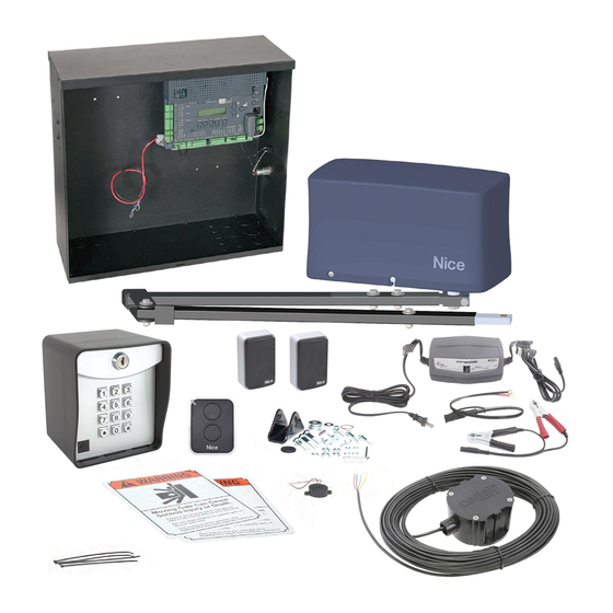
The Apollo 3500 ETL (single gate) and 3600 ETL (dual gate) systems uses a 12 volt - direct
current motor connected to an articulating arm mechanism for opening gates up to 20 feet and
800 pounds per gate. Keep in mind that 3500/3600 operators do NOT utilize the "SMART
ACTUATOR" feature of the 835/836 board - so Program switch #10 must ALWAYS be in the OFF
position.
Trouble Shooting the Apollo 3500/3600ETL systems:
1. Check your battery! The battery in your gate operator is the power source for the entire
system. If it is not adequately charged, the system will not operator properly. Test the
battery by checking the voltage with a volt-meter while the battery is under load (gate
operating). For AC charged systems – unplug the battery charger before load testing
battery. Battery voltage should be 11.5 volt DC or higher while the operator is running
(battery under load).
2. Program Switch Settings: At the upper center of the board there are 10 program
switches. These switches enable and disable certain features of the Apollo system.
DEFAULT setting of these switches is as follows: SINGLE GATE – 1,2,3,5 ON (all others
OFF) DUAL GATE – 1,2,5 ON (all others OFF)
3. LED ENABLE BUTTON: On the right side of the board – half way down is the LED
ENABLE button. Pressing this button once and releasing it "enables" the LEDs on the
board for approximately 15 minutes. When the LEDs are enabled – the "STOP" light
should always be lit on the left side of the board. Other LEDs may be lit as well –
depending on the status of the operator. If the gate(s) are in the OPEN position, the
OPEN limit indicator(s) should be lit. If the gate(s) are CLOSED, the CLOSED limit
indicator(s) should be lit. (The OPEN and CLOSED LEDs should never be on at the
same time) Any LEDs that are lit on the left side of the board or at the lower right corner
of the board (except the STOP LED) indicate a TRIGGER from an accessory device
connected at that location. Devices connected where an LED is lit should be removed
before further testing is done. After the system is made operational – these devices may
be reconnected one at a time. Check for proper system operation after each connection.
4. Current Sensitivity: At the top center of the board is the "Current Sensitivity" adjustment.
It adjusts the amount of force the operator will exert before it senses an obstruction. As
the wheel is turned counter clockwise, the operator will reverse more easily. As the
wheel is turned clockwise, the operator will push harder. Any time the system
"CURRENT SENSES" it will stop and reverse for two (2) seconds. If the system
"CURRENT SENSES" a second time before fully opening or closing – it will again reverse
for two (2)_seconds and then go into a HARD SHUTDOWN (see below). Sensitivity
should be set to a level that is sufficiently strong to open and close the gate in all
conditions – yet still sensitive enough to be safe. A good starting point is the one o'clock
position.
APOLLO 3500/3600 Troubleshooting
Advertisement

Summary of Contents for Apollo 3500 ETL
- Page 1 PROGRAM SWITCH #3 to the OFF position and only using the MASTER receptacle of the board. The Apollo 3500 ETL (single gate) and 3600 ETL (dual gate) systems uses a 12 volt - direct current motor connected to an articulating arm mechanism for opening gates up to 20 feet and 800 pounds per gate.
- Page 2 5. Activating the system: A momentary connection between activation inputs and ground (GND) is how the system is activated. At the upper left and bottom right of the board are terminals marked INP or INPUT. These terminals - when momentarily shorted to ground (GND) - will open, stop and close the gate with each activation.


