Table of Contents
Advertisement
Quick Links
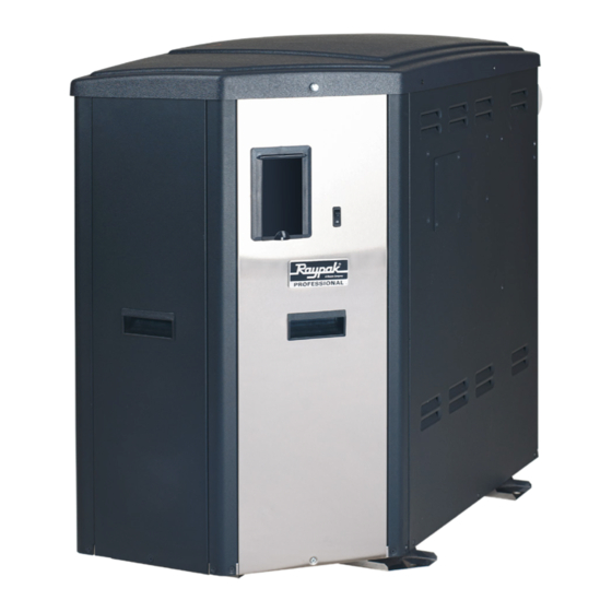
INSTALLATION AND
OPERATION MANUAL
X94 Professional
Gas-Fired
Pool & Spa
Heater
Low NOx Model SR-410
WARNING: If the information in these
A
instructions are not followed exactly, a fire or
explosion may result causing property damage,
personal injury or death
Do not store or use gasoline or other flammable
vapors and liquids or other combustible materials in
the vicinity of this or any other appliance. To do so
may result in an explosion or fire.
WHAT TO DO IF YOU SMELL GAS:
•
Do not try to light any appliance.
•
Do not touch any electrical switch; do not use
any phone in your building.
•
Immediately call your gas supplier from a
neighbor's phone. Follow the gas supplier's
instructions.
•
If you cannot reach your gas supplier, call the fire
department.
Installation and service must be performed by a
qualified installer, service agency or the gas supplier.
This manual should be maintained in legible condition and kept adjacent to the heater or in a safe place for future
reference.
APPROVED
.
UNCONTROLLED DOCUMENT IF PRINTED
AVERTISSEMENT: Assurez-vous de bien
A
suivre les instructions données dans cette notice
pour réduire au minimum le risqué d'incendie
ou d'explosion ou pour éviter tout dommage
matériel, toute blessure ou la mort.
Ne pas entreposer ni utilizer d'essence ou ni d'autres
vapeurs ou liquids inflammables à proimité de cet
appareil ou de tout autre appareil.
CE FAIRE SI VOUS SENTEZ UNE ODEUR DE
GAS:
•
Ne pas tenter d'allumer d'appareil.
•
Ne touchez á aucun interrupteur; ne pas vous
server des téléphones se trouvant dans la
bâtiment.
•
Appelez immédiatement votre fournisseur de
gaz depuis un voisin. Suivre les instructions du
fournisseur.
•
Si vous ne pouvez rejoinder le fournisseur,
appelez le service es incendies.
L'installation et l'entretien doivent être assurés par
un installeur qualifié ou par le fournisseur de gaz.
Effective: 02-05-21
Replaces: 02-15-16
P/N: 241494 Rev. 3
Advertisement
Table of Contents

Related Manuals for Rheem Raypak X94 SR-410


Summary of Contents for Rheem Raypak X94 SR-410
- Page 1 APPROVED INSTALLATION AND OPERATION MANUAL X94 Professional Gas-Fired Pool & Spa Heater Low NOx Model SR-410 AVERTISSEMENT: Assurez-vous de bien WARNING: If the information in these suivre les instructions données dans cette notice instructions are not followed exactly, a fire or pour réduire au minimum le risqué...
- Page 2 APPROVED Revision 3 reflects the following changes: Manual has been brought up to the latest configuration based on its design. Manual reformatted and reorganized plus additional metric information added to text, tables, and figures. Table D added on page 9. Figure 10 added on page 17. Figure 25 and 27 corrected on page 26.
-
Page 3: Table Of Contents
APPROVED CONTENTS 1. WARNINGS ............4 5. WIRING DIAGRAM ..........26 Pay Attention to these Terms ........4 6. CONTROLS ............27 General Safety ............5 General Control Locations ........27 2. WATER CHEMISTRY ..........5 Control Adjustments ..........28 Automatic Chlorinators And Chemical Feeders .. -
Page 4: Warnings
APPROVED 1. WARNINGS Pay Attention to these Terms Indicates the presence of immediate hazards which will cause severe personal injury, death or substantial DANGER property damage if ignored. ndicates the presence of hazards or unsafe practices which could cause severe personal injury, death or WARNING substantial property damage if ignored. -
Page 5: General Safety
APPROVED severely damage the heater. Heat exchanger damage General Safety resulting from chemical imbalance is not covered by the warranty. Elevated water temperature can be hazardous. The U.S. Consumer Product Safety Commission has these For your health and the protection of your pool equipment, guidelines: it is essential that your water be chemically balanced. -
Page 6: Before Installation
APPROVED 3. BEFORE INSTALLATION Receiving Equipment MODEL & SERIAL NO. LOCATED ON The manufacturer recommends that this manual be RATING PLATE reviewed thoroughly before installing your pool/spa heater. If there are any questions that this manual does not answer, please contact the factory or your local representative. -
Page 7: Specifications And Dimensions
APPROVED gas and air density. No hardware changes are required to Specifications And Dimensions adjust the unit for operation from 0-8000 ft. elevation (0- 2438 m). Electrical Requirements: Adjust as required to maintain proper combustion and 120V/1ph/60Hz/5A emissions. POWER CONNECTION (102) (19) 21.3... -
Page 8: Installation
APPROVED INSTALLATION Clearances CALIFORNIA PROPOSITION WARNING: All Heaters This product contains chemicals known to the State of California to cause cancer, birth defects or other For indoor and outdoor clearances from combustible reproductive harm. surfaces see the chart below. Location Indoor Installation WARNING: This unit contains refractory ceramic fiber (RCF) insulation in the combustion chamber. -
Page 9: Indoor Heater Installation
APPROVED For installations in Canada, pool heaters shall not be Back 6 (152) installed with the top of the vent assembly within 10' (3 m) b. 1/2" (13 mm)insulation Right 6 (152) Left 6 (152) below, or to either side, of any opening into the building. board over 1"... - Page 10 APPROVED V = VENT X = AIR INLET F10692 Figure 5. Minimum Clearances from Vent/Air Inlet Terminations – Indoor and Outdoor Installations U.S. Installations Canadian Installations Clearance above grade, veranda, porch, deck, or 1' (30 cm) 1' (30 cm) balcony 4' (1.2 m) below or to side of Clearance to window or door that may be opened opening, minimum 1 ft.
-
Page 11: Combustion And Ventilation Air
APPROVED directly with the outdoors or through vertical Combustion And Ventilation Air duct(s). The total cross-sectional area shall be at least 1 in² of free area per 10,000 BTUH (222 (Indoor Units Only) mm² per kW) of total input rating of all equipment in the room when the opening is communicating The heater must have both combustion and ventilation air. -
Page 12: Support Of Vent Stack
APPROVED Exhaust Heater Venting Certified Vent Materials Combustion Air Combustion Air Supply Configuration Category (Must be UL 1738 or ULC S636) Inlet Materials Vertical Venting Horizontal From Inside Building Through-the-Wall Metallic Vent Venting (such as AL29-4C), Duravent Vertical Venting with PolyPro, ASTM D1785 Sch 40 Galvanized Steel Ducted Combustion... -
Page 13: Venting Installation Tips
APPROVED 8. Terminate vent at least 1 ft (0.3 m) above grade, Treatment Kit (sales order option Z-12). The treatment kit including normal snow line. is connected to the drain system and contains limestone (calcium carbonate) chips to raise the pH level of the 9. - Page 14 APPROVED as the vent outlet. The horizontal breaching of a vent must Termination have an upward slope of not less than 1/4" (6.35 mm) per linear foot (305 mm) from the heater to the vent terminal. The vent terminal should be vertical and should terminate The horizontal portions of the vent shall also be supported outside the building at least 3' (0.91 m) above the highest for the design and weight of the material employed to...
-
Page 15: Horizontal Through-The-Wall Venting (Category Iv)
APPROVED The vent cap is not considered in the overall length of the Horizontal Through-the-Wall venting system. Venting (Category IV) The vent must be installed to prevent flue gas leakage. Care must be taken during assembly to ensure that all joints are Installation sealed properly and are airtight. -
Page 16: Direct Vent - Horizontal Through-The-Wall
APPROVED ALTERNATIVE COMBUSTION Termination AIR INTAKE LOCATION The direct vent cap (sales order option D-11) MUST be D-15 FLUE mounted on the exterior of the building. The direct vent cap TERMINATION cannot be installed in a well or below grade. The direct vent cap must be installed at least 1' (30.5 cm) above ground level and above normal snow levels. -
Page 17: Direct Vent - Vertical
APPROVED instructions for vent materials. Vent material must be listed by a nationally-recognized test agency. 1" (25 mm) The connection from the appliance flue to the stack must MIN. (TYP) be as direct as possible and should be the same size or VENT CAPS STACKED VERTICALLY larger than the vent outlet. -
Page 18: Outdoor Installation
APPROVED Products (800-423-4270). Pipe joints must be positively TEST PORT 3 O-RING sealed. Follow the vent manufacturer’s installation GASKETS instructions carefully. Outdoor Installation A 5" (127 mm) length of 4" schedule 40 PVC pipe and a 4" schedule 40 PVC Tee are provided for typical outdoor installations. -
Page 19: Florida Building Code
APPROVED Florida Building Code FLORIDA BUILDING CODE 2010 ULTIMATE WIND SPEED = 170 MPH (274 km/h), 3 SECOND GUST NOMINAL WIND SPEED = 132 MPH (212 km/h) EXPOSURE = C Gas Heater Model No. 410 20.2" (51.3 cm) 34.1" (86.6 cm) 35.5"... -
Page 20: Gas Supply Connections
APPROVED Gas Supply Connections Gas Pressure Adjustment Locations Gas piping must have a sediment trap ahead of the heater ADJUSTING SCREW = MORE GAS gas controls, and a manual shutoff valve located outside – = LESS GAS the heater jacket. All gas piping should be tested after installation in accordance with local codes. -
Page 21: Flow Rates
APPROVED Flow Rates FROM HEATER PIPE SIZE* MIN. GPM (lpm) MAX. GPM** (lpm) 1-1/4", 1-1/2", 2" 40 (151) 125 (473) * Must maintain minimum flow rate. Pipe size may further restrict flow. ** When flow rates thru the heater exceed maximum allowable GPM, an external auxiliary bypass valve is required. -
Page 22: Electrical Wiring
APPROVED Electrical Wiring BLACK BLACK BLACK NOTE: If it is necessary to replace any of the original wiring, use 105°C wire or its equivalent, and/or 150°C RED/WHITE wire or its equivalent, like the original wiring. SUPPLY RETURN SIDE WHITE WHITE NEUTRAL WARNING: Heaters are factory-wired for a 120 VAC, HEATER... -
Page 23: Plumbing-Water Connections
APPROVED Plumbing—Water Connections The heater has standard right-hand plumbing connections, but can be converted to alternate configurations as shown below. STANDARD RIGHT-HAND CONNECTIONS LEFT-HAND CONNECTIONS LEFT-IN / RIGHT-OUT CONNECTIONS RIGHT-IN / LEFT-OUT CONNECTIONS F10334 Figure 22. Water Connection Configurations Loose Plumbing Parts Setup NOTE: Use appropriate CPVC or CPVC to PVC transition primer and glue for attachments. -
Page 24: Recommended Plumbing Setups
APPROVED Heater must be located so that any water leaks will not Recommended Plumbing Setups damage the structure of adjacent area. PVC pipe may be The heater requires water flow and positive pressure to glued directly into the bypass connections. fire and operate properly. - Page 25 APPROVED MAXIMUM DISTANCE 4 SYSTEM PIPE DIAMETERS, NOT TO EXCEED 12" (305 mm) BYPASS VALVE SYSTEM FLOW MUST EXCEED 120% OF COMBINED HEATER FLOW. F10337 Figure 25. Multiple Pool or Spa Heaters Installation Figure 26. Single Pool/Spa Heater Installation MAXIMUM DISTANCE 4 SYSTEM PIPE DIAMETERS, NOT...
-
Page 26: Wiring Diagram
APPROVED 5. WIRING DIAGRAM UNCONTROLLED DOCUMENT IF PRINTED... -
Page 27: Controls
APPROVED 6. CONTROLS NOTE: do not stand on the top of the unit, or put weight on it. General Control Locations VENT PRESSURE SWITCH COMBUSTION AIR ACCESS PANEL F10341 Figure 28. Location of Controls UNCONTROLLED DOCUMENT IF PRINTED... -
Page 28: Control Adjustments
APPROVED Control Adjustments Thermostat Operation - Ignition Control Board PROGRAM BUTTON (SW1) Figure 31. Ignition Control Board F10342 Controls Operation Figure 29. Control Adjustments The pool heater touchpad, located on the upper portion of the angled corner panel of the heater, allows the user to select the mode of operation, adjust the setpoint Control Panel Removal temperature, configure the heater controls and access... -
Page 29: Installer Setup Mode
APPROVED select filter pump speed, activate or deactivate heating, without removing the wiring). In Installer Setup Mode the select valve positions (if used) and turn auxiliary relays on UP and DOWN buttons are used to modify items and the (if used) for the desired override time period. MODE button is used to move between menu items and to store changes. - Page 30 APPROVED required heating load. Comfort mode provides a steady Spa Heat Speed (Selection available only with Pump stream of heated water to the spa, reducing heater on/off Operation enabled and 2, 4 or Variable speed pump) cycles. Use the UP and DOWN buttons to select between the Flue Monitor –...
-
Page 31: Status And Diagnostics
APPROVED pool heaters on an EcoNet network. Valve Change Delay (Selection available only with Valve Operation enabled) Set Factory Defaults Use the UP and DOWN buttons to enable or disable the Use the UP and Down buttons to select Yes or No. Valve Change Delay function. - Page 32 APPROVED Display Condition WPS Stuck Closed Valves not operated because the water flow switch is closed and Valve Chng Delay is enabled Water Sw Open Heat not running because the water flow switch is open Valve Chng Delay Pump/Heat shut off because of valve switching High Heating Second stage heat is running with EXT HEAT Aux mode Heating...
-
Page 33: Remote Control Installation And Operation
APPROVED For operation of the heater using the on board thermostatic Remote Control Installation controls with a time clock, see "Time Clock/Fireman’s And Operation Switch" on page 35. CAUTION: Before installing remote controls to the Activating The Remote heaters, read the following: The digital thermostat model is remote-ready in most To activate or deactivate the remote function, follow these cases. -
Page 34: Remote Control Wiring
APPROVED Remote Control Wiring P8 Connector Important Installation Notes for Remote or External Wiring Configuration • Remote wiring must be run in a separate conduit. • Remote wiring must not be run parallel to high voltage lines. • For runs of under 30 ft (9.1 m), remote wiring should have stranded conductors with a minimum of 22 BLU - 24VAC AWG, 600V, cable twisting 1.5 to 2.5 inch (38 to 64... -
Page 35: Time Clock/Fireman's Switch
APPROVED Time Clock/Fireman’s Switch To operate the heater with a time clock, connect the timer to the fireman’s switch connection in the heater’s wiring. The time clock should be of the dual switch type and set to shut off the call for heat to the pool heater 15 to 20 minutes prior to shutting down the pool pump. -
Page 36: Visual Inspection
APPROVED ADJUSTING SCREW Combustion Settings = MORE GAS – = LESS GAS Verify that the gas orifice matches the fuel type supplied. The natural brass finish orifice is for natural gas and the black oxide finish orifice is for Propane. Table K shows the desired ranges for CO2 % and limits for CO ppm. -
Page 37: Owner's Operating Instructions
APPROVED 7. Double check incoming electrical power, verify 7. OWNER’S OPERATING sufficient supply of 120V/1ph/60Hz power to the INSTRUCTIONS heater. 8. If installed indoors, make sure flue gases are vented FOR YOUR SAFETY - READ BEFORE OPERATING properly, and that combustion and makeup air openings are adequate and clear of obstruction. -
Page 38: Maintenance And Care
APPROVED 21. Visually check through the sight glass that the heater 8. MAINTENANCE AND CARE is on and heating. An orange glow indicates that the heater is running. At high fire, the flame should be Care Procedures visible. The flame should be blue in color with some orange streaks when the air/fuel ratio is correct. -
Page 39: Lighting And Shutdown
APPROVED Lighting and Shutdown WARNING: Should overheating occur or the gas supply fails to shutoff, turn off the manual gas control CAUTION: Propane gas is heavier than air and will to the heater. settle on the ground. Since propane can accumulate in confined areas, extra care should be exercised when AVERTISSEMENT: En cas de surchauffe ou lighting propane heaters. -
Page 40: Chlorination And Water Chemistry
APPROVED Chlorination and Water Chemistry See section "Water Chemistry" on page 5. Cold Weather Operation Important Freeze Information MODERATE CLIMATE: Heater operation can continue during short-term cold spells. When temperatures are between 0°F (-18°C) and 32°F (0°C), flow (continuous pump operation) must be maintained. CAUTION: Do not use the heater to maintain water temperatures just above freezing or for freeze protection. -
Page 41: Troubleshooting
APPROVED 9. TROUBLESHOOTING IMPORTANT NOTICE These instructions are intended for the use of qualified personnel who are specifically trained and experienced in the installation of this type Mechanical of heating equipment and related system components. Installation and service personnel may be required by some states to be licensed. -
Page 42: Control Logic - Flow Chart (Pool & Spa Modes)
APPROVED Control Logic - Flow Chart (Pool & Spa Modes) UNCONTROLLED DOCUMENT IF PRINTED... -
Page 43: Illustrated Parts List
APPROVED 10. ILLUSTRATED PARTS LIST UNCONTROLLED DOCUMENT IF PRINTED... - Page 44 APPROVED 13-H UNCONTROLLED DOCUMENT IF PRINTED...
- Page 45 APPROVED If determined defective by the Company and within NOTE: To supply you with the correct part, it is warranty, a like part or equal substitution will be returned, important that you supply the heater model number, freight collect. Credit will not be issued. serial number and type of gas when applicable.
- Page 46 APPROVED CALL KIT NO. DESCRIPTION MISCELLANEOUS COMPONENTS 007223F PRV 75 PSI 014647F T & P Gauge 015467F Wire Harnesses (All Unit Harnesses) 015468F Cabinet Harness 015469F Blower Harness 120V 015470F Gas Valve Harness 015471F High Limit / Flow Switch Harness 015472F Condensate Float Switch Harness 015555F...
-
Page 47: Important Instructions For The Commonwealth Of Massachusetts
APPROVED 11. IMPORTANT INSTRUCTIONS FOR THE COMMONWEALTH OF MASSACHUSETTS Commonwealth Massachusetts requires 4. INSPECTION. The state or local gas inspector of the compliance with regulation 248 CMR 4.00 and 5.00 for sidewall horizontally-vented gas-fueled equipment shall installation of through – the – wall vented gas appliances not approve the installation unless, upon inspection, as follows: the inspector observes carbon monoxide detectors and... -
Page 48: Installer Setup Record
APPROVED 12. INSTALLER SETUP RECORD Use this sheet to record Installer Setup Mode settings. This record will simplify setup in the event it is necessary to Reset Factory Defaults or install a new control. It is also a helpful troubleshooting tool, allowing all setup parameters to be viewed on a single page. -
Page 49: Warranty
APPROVED 13. WARRANTY LIMITED WARRANTY SERIES GAS POOL AND SPA HEATERS X94 Professional Model: 410 SCOPE OF WARRANTY Raypak, Inc. (Raypak) warrants to the original owner that the above model gas pool and spa heater (the “Heater”) when installed in the contiguous 48 states of the United States of America with a pool or spa by a properly licensed installer will be free from defects in materials and workmanship under normal use and service for the Applicable Warranty Period. - Page 50 BUSINESS RECORDS. Register your product online at www.raypak.com/warranty RAYPAK, INC., 2151 Eastman Avenue, Oxnard, CA 93030 • (805) 278-5300 FAX (800) 872-9725 Rheem Canada Ltd/Ltée. 125 Edgeware Road, Unit 1,Brampton, Ontario L6Y 0P5 CANADA P/N 241581 UNCONTROLLED DOCUMENT IF PRINTED...
- Page 51 APPROVED NOTES UNCONTROLLED DOCUMENT IF PRINTED...
- Page 52 APPROVED ISO 9001 REGISTERED QUALITY MANAGEMENT SYSTEM Raypak, Inc. 2151 Eastman Avenue, Oxnard, CA 93030 (805) 278-5300 www.raypak.com www.raypak.com UNCONTROLLED DOCUMENT IF PRINTED...