Monogram ZGP366N Important Service Information
Hide thumbs
Also See for ZGP366N:
- Technical service manual (86 pages) ,
- Owner's manual (128 pages) ,
- Installation instructions manual (80 pages)
Advertisement
Available languages
Available languages
Quick Links
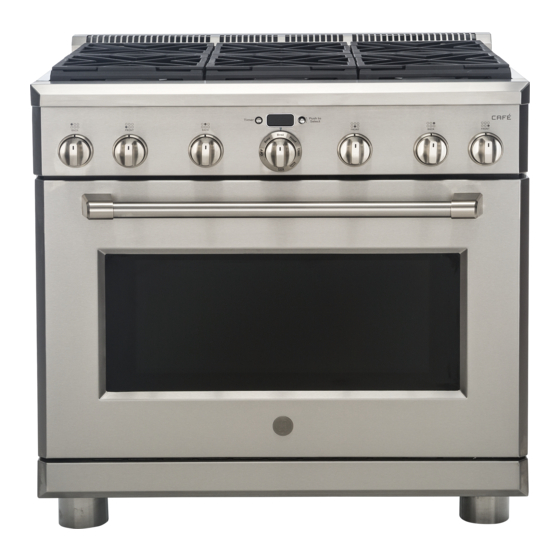
36" ALL GAS RANGES
36" Natural Gas Surface Burner Models: ZGP366N,
ZGP364NR, ZGP364ND, CGY366SELSS
36" Propane (LP) Gas Surface Burner Models:
ZGP366L, ZGP364LR, ZGP364LDS
WARNING
Explosion Hazard
Death or serious injury can result from failure to follow
these instructions.
• Service by a qualified service technician only.
• Shut off gas supply and disconnect power before
servicing.
• Reconnect all grounding devices after service.
• Replace all parts and panels before operating.
GAS SUPPLY REQUIREMENTS
INCOMING PRESSURE
PRESSURE REGULATOR
GAS TYPE
TO REGULATOR
OUTPUT
Natural
Propane (LP)
The cooktop, as shipped from the
WARNING
factory, is set for use with its intended
gas. If you wish to use your cooktop with the alternate
gas, you must first replace the orifices and convert
the pressure regulator. Failure to do so may result in
carbon monoxide poisoning or fire.
GAS CONVERSION KIT
The gas conversion kit is located behind the front access panel at
the bottom of the range. Please refer to the Installation Instructions
for details on removal.
HIGH ALTITUDE KIT
Conversion Kit. This kit includes orifices for both propane (LP) and
natural gas operation.
ANTI-TIP DEVICE
The Anti-Tip Bracket must be properly installed to prevent tipping
of the range. Failure to do so can cause serious damage or injury.
After servicing, roll the range into position, being careful not to
entangle or pinch the power cord and flexible gas tubing. Make
sure the Anti-Tip Bracket is engaged.
Be sure Anti-Tip Bracket
is engaged with the
brace on the range.
REMOVE/REPLACE RANGE
To roll the range from its location for service, lower the range onto its
wheels by retracting its four leveling legs.
FRONT LEVELING LEGS ADJUSTMENT
A leveling leg wrench is supplied. Reach under the front of the range
near the right side. Locate and remove a thumb screw, then slide the
wrench out of the slot.
Slide the front cylinders up to adjust the front leveling legs. Be careful
not to damage the cylinder.
Thumb Screw
Use the supplied wrench to turn the
front leveling legs. Turn clockwise to
raise the range above the wheels.
Turn counterclockwise to lower the
legs.
Be sure to return the wrench to its
storage slot for future use.
REAR LEVELING LEGS ADJUSTMENT
Remove the two screws from the rear vent trim. Slide the vent trim
forward, then lift up to remove.
Find the two rear leg extension rods. Use a 1/4" driver or wrench on
the extension rods to adjust the rear legs.
Rear Vent Trim
Rear Leg
Extension Rod
CONTROL PANEL REMOVAL
Pull the surface knobs off and remove the screws from each bezel.
Remove the screws from the control panel face. NOTE: Do not
remove the oven control knob.
Remove the screws from the bottom of the control panel and from the
top (inside flanges, on each side, on the back side of the panel).
Control Panel
Bezels
Surface Knobs
ACCENT LIGHTING REPLACEMENT
Remove the control panel. See the CONTROL PANEL REMOVAL
section.
Loosen the accent lighting module's screw, slide out and replace.
Loosen
Set Screw
SURFACE KNOB INDICATOR LIGHT REPLACEMENT
Remove the control panel. See the CONTROL PANEL REMOVAL
section. Find the indicator light on top of the gas valve, remove the
attached screw and replace.
GAS MANIFOLD AND VALVE REPLACEMENT
Refer to the Service Manual for replacement procedure.
OVEN CONTROL ACCESS
Remove the control panel. See the CONTROL PANEL REMOVAL
section.
The oven control is mounted to the back side of the control panel.
Slide leg
SPARK MODULE REPLACEMENT
cylinder
1. Roll the range from its installation position.
up.
See the REMOVE/REPLACE RANGE section.
2. Remove the control panel. See the CONTROL PANEL
REMOVAL section.
3. Remove the two screws from the rear vent trim and remove the
trim.
4. Remove the side range panel by removing the screws on the
back of the range and the screws from the range face top inner
corners, and then lift the panel up and off of its front keyhole
mounting slots.
5. Remove the left grates and left grate frame. Remove surface
burners by removing all screws, but keep the outside burner
screws separate from the inside burner screws so they can
be easily replaced. Remove the burner pan, burner insulation
and spark module cover. Disconnect the igniter wires by pulling
them off of the connector pins.
Spark Module Cover
GRILL IGNITER REPLACEMENT
Remove the grill cover, grate,
grate frame and radiant baffle.
Remove the screws from each
side of the pan surround and
remove the pan surround.
Remove the screws from the
igniter and pull the igniter
connector from the opening.
Disconnect the connector pin
and replace the igniter. Push
the igniter connector back into
the opening and replace all
parts.
GRIDDLE IGNITER REPLACEMENT
Lift off the griddle flue cover. Remove the 2 inside clamping screws.
NOTE: Remove the 2 screws positioned on the inside only. Do not
remove the outermost screws—they are for leveling the griddle.
Slide the griddle toward the rear and out of the hold-down tabs
along the bottom front.
CAREFULLY lift and hold the griddle. A thermostat capillary is
routed through a clip. Gently lift the griddle to one side and slip the
capillary out of the clip. Do not disconnect or pull on the capillary.
Gently lay the griddle aside.
Remove the 2 burner hold-down screws at the rear of the burner
to loosen the burner. Remove the screws attaching the igniter.
Pull the igniter connector from the opening, disconnect the pin
connection and replace the igniter. Route the capillary back into
the clip. Push the excess capillary back through the opening. Push
the igniter connector back into the opening and replace all parts.
Grates
Igniter
Grate Frame
Slide back
griddle and
lift front
Avoid routing capillary
Surface
through burner flame area.
Burners
Burner Pan
Burner
Insulation
Grill
Grate
Grill
Grate
Frame
Radiant
Baffle
Pan
Surround
Capillary
Griddle Flue Cover
Leveling
Screws
Clamping
Screws
Advertisement

Related Manuals for Monogram ZGP366N


Summary of Contents for Monogram ZGP366N
- Page 1 To roll the range from its location for service, lower the range onto its Remove the control panel. See the CONTROL PANEL REMOVAL Remove the grill cover, grate, 36” Natural Gas Surface Burner Models: ZGP366N, Grill section. Find the indicator light on top of the gas valve, remove the grate frame and radiant baffle.
- Page 2 LOCKED DOOR REMOVAL ERC FAILURE CODES OVEN BURNER IGNITION SYSTEM REED SWITCH If the door is locked and cannot be The ignitor is a “Norton” style rectangular glow bar. The ignition circuit The last 7 Failure (F) codes are stored in the nonvolatile memory, The reed switch is located at the top rear of the range, behind the unlocked, it may be removed for accessed through the factory test mode.
- Page 5 Enlevez le panneau de contrôle. Voir la section ENLÈVEMENT DU PANNEAU au gaz naturel : ZGP366N, ZGP364NR, ZGP364ND, DE CONTRÔLE. Repérez le témoin lumineux sur le dessus de la soupape du radiant.
- Page 6 REMPLACEMENT DU VEROUILLAGE DE PORTE CODES D’ÉCHEC D’ERC SYSTÈME D’ALLUMAGE DES BRÛLEURS DU FOUR COMMUTATEUR À LAMES Les 7 derniers codes d’échecs (F) sont enregistrés dans la mémoire non Si la porte est fermée et impossible à L’allumeur est un « Norton » du type rectangulaire à incandescence. Le circuit Le commutateur à...