Table of Contents
Advertisement
Advertisement
Table of Contents

Related Manuals for Extreme Networks ExtremeSwitching Virtual Services Platform 8000 Series


Summary of Contents for Extreme Networks ExtremeSwitching Virtual Services Platform 8000 Series
- Page 1 Installing the Virtual Services Platform 8000 Series 9035365 Rev 02 March 2020...
- Page 2 2017-2020, Extreme Networks, Inc. All Rights Reserved. Legal Notice Extreme Networks, Inc. reserves the right to make changes in specifications and other information contained in this document and its website without prior notice. The reader should in all cases consult representatives of Extreme Networks to determine whether any such changes have been made.
-
Page 3: Table Of Contents
Contents Chapter 1: About this Document..................... 5 .......................... 5 Purpose .......................... 5 Conventions ....................... 5 Text Conventions ..................... 7 Documentation and Training .......................... 7 Getting Help ......................... 8 Providing Feedback Chapter 2: New in this document.................. 10 Chapter 3: Hardware models for VSP 8000 Series............... 11 .................. 16 Power cord types and order codes Chapter 4: Preinstallation checklist.................. - Page 4 Contents ........................ 80 Airflow direction ...................... 80 Install a Fan Module ...................... 82 LED state definitions ........................ 82 Switch LEDs ................ 83 Management port LED state indicators .......... 84 SFP, SFP+,QSFP+, and QSFP28 port LED state indicators .................. 85 RJ45 port LED state indicators ..................
-
Page 5: Chapter 1: About This Document
Extreme Networks publications. Purpose This guide provides information and instructions to install the Extreme Networks Virtual Services Platform 8000 Series (VSP 8000 Series) switches. The VSP 8000 Series includes the VSP 8200 Series and the VSP 8400 Series. - Page 6 About this Document Table 2: Text Conventions Convention Description Angle brackets ( < > ) Angle brackets ( < > ) indicate that you choose the text to enter based on the description inside the brackets. Do not type the brackets when you enter the command.
-
Page 7: Documentation And Training
Data Center products Other resources, like white papers, data sheets, and case studies Extreme Networks offers product training courses, both online and in person, as well as specialized certifications. For details, visit www.extremenetworks.com/education/. Getting Help If you require assistance, contact Extreme Networks using one of the following methods: Extreme Search the GTAC (Global Technical Assistance Center) knowledge base;... -
Page 8: Providing Feedback
579 2826. For the support phone number in your country, visit: www.extremenetworks.com/support/contact Before contacting Extreme Networks for technical support, have the following information ready: • Your Extreme Networks service contract number, or serial numbers for all involved Extreme Networks products • A description of the failure •... - Page 9 Providing Feedback • Broken links or usability issues. If you would like to provide feedback, you can do so in three ways: • In a web browser, select the feedback icon and complete the online feedback form. • Access the feedback form at https://www.extremenetworks.com/documentation-feedback/. •...
-
Page 10: Chapter 2: New In This Document
Chapter 2: New in this document The following section details what is new in this document. Temperature Sensors Warning and critical threshold values are updated in the document. For more information, see Install a Fan Module on page 80. March 2020 Installing the VSP 8000 Series... -
Page 11: Chapter 3: Hardware Models For Vsp 8000 Series
Chapter 3: Hardware models for VSP 8000 Series This section lists the VSP 8000 Series hardware. VSP 8200 Series Hardware Power cords must be ordered separately. Ensure you order the correct power cord for your region. For more information, see Power cord types and order codes on page 16. - Page 12 Hardware models for VSP 8000 Series VSP 8284XSQ Description Part number 800 watt AC redundant power • The VSP 8284XSQ comes with one 800 W AC EC8005A01-E6 supply PSU. • For full power redundancy, you can install a second 800 W AC PSU. 800 watt DC redundant power •...
- Page 13 VSP 8404 Description Part number replaceable 800 watt AC power supply but no power cord. VSP 8404C AC Includes all of the above components. EC8400A02-E6 This model number ships with one field-replaceable 800 watt AC power supply. VSP 8404C-AC No PC GSA Includes all of the above components.
- Page 14 Hardware models for VSP 8000 Series VSP 8404 Description Part number Note: The universal slide rack mount kit is optional and must be ordered separately. The VSP 7200 Series, VSP 8200 Series and VSP 8400 Series ship with rack mount brackets. When using rack mount brackets on the VSP 8200 Series and VSP 8400 Series, we recommend the use of a shelf to provide additional support.
- Page 15 Important: We recommend using the SFP, SFP+, QSFP+, and QSFP28 transceivers as they have been through extensive qualification and testing. Extreme Networks will not be responsible for issues related to third party transceivers. • The VSP 8000 Series operates in forgiving mode for SFP, SFP+, and QSFP+ transceivers, which means that the switch will bring up the port operationally when using third party transceivers (SFP, SFP+ or QSFP+).
-
Page 16: Power Cord Types And Order Codes
Hardware models for VSP 8000 Series Power cord types and order codes To connect AC power to the switch, you need an appropriate AC power cord as described in the following table. Table 6: Power cords for power distribution units Order Code Length Power supply side... -
Page 17: Chapter 4: Preinstallation Checklist
Package contents on page 34 for a package. description of the components that are provided with the switch. If any components are missing, contact Extreme Networks support. Make sure that the power cord has the correct country-specific termination. Prepare the rack. - Page 18 Preinstallation checklist Task Description permanent and must not exceed 1 Ohm of resistance from the rack to the grounding electrode. March 2020 Installing the VSP 8000 Series...
-
Page 19: Chapter 5: Installing The Virtual Services Platform 8000 Series
Chapter 5: Installing the Virtual Services Platform 8000 Series This section provides the information and procedures to install the VSP 8000 Series. Installation checklist Use this checklist to install the VSP 8000 Series. Task Description Mount the VSP 8000 Series switch in Installing the VSP 8000 Series in an the equipment rack. -
Page 20: Installation Fundamentals
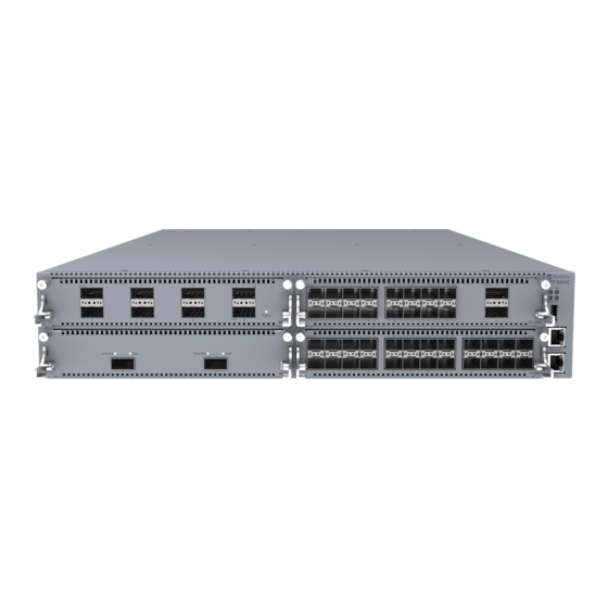
Installing the Virtual Services Platform 8000 Series Installation fundamentals VSP 8200 Series The VSP 8200 Series consists of: • eighty 10GBASE-SFP/SFP+ ports • four 40GBASE-QSFP+ ports • one 10/100/1000BASE-T Out-Of-Band Management Port • one RJ-45 Console Port • one USB 2.0 port •... - Page 21 Installation fundamentals 7. Management port — The LEDs are on the bottom of the port. For more information, see Management port LEDs on page 83. 8. LEDs for system power (PWR), switch status (Status), redundant power supply (RPS), and fan modules (Fan).
-
Page 22: Ethernet Switch Module
Installing the Virtual Services Platform 8000 Series Note: • The front view is common for both VSP 8404 and VSP 8404C models. • When looking at the front of the switch, slot numbering begins at the top row and increases from left to right. - Page 23 Ethernet Switch Module Weight 3.80 lbs = 1.72 kg Power and 93.32W (max) = 318.41 BTU/hr thermal Figure 4: 8424XS 8424XT • 8424XT — EC8404002-E6 – provides 24 100MB/1G/10G Copper ports. • 8424XT (GSA version) — EC8404002-E6GS – 24 port 100MB/1G/10G Copper ports. Dimension 4.4cm –...
- Page 24 Installing the Virtual Services Platform 8000 Series Important: As shown in the above figure, ports 7 and 8 are reserved for future use. 8418XSQ • 8418XSQ — EC8404005-E6 – 16 1/10G SFP+ and 2 40G QSFP+ ports. • 8418XSQ (GSA version) — EC8404005-E6GS – 16 1/10G SFP+ and 2 40G QSFP+ ports. Dimension 4.4cm –...
- Page 25 Ethernet Switch Module Figure 9: 8424GS 8424GT • 8424GT — EC8404008-E6 – 24 10/100/1000M Copper ports. • 8424GT (GSA version) — EC8404008-E6GS – 24-port 10/100/1000M Copper ports. Dimension 4.4cm – 1RU (H), 20.32cm (W), 29.21cm (D) Weight 2.75 lbs = 1.25 kg Power and 12.62W (max) = 47.90 BTU/hr thermal...
-
Page 26: Installing An Ethernet Switch Module
Installing the Virtual Services Platform 8000 Series Installing an Ethernet Switch Module Install an ESM to replace an existing module or to add new capability. The switch has four bays and you can choose any one of them to install a module. The switch detects where the modules are installed so the order is not important. - Page 27 Ethernet Switch Module 2. Slide the module into the bay. 3. Apply gentle pressure anywhere on the faceplate to fully insert the module, and then screw the module in to ensure a good connection and to secure it to the chassis. March 2020 Installing the VSP 8000 Series...
-
Page 28: Hot Swap Of Vsp 8400 Series Ethernet Switch Module
Installing the Virtual Services Platform 8000 Series Note: The levers are designed to stay in the position shown when the module is inserted into the chassis. The levers are pulled upwards to extract the module. If you have to remove a module, loosen the two screws that secure the module to the chassis and rotate the extract levers up to eject the module from the chassis. - Page 29 Ethernet Switch Module Table 8: Methods of hot swapping in VSP 8400 Series Hardware Description Power supply You can hot swap power supplies while the switch is operational. One power supply is required for continuous switch operation. 8402CQ ESM Hot insertion or removal of the 8402CQ is not supported. 8402CQ can only be hot swapped with another 8402CQ using Performing a Important:...
-
Page 30: 40G Channelization
40Gbps QSFP+ ports operate as 40Gbps ports. You can enable or disable channelization on a port. For breakout cable (BOC) details, see Extreme Networks Pluggable Transceivers Installation Guide. March 2020... -
Page 31: Electrostatic Discharge
• Do not remove the wrist or ankle strap until the installation is complete. Preventing electrostatic damage in new cable installations With new cable installations, Extreme Networks recommends that you use an ESD discharge cable to reduce the potential for damage from static, that can build up in cables. The following figure illustrates an ESD cable. -
Page 32: Technical Specifications
Installing the Virtual Services Platform 8000 Series Figure 12: Job aid To install the ESD discharge cable, perform this procedure. 1. Connect the ground lug on the ESD discharge cable to a safe and suitable earth ground. 2. Connect all RJ-45 cable connectors to the female RJ-45 connector of the ESD discharge cable for at least 5 seconds, and then connect each RJ-45 cable connector to the switch. - Page 33 Technical specifications Specifications VSP 8200 Series VSP 8400 Series power supplies or ESMs) (EC8400x01-E6) Weight of spare AC power 1.9 lb (0.862 kg) (EC8005x01-E6) 1.9 lb (0.862 kg) (EC8005x01-E6) supply unit Weight of spare DC power 1.76 lb (0.8 kg) (EC8005001-E6) 1.76 lb (0.8 kg) (EC8005001-E6) supply unit Table 10: Electrical specifications...
-
Page 34: Package Contents
• Cables should be dressed to prevent blocking air flow. Package contents The following describes the components that are provided with each switch. If any components are missing, contact Extreme Networks. 1. VSP 8000 Series switch 2. Rack-mounting hardware that includes: •... -
Page 35: Installing The Vsp 8000 Series In An Equipment Rack
It is highly recommended to mount the chassis on a tray designed for the specific rack and use the Extreme Networks supplied rack mount brackets to hold the chassis in place. The chassis is heavy and could cause damage to a rack if only the brackets are used, especially in a vibration prone area. - Page 36 Installing the Virtual Services Platform 8000 Series This kit is a separately ordered item (Part # EC8011002). For instructions see: • Inventory of slide components on page 36 • Installing slides in a 300mm-600mm equipment rack on page 44 • Installing slides in a 600mm-900mm equipment rack on page 52 •...
- Page 37 Installing the VSP 8000 Series in an Equipment Rack Figure 13: Shipping components Rails The following figure shows a slide rail in the default configuration for a 300mm-600mm equipment rack. This configuration comes with the short rear bracket installed. The slide rail actually consists of two separate rails that slide into each other: •...
- Page 38 Installing the Virtual Services Platform 8000 Series Figure 14: Rails Brackets There are three different brackets: • Short rear bracket—The slide rail kit comes with this bracket installed for the 300mm-600mm default configuration. Figure 15: Short rear bracket March 2020 Installing the VSP 8000 Series...
- Page 39 Installing the VSP 8000 Series in an Equipment Rack • Extension bracket—This bracket connects to the rack rail to lengthen it for a 600mm-900mm configuration. • Long rear bracket—This bracket replaces the short rear bracket to modify the slide rail for a 600mm-900mm configuration.
- Page 40 Installing the Virtual Services Platform 8000 Series Figure 17: Thumbscrew lock and release latches • Thumbscrew lock—This feature is on the front end of the chassis rails, and is used to lock the switch in the home position of the equipment rack. Figure 18: Thumbscrew lock March 2020 Installing the VSP 8000 Series...
- Page 41 Installing the VSP 8000 Series in an Equipment Rack • White release latch—This latch is the white, plastic tab on the chassis rails. - When you first install the slide rails, use these latches to disconnect the chassis rail from the rack rail so you can install the chassis rail on the switch.
- Page 42 Installing the Virtual Services Platform 8000 Series Figure 21: Blue locking mechanism - When you first install the slide rails and you fully extended the rail, you can lift the locking mechanism to release the rail so it can slide back into the main part of the unit. - When you install the switch in a rack and then pull the switch out, this mechanism automatically locks the slide rail in a fully extended position.
- Page 43 Installing the VSP 8000 Series in an Equipment Rack • Pin block—The pin block supports equipment racks with different shaped holes. - For racks with square holes, the pin block fits right into the holes in the rack. - For racks with large round holes, the pin block retracts halfway when you insert the rail into the rack.
- Page 44 Installing the Virtual Services Platform 8000 Series Installing slides in a 300mm-600mm equipment rack Use the following procedure to install your switch in an equipment rack with a depth between 300mm and 600mm. Before you begin Important: The Slide Rack Mount Kit is fairly complex due to its versatile design. To make your installation easier, read the Inventory of slide components on page 36 section to familiarize yourself with...
- Page 45 Installing the VSP 8000 Series in an Equipment Rack b. Pull the inner chassis rail and slide it out as far as you can. March 2020 Installing the VSP 8000 Series...
- Page 46 Installing the Virtual Services Platform 8000 Series c. Slide the white release latch in the direction of the arrow stamped on the lock and pull the chassis rail out of the rack rail. 4. Lift the blue locking mechanism on the rack rail to slide the outer section back into the main section.
- Page 47 Installing the VSP 8000 Series in an Equipment Rack 5. Use the following steps to attach the chassis rail to the chassis: a. Orient the chassis rail with the thumbscrew lock towards the front and position the rail over the standoffs on the chassis. b.
- Page 48 Installing the Virtual Services Platform 8000 Series c. Make sure the safety tab locks into place. 6. Use the following steps to secure the rack rails to the frame: a. Orient the rack rail so that the end with the black retaining latch is facing front. b.
- Page 49 Installing the VSP 8000 Series in an Equipment Rack c. Push the end of the retaining latch out so it opens up. d. Insert the bracket pins into the desired holes in the frame. The pin block accommodates three different rack types. In the default position, the pin block fits into racks with square holes.
- Page 50 Installing the Virtual Services Platform 8000 Series e. Close the retaining latch so that it wraps around the frame and locks into place. f. Repeat the above steps on the rear bracket. g. Repeat these steps for the rack rail on the other side of the frame. 7.
- Page 51 Installing the VSP 8000 Series in an Equipment Rack b. Pull the blue latches on the chassis rails towards the front and slide the switch into the frame. Note: After you install the switch in a rack, slide it out until the lock (shown above) engages. To slide the switch back into the rack, push the blue release latches on the chassis rails towards the back and slide the switch into the frame.
- Page 52 Installing the Virtual Services Platform 8000 Series Installing slides in a 600mm-900mm equipment rack Use the following procedure to install your switch in an equipment rack with a depth between 600mm and 900mm. Before you begin Important: The Slide Rack Mount Kit is fairly complex due to its versatile design. To make your installation easier, read the Inventory of slide components on page 36 section to familiarize yourself with...
- Page 53 Installing the VSP 8000 Series in an Equipment Rack b. Pull the inner chassis rail and slide it out as far as you can. March 2020 Installing the VSP 8000 Series...
- Page 54 Installing the Virtual Services Platform 8000 Series c. Slide the white release latch in the direction of the arrow stamped on the lock and pull the chassis rail out of the rack rail. 4. Lift the blue locking mechanism on the rack rail to slide the outer section back into the main section.
- Page 55 Installing the VSP 8000 Series in an Equipment Rack 5. Use the following steps to attach the chassis rail to the chassis: a. Orient the chassis rail with the thumbscrew lock towards the front and position the rail over the standoffs on the chassis. b.
- Page 56 Installing the Virtual Services Platform 8000 Series c. Make sure the safety tab locks into place. 6. Remove the two screws and nuts securing the short rear bracket to the rack rail. This bracket is for 300mm-600mm equipment racks only and is not used in this installation. Save the bracket for possible future use.
- Page 57 Installing the VSP 8000 Series in an Equipment Rack 7. Identify the extension bracket and the long rear bracket. Use these brackets to extend the rack rail for 600mm-900mm racks. March 2020 Installing the VSP 8000 Series...
- Page 58 Installing the Virtual Services Platform 8000 Series 8. Use the countersink screws with the following steps to attach the extension bracket to the rack rail: a. Push the blue release lock up and slide the middle rail out as far as possible. b.
- Page 59 Installing the VSP 8000 Series in an Equipment Rack Note: Using the bag with ten M4 screws, attach the extension bracket to the rack rail by inserting the screws from the rack rail side and then into the extension bracket. The following figure shows the extension bracket attached to the rack rail.
- Page 60 Installing the Virtual Services Platform 8000 Series d. Insert the long rear bracket into the extension bracket assembly. e. Install the first two screws on the end of the long rear bracket. f. Lift the blue locking mechanism and slowly slide the rail back into the main assembly. This exposes a “window”...
- Page 61 Installing the VSP 8000 Series in an Equipment Rack screws one at a time. 9. Use the following steps to secure the rack rails to the frame: a. Orient the rack rail so that the end with the black retaining latch is in the front of the rack.
- Page 62 Installing the Virtual Services Platform 8000 Series c. Push the end of the retaining latch out so it opens up. d. Insert the bracket pins into the desired holes in the frame. The pin block accommodates three different rack types. In the default position, the pin block fits into racks with square holes.
- Page 63 Installing the VSP 8000 Series in an Equipment Rack e. Close the retaining latch so that it wraps around the frame and locks into place. f. Repeat the above steps on the rear bracket. 10. Repeat these steps for the rack rail on the other side of the frame. 11.
- Page 64 Installing the Virtual Services Platform 8000 Series b. Pull the blue release latches on the chassis rails towards the front and slide the switch into the frame. Note: After you install the switch in a rack, slide it out until the lock (shown above) engages. To slide the switch back into the rack, push the blue locks on the chassis rails towards the back and slide the switch into the frame.
- Page 65 Installing the VSP 8000 Series in an Equipment Rack Important notice about rack safety One prerequisite to installing the switch in an equipment rack is to bolt the equipment rack to the floor. This section emphasizes the safety issue if you do not bolt the rack to the floor. Warning: If you pull the chassis all the way out on the slide rails, there is a danger of the rack tipping over if the rack is not bolted to the floor.
- Page 66 Installing the Virtual Services Platform 8000 Series Removing the switch from an equipment rack Follow these steps if you have to remove the switch from an equipment rack. Important: This procedure requires two people. Procedure 1. Disconnect the power cord from the switch. 2.
- Page 67 Installing the VSP 8000 Series in an Equipment Rack 3. While the person standing in back of the chassis slides both of the white release locks (one on each side of the chassis) towards the front, the person standing in front of the chassis pulls the chassis out of the rack.
-
Page 68: Using The Supplied Brackets
Installing the Virtual Services Platform 8000 Series Using the supplied brackets This procedure describes how to install the switch using the supplied brackets on a two-post or four- post equipment rack. The brackets secure the chassis and prevent it from sliding around during vibration or when inserting or extracting transceivers. -
Page 69: Cable Requirements For The Vsp 8000 Series
Cable requirements for the VSP 8000 Series 4. Insert and tighten the rack-mount screws. 5. Verify that the switch is securely fastened to the rack. 6. Connect power and network connections to the switch. Cable requirements for the VSP 8000 Series The following table describes the cables required for a VSP 8000 Series switch. -
Page 70: Installation And Removal Of Transceivers
The following sections describe how to install and remove transceivers in the VSP 8000 Series switch. In this context, the term transceiver refers to Small Form Factor Pluggable (SFP), SFP+, and Quad 4-channel SFP (QSFP+). For more information about transceiver use and designation, see Extreme Networks Pluggable Transceivers Installation Guide. Installing transceivers Install transceivers by performing this procedure. -
Page 71: Console Port Pin Assignments
Console port pin assignments Note: Discard transceivers in accordance with the proper laws and regulations. Console port pin assignments The following section describes the console port pin assignments for the RJ-45 connectors in the VSP 8000 Series. The Console port and Management port both use RJ-45 connectors. Table 13: Console port pin assignments Connector Pin Number... - Page 72 Installing the Virtual Services Platform 8000 Series There are two power supply slots (PSU1 on top and PSU2 on the bottom). • If you only have one power supply, you can install it in either PSU1 or PSU2. • If you install a second power supply, neither one acts as a primary power supply. The two power supplies load share equally.
-
Page 73: Ac Power Supply Specifications
AC Power Supply Important: The VSP 8000 Series does not have an AC power switch. When you connect the power cord to a power supply and connect the cord to an AC power outlet, the switch powers up immediately. To verify that the power supply is operating, check the LED on the bottom right side of the power supply. -
Page 74: Ac Power Cord Specifications
Installing the Virtual Services Platform 8000 Series The following table describes the regulatory AC power specifications for the VSP 8000 Series. Note that regulatory power specifications are based on the maximum rated capacity of the power supplies and are not based on typical power consumption, which is typically lower. Table 14: AC power specifications VSP 8000 Series Input Current:... -
Page 75: Dc Power Supply
DC Power Supply Country and Plug Specification Specifications Typical Plug United Kingdom: • 240VAC • BS1363 male plug with fuse • 50 Hz • Harmonized cord • Single phase Australia: • 240VAC • AS3112-1981 male plug • 50 Hz • Single phase Danger: Using power cords with a proper grounding path Use only power cords that have a grounding path. - Page 76 Installing the Virtual Services Platform 8000 Series Note: The design of the latch mechanism that secures the power supply enforces this safety practice. Procedure 1. Remove the two screws that secure the filler panel to the chassis. (Save the filler panel for possible future use.) 2.
- Page 77 4. Once you install a power supply, use the following steps to connect the DC power supply wiring assembly: a. Extreme Networks supplies a DC power supply wiring assembly to connect the DC power supply to the DC input power source.
-
Page 78: Dc Power Supply Specifications
Installing the Virtual Services Platform 8000 Series Table 16: DC power supply LED states Color and Status Description There is no DC power to either power supply. Green (steady) There is output and the power supply is operating normally. Green (blinking) The power supply is present, but its output is standby voltage (12VSB). -
Page 79: Removing A Power Supply
Removing a power supply The following table describes the regulatory DC power specifications for the VSP 8000 Series switch. Note that regulatory power specifications are based on the maximum rated capacity of the power supplies and are not based on typical power consumption, which is typically lower. Table 17: DC power specifications VSP 8000 Series Input Current:... -
Page 80: Airflow Direction
Installing the Virtual Services Platform 8000 Series Airflow direction The airflow direction for the VSP 8200 Series and the VSP 8400 Series is front-to-back. Install a Fan Module The VSP 8000 Series comes with four 12–V fan modules for switch cooling. Figure 25: Fan module There are four sensors inside the chassis that monitor the temperature. - Page 81 Install a Fan Module Important: All four fans must be installed at all times to ensure proper ventilation. If a fan fails, replace it as soon as you can but leave it in place until you do. Leaving a fan bay unpopulated impairs the ability of the remaining fans to cool the chassis.
-
Page 82: Led State Definitions
Installing the Virtual Services Platform 8000 Series show sys-info temperature Example Check the status of the fan modules. VSP-8000:1>show sys-info fan Fan Info : Description OperStatus OperSpeed AirflowDir ------------------------------------------------------- Tray 1 Fan 1 mediumSpeed front-back Tray 2 Fan 1 mediumSpeed front-back Tray 3 Fan 1 mediumSpeed... -
Page 83: Management Port Led State Indicators
LED state definitions Label Color and Status Description Amber (steady) The switch encountered an error when running the diagnostic software. Amber (blinking) The switch is booting and running diagnostic software. This is normal activity during the boot process. Green (steady) The switch loaded the agent software code and is operating normally. -
Page 84: Sfp, Sfp+,Qsfp+, And Qsfp28 Port Led State Indicators
Installing the Virtual Services Platform 8000 Series SFP, SFP+,QSFP+, and QSFP28 port LED state indicators This section describes the transceiver port LED state indicators by color and fluctuation cues. SFP, SFP+ port LED state indicators These ports use the LED on the left side of the port (Link/Act) to indicate whether or not the link is established and if a transceiver is present and active. -
Page 85: Rj45 Port Led State Indicators
LED state definitions Label Color and Status Description Green (slow blinking) The port is administratively disabled or the transceiver has been removed. Clear channel mode Green (Solid) Channelized mode of operation Note: Opt applies only to the 8408QQ ESM. The 8402CQ ESM cannot channelized. -
Page 86: Channelized Led State Indicators
Installing the Virtual Services Platform 8000 Series Table 24: 10/100/1000 RJ45 port LED state indicators Label Color and Status Description Speed The port is operating at 10Mbps mode. Amber (solid) The port is operating at 100Mbps mode. Green (solid) The port is operating at 1Gbps. Link/Activity Green (solid) The port has link and there is no... -
Page 87: Enterprise Device Manager (Edm) Representation Of Physical Led Status
40GBASE-QSFP+ ports Label Color and Status Description Note: Administratively down has priority over link up. Enterprise Device Manager (EDM) representation of physical LED status EDM displays the same LEDs that you see on the physical device. Note: LED blinking in EDM is representative of, but not identical to, the actual LED blinking rates on the switch. -
Page 88: Viewing Hardware Information
: 0 day(s), 00:06:04 SysContact : http://www.extremenetworks.com/contact/ SysLocation : 9 Northeastern Blvd,Salem,NH. 03079 Chassis Info: Chassis : 8284XSQ ModelName : 8284XSQ BrandName : Extreme Networks. Serial# : SDNIVSP8200B044 H/W Revision H/W Config Part Number : EC6200A01-E6 NumSlots NumPorts : 85 BaseMacAddr... - Page 89 Viewing hardware information CPU Temperature MAC Temperature PHY1 Temperature PHY2 Temperature Power Supply Info : Ps#1 Status : empty Ps#2 Status : UP Ps#2 Type : AC Ps#2 Description : DPS-800RB D Ps#2 Serial Number: GWXD1349000123 Ps#2 Version : S0F Ps#2 Part Number : 700508298 Total Power Available : 800 watts...
- Page 90 Installing the Virtual Services Platform 8000 Series Variable Value card Displays information about the device. Includes type, serial number, and assembly date. Displays information about installed cooling ports. Displays LED information in detail. power Displays information about installed power supplies. temperature Displays temperature information.
-
Page 91: Chapter 6: Translations Of Safety Messages
Chapter 6: Translations of safety messages Caution: When you mount this device in a rack, do not stack units directly on top of one another. You must secure each unit to the rack with appropriate mounting brackets. Mounting brackets cannot support multiple units. Caution: Achtung: Wenn diese Einheit in einem Rack montiert wird, muß... - Page 92 Translations of safety messages Caution: If you are not installing a module in the slot, be sure to keep the metal cover plate in place over the slot. Removing the cover plate impedes airflow and proper cooling of the unit. Caution: Achtung: Wenn Sie kein Modul im Schacht verwenden, muß...
- Page 93 Warning: Disconnecting the AC power cord is the only way to turn off AC power to this device. Allow at least 30 seconds for the this device to fully power down before restoring power. Otherwise, this device might produce a core file during the reset leading to an extra delay during boot time. Always connect the AC power cord in a quickly and safely accessible location in case of an emergency.
- Page 94 Danger: Warning: The lithium battery is not field replaceable. It should be removed and replaced by authorized personnel only. Contact Extreme Networks Technical Support for assistance if the battery requires replacement. March 2020 Installing the VSP 8000 Series...