Table of Contents
Advertisement
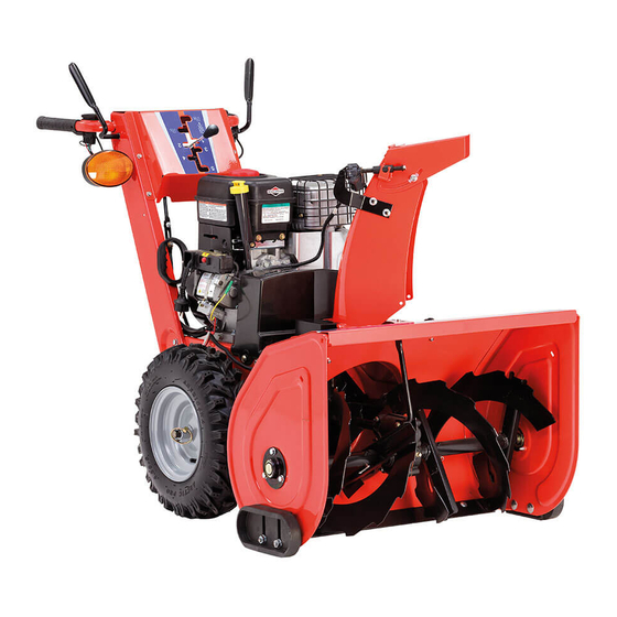
OPERATOR'S
MANUAL
Signature Professional
Series Snowthrowers
1524 Models
Mfg. No.
Description
1695303
P1524E, Snowthrower
1695304
P1524EX, Snowthrower (CE)
1628 Models
Mfg. No.
Description
1695305
P1628E, Snowthrower
1695306
P1628EX, Snowthrower (CE)
1732 Models
Mfg. No.
Description
1695307
P1732E, Snowthrower
1695308
P1732EX, Snowthrower (CE)
1738 Models
Mfg. No.
Description
1695309
P1738E, Snowthrower
1695310
P1738EX, Snowthrower (CE)
1695358
P1738E, Snowthrower
1695359
P1738EX, Snowthrower (CE)
TP 100-4585-01-LW-SN
1734900
Revision 01
Rev. Date 8/2007
Advertisement
Table of Contents

Related Manuals for Briggs & Stratton Signature Professional 1524


Summary of Contents for Briggs & Stratton Signature Professional 1524
- Page 1 OPERATOR’S MANUAL Signature Professional Series Snowthrowers 1524 Models Mfg. No. Description 1695303 P1524E, Snowthrower 1695304 P1524EX, Snowthrower (CE) 1628 Models Mfg. No. Description 1695305 P1628E, Snowthrower 1695306 P1628EX, Snowthrower (CE) 1732 Models Mfg. No. Description 1695307 P1732E, Snowthrower 1695308 P1732EX, Snowthrower (CE) 1738 Models Mfg.
-
Page 3: Table Of Contents
CONTENTS: Safety Rules & Information General...2 Training ...4 Preparation ...4 Operation...4 Children ...5 Clearing a Clogged Discharge Chute ...5 Service, Maintenance and Storage ...5 Emissions ...5 Decals...7 Safety Icons ...8 Identification Numbers...9 Features, Controls & Operation Control Locations...10 General Operation Checks Before Each Start-Up ...12 Starting Controls...13 Starting the Engine...14... -
Page 4: Safety Rules & Information
Safety Rules & Information Read the Manual The operator’s manual contains important safety information you need to be aware of BEFORE you operate your unit as well as DURING operation. Safe operating techniques, an explanation of the product’s features and controls, and maintenance information is included to help you get the most out of your equipment investment. - Page 5 Moving Parts This equipment has many moving parts that can injure you or someone else. However, if you are standing in the operator’s position, and follow all the rules in this book, the unit is safe to operate. The auger and impeller have spinning parts that can amputate hands and feet. Do not allow anyone near the equipment while it is running! DO NOT clear the discharge chute by hand.
-
Page 6: Training
Safety Rules & Information This machine is capable to amputating hands and feet and throwing objects. Read these safety rules and follow them closely. Failure to obey these rules could result in loss of control of unit, severe personal injury or death to you, or bystanders, or damage to property or equipment. -
Page 7: Children
21. Keep in mind the operator is responsible for acci- dents occurring to other people or property. 22. Data indicates that operators, age 60 years and above, are involved in a large percentage of power equipment-related injuries. These operators should evaluate their ability to operate the unit safely enough to protect themselves and others from injury. -
Page 9: Decals
DECALS This unit has been designed and manufactured to pro- vide you with the safety and reliability you would expect from an industry leader in outdoor power equipment. Although reading this manual and safety instructions it contains will provide you with the necessary basic knowl- edge to operate this equipment safely and effectively, we have placed several safety labels on the unit to remind you of this important information while you are operating... -
Page 10: Safety Icons
Decals and Safety Icons Part No. 1734786 Shift Decal - left SAFETY ICONS WARNING: READ OPERATOR’S MANUAL. Read and understand the Operator’s Manual before using this machine. DANGER: THROWN OBJECTS. This machine is capable of throwing objects and debris. Keep bystanders away. -
Page 11: Identification Numbers
Part No. xxxxxxx xxxxxxxxxxxxxxx Serial No. xxxxxxxxxx xxxxxxxxxxxxxxxxxxxxxxx kg: xxx xxxxxxxxxxxxxxxxxxxxxxx xxxxxxxxxxxxxxxxxxxxxxx kW: x.xx xxxxxxxxxxxxxxxxxxxxxxx xxxx max 20xx Identification Numbers When contacting your authorized dealer for replace- ment parts, service, or information you MUST have these numbers. Record your model name/number, manufacturer’s identi- fication numbers, and engine serial numbers in the space provided for easy access. -
Page 12: Features, Controls & Operation
Please take a moment and familiarize yourself with the name, location, and function of these controls so that you will better understand the safety and operating instructions provided in this manual. CONTROL LOCATIONS The information below briefly describes the function of individual controls. Starting, stopping, and driving require the combined use of several controls applied in specific sequences. -
Page 13: Auger Control
Auger Control Engages the auger/impeller when depressed. Releasing the control stops the auger/impeller. Chute Direction Control Models with Electric Chute Rotator: Depressing the chute rotator switch rotates the chute left or right. Models with Manual Chute Rotator: Turning the crank rotates the discharge chute to desired position. -
Page 14: General Operation
Operation GENERAL OPERATION CHECKS BEFORE EACH START-UP 1. Make sure all safety guards are in place and all nuts, bolts and clips are secure. 2. Check to make sure that the clean-out is attached to the machine. Do not operate the machine without the clean-out tool properly stored on the machine. -
Page 15: Starting Controls
STARTING CONTROLS See Figure 1 for the following instructions. Electric Start A. Electric Start Button - The Electric Start Button (A) activates an electric starter mounted to the engine, eliminating the need to pull the starter han- dle. The Electric Start Button operates on 120 Volts AC, which is provided by connection to the extension cord provided with units equipped with this feature. -
Page 16: Starting The Engine
Operation STARTING THE ENGINE WARNING Rapid retraction of starter cord (kickback) will pull hand and arm toward engine faster than you can let go. Broken bones, fractures, bruises or sprains could result. When starting engine, pull the starter cord slowly until resistance is felt and then pull rapidly to avoid kickback. -
Page 17: Stopping The Engine
4. Turn the fuel shut-off valve (B, Figure 2), if equipped, to the ON position. 5. Push in the safety key (C). 6. Turn the choke control knob (D) to the choke posi- tion. NOTE: Do not use the choke to start a warm engine. 7. -
Page 18: Operating The Snowthrower
Operation OPERATING THE SNOWTHROWER 1. Rotate the discharge chute to the desired direction. 2. Set the speed selector to the desired forward speed. 3. Fully press and hold the auger engage control (C, Figure 4) on the right-hand grip to begin auger rota- tion. -
Page 19: Deflector
DEFLECTOR The distance of the discharged snow is mainly controlled by the position of the deflector. (Engine speed also affects distance of discharge.) The more the deflector is tilted UP, the farther snow will be thrown. Models with Chute Deflector Knob See Figure 5. -
Page 20: Easy-Turn And Traction Drive Lock
Operation FULL TRACTION Both Wheels Drive Figure 8. Easy Turn Control EASY TURN™ FREEWHEELING AND TRACTION DRIVE LOCK While Clearing Snow: For easy turning when using the snowthrower, squeeze the Easy Turn™ lever (Figure 8). Engaging the Easy Turn™ lever releases the right traction wheel but allows the left wheel to continue driving (Figure 8). -
Page 21: After Each Use
AFTER EACH USE Normal use of the snowthrower may result in a build-up of packed snow in and around the starter cord housing and around engine controls. Heat from the engine will usually prevent the snow from freezing solid while the unit is running, but after the engine is shut down, some snow may continue melting from engine heat, and later freeze around some moving parts as the unit cools. -
Page 22: Regular Maintenance
MAINTENANCE SCHEDULE Maintenance Required Check auger gear case lubrication.** Lubricate snowthrower. Check tire pressure. Change engine oil.* ✛ Clean or replace spark plug. Check drive linkage / belt tension. Lubricate axle shafts. Check / lubricate free-hand linkage. Lubricate auger shaft.*** * Change original oil after two hours of operation. -
Page 23: Lubrication
LUBRICATION IMPORTANT NOTE It is very important that grease fittings on the auger shaft are lubricated regularly. If auger rusts to shaft, damage to worm gear may occur if shear pins do not break. To prevent wheels rusting to axles, it is also necessary to remove the wheels and grease the axles regularly. -
Page 24: Check / Lubricate Free-Hand Linkage
Regular Maintenance CHECK / LUBRICATE FREE-HAND LINKAGE Check the function of the Free-Hand controls: the con- trols should function as described in the CONTROLS section. It is critical for the safe operation of the unit that the controls disengage when released. Lubricate as shown in Figures 16-17. -
Page 25: Troubleshooting, Adjustments & Service
Troubleshooting, Adjustments & Service TROUBLESHOOTING This section provides troubleshooting and service instructions. Locate the problem and check the possible cause/remedy in the order listed. Also, refer to the Engine Owner’s Manual for additional information. For problems not covered here, contact your local deal- Problem Engine fails to start. - Page 26 Troubleshooting Problem Auger rotates, but snow is not- thrown far enough. Poor traction. Auger does not stop when auger lever is released. Snowthrower does not stop- when drive lever is released. Discharge control is difficult to operate. Snowthrower veers to one side.
-
Page 27: Speed Selector Adjustment
SPEED SELECTOR ADJUSTMENT 1. Loosen the two nuts (C, Figure 19). 2. Place the shift lever in 5th gear. 3. Push the lower rod into the housing and tighten the two nuts (C). Do not lift up or down on rods while tightening. -
Page 28: Traction Drive Tension
Adjustments TRACTION DRIVE TENSION Initial Adjustment 1. Lift the bellcrank arm (C, Figure 21) up as far as it will 2. While holding the bell crank arm (C) up, adjust the cable until all the slack is removed. 3. Back the adjustment screw (E) out 7-8 turns. Tighten nut (D). -
Page 29: Manual Discharge Chute Adjustment
MANUAL DISCHARGE CHUTE CONTROL LINKAGE ADJUSTMENT Pinion Gear Adjustment If the discharge chute is difficult to operate, first lubricate the pinion gear (A, Figure 22) and ring gear (F). If it is still difficult to operate, adjust as follows: NOTE: If the discharge chute will not stay in position, adjust the pinion gear (A) closer to the ring gear (F). -
Page 30: Easy Turn Cable Adjustment
Adjustments & Service EASY TURN™ CABLE ADJUSTMENT If the Easy Turn™ cable has stretched, the gears will not disengage when the control lever is activated. Adjust the cable using the following procedure. 1. Turn the engine off and disconnect the spark plug wire. -
Page 31: Belt Replacement
BELT REPLACEMENT 1. Turn off the engine, remove the spark plug wire, and wait for all moving parts to stop. Rotate the spout full right. Loosen the two screws (B, Figure 27) securing the belt cover. 2. Tilt the cover forward and work it off the snowthrower. 3. - Page 32 Service 6. Reverse the procedure to install the belts. Be sure there are no twists and the belts are properly seated in the grooves. Adjust the belt stops so there is 1/8” (3mm) clearance between belt and stop. The pattern for both belts is shown in Figure 30.
-
Page 33: Specifications
20.87 cu. in. (342 cc) Oil Capacity 28 oz. (,84 l) Specifications CHASSIS: Wheels - 1524, 1628 Tire Size: 16 x 4.8 Inflation Pressure: 20 psi (1,37 bar) - 1732, 1738 Tire Size: 16 x 6.5 Inflation Pressure: 14 psi (,96 bar) -
Page 34: Parts & Accessories
REPLACEMENT PARTS Replacement parts are available from your authorized dealer. Always use genuine Simplicity / Snapper Service Parts. MAINTENANCE ITEMS Many convenient and helpful service and maintenance items are available from you authorized dealer. Some of these items include: Engine Oil Tire Sealant Touch-Up Paint Degrimer/Degreaser... - Page 36 M A N U F A C T U R I N G , I N C . 500 N Spring Street / PO Box 997 Port Washington, WI 53074-0997 www.SimplicityMfg.com P R O D U C T S , I N C . 535 Macon Street McDonough, GA 30253 www.Snapper.com...