Table of Contents
Advertisement
Quick Links
Advertisement
Table of Contents

Related Manuals for Novatel MarinePak7


Summary of Contents for Novatel MarinePak7
- Page 1 MarinePak7 User Manual December 2020 OM-20000188 1...
- Page 2 Information in this document is subject to change without notice and does not represent a commitment on the part of NovAtel Inc. The software described in this document is furnished under a licence agreement or non-disclosure agreement. The software may be used or copied only in accordance with the terms of the agreement.
-
Page 3: Table Of Contents
2.8.1 MarinePak7 Siting Guidelines 2.8.2 Ceiling Mount 2.9 Connect Power to the MarinePak7 2.9.1 Connect the MarinePak7 to AC Power Source 2.9.2 Connect the MarinePak7 to a DC Power Source 2.9.3 MarinePak7 Internal Battery 2.10 Cellular Antenna Installation 2.11 Communication with the MarinePak7 2.11.1 LCD User Interface... - Page 4 4.6 UHF Radio 4.6.1 UHF Radio Status Tile 4.6.2 UHF Radio Configuration Tile 4.7 MSK Beacon 4.7.1 MSK Beacon Status Tile 4.7.2 MSK Beacon Configuration Tile 4.8 Serial Ports 4.8.1 COM Ports Tile 4.8.2 Log List Tile MarinePak7 User Manual 1...
- Page 5 4.11.8 Saving Mode 4.11.9 System Setting APPENDIX A MarinePak7 Technical Specifications A.1 MarinePak7 Performance Specifications A.2 MarinePak7 Mechanical Specifications A.3 MarinePak7 Electrical and Environmental Specifications A.4 MarinePak7 Data Communications Specifications A.5 MarinePak7 Strobe Specifications A.6 MSK Beacon Receiver Specifications A.7 GSM Specifications A.8 UHF Radio Specifications...
-
Page 6: Regulatory And Compliance
The product has been designed and manufactured in accordance with RoHS Directive (2011/65/EU) BS EN 50581:2012 and (2015/863) EN IEC 63000:2018 with all components being RoHS compliant. MarinePak7 Radio Transmission and Antenna Requirements UHF Radio The radio module used in this device has been designed to operate in the 410-475 MHz and 902-928 MHz frequency bands, the exact use of which differs from one region and/or country to another. - Page 7 Antenna types not included in this list or having a gain greater than the maximum gain indicated from that type, are strictly prohibited for use with this device. Australia (AU) – The authorised operating band is limited to 915 – 928 MHz. MarinePak7 User Manual 1...
- Page 8 Antenna types not included in this list or having a gain greater than the maximum gain indicated from that type, are strictly prohibited for use with this device. Antenna Type Manufacturer Antenna Model Maximum Gain (dBi) Omnidirectional Siretta Ltd. DELTA25/X/SMAM/S/RA/35 MarinePak7 User Manual 1...
-
Page 9: Customer Support
Customer Support NovAtel Knowledge Base If you have a technical issue, visit the NovAtel Support page at novatel.com/support/. Through the Support page, you can contact Customer Support, find papers and tutorials or download current manuals and the latest firmware. Before Contacting Customer Support... -
Page 10: Chapter 1 Introduction
From these observations, the receiver can compute position and velocity with high accuracy. With Precise Point Positioning (PPP) and Oceanix corrections, or differential GNSS, positioning can be accurate to within a few centimeters. For a detailed discussion of GNSS, refer to NovAtel’s book Introduction to GNSS available from our web site. -
Page 11: Manual Scope
The USB and Wi-Fi antenna connectors are on the front of the MarinePak7. 1.2 Manual Scope This manual contains information about the installation and operation of the MarinePak7 system. It is beyond the scope of this manual to provide details on service or repair. For any customer-service related inquiries, refer to Customer Support on page 9. - Page 12 Chapter 1 Introduction A caution that actions, operation or configuration may lead to incorrect or improper use of the hardware. A warning that actions, operation or configuration may result in regulatory noncompliance, safety issues or equipment damage. MarinePak7 User Manual 1...
-
Page 13: Chapter 2 Marinepak7 Installation
For the receiver to perform optimally, the following user-supplied additional equipment is required: At least one quality, dual-frequency GNSS antenna (such as the NovAtel V560 Marine Antenna).. A second GNSS antenna is required to use the MarinePak7 ALIGN heading functionality. -
Page 14: Selecting A Gnss Antenna
MSK beacon corrections are required. The NovAtel V560 marine antenna is an example of an antenna that can receive GNSS, L-band and MSK beacon signals. NovAtel offers a variety of GNSS antennas with band pass filtering and an LNA (refer to our web site: novatel.com/products/antennas for details of available antennas). -
Page 15: Choosing A Coaxial Cable
NovAtel offers several coaxial cables to meet GNSS antenna interconnection requirements, including: 5, 15, or 30 m antenna cables with TNC male connectors on both ends (NovAtel part numbers C006, C016 and C032 respectively) - Page 16 5. Connect the Wi-Fi antenna to the Wi-Fi port on the front of the MarinePak7. 6. If the MarinePak7 is using a UHF radio to receive correction data, connect a coaxial cable from the UHF antenna to the UHF TNC connector on the MarinePak7.
-
Page 17: Mounting The Gnss Antenna
MarinePak7 to the devices using the I/O signal. 11. Connect the 12V DC power supply to the 4 pin DC connector on the back of the MarinePak7 and then connect the power supply to the mains outlet. -
Page 18: Ceiling Mount
MarinePak7 can be secured to a flat surface, such as a shelf, using four screws. The mounting shroud can be moved to the bottom of the MarinePak7 to allow the MarinePak7 to be mounted on a ceiling. To ceiling mount the MarinePak7: 1. -
Page 19: Connect The Marinepak7 To Ac Power Source
The MarinePak7 can be powered by a DC power source that provides a voltage of 12 to 24 VDC. 1. Connect a cable with a 4 pin LEMO connector on one end to the DC connector on the MarinePak7. 2. Connect the other end of the cable to at DC power source that provides 12 to 24 VDC. -
Page 20: Cellular Antenna Installation
MarinePak7. 2.10 Cellular Antenna Installation The MarinePak7 has a cellular antenna port to facilitate the connection of an external cellular antenna. An external antenna must be connected to this port in order to use the integrated cellular radio. -
Page 21: Communication With The Marinepak7
2.11.1 LCD User Interface The LCD screen and navigation buttons on the front of the MarinePak7 are used to monitor the receiver status, access receiver data and configure the MarinePak7. For information about using the LCD User Interface, see LCD User Interface on page 23. -
Page 22: Icom Ports
The GSM cellular modem status can be viewed from the LCD UI (see GSM Status on page 43). 2.11.7 UHF Radio A UHF radio is available on some models of the MarinePak7 which operates in the 410-475 MHz and 902- 928 MHz bands. This radio is typically used to receive RTK correction data. -
Page 23: Chapter 3 Configure The Marinepak7 Using The Lcd Ui
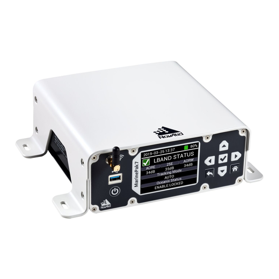
Interface (LCD UI). 3.1 LCD User Interface The MarinePak7 LCD UI consists of an LCD screen and several navigation buttons. From the LCD UI, you can monitor the status of the receiver and configure the receiver settings. Figure 5: MarinePak7 UI Screen... -
Page 24: Position Status
Press the Home button from any screen to return to the Position Status (Home) screen. Button 3.2 Position Status The Position Status (Home) screen displays the position status of the MarinePak7. Position Status Icon displays GREEN when the receiver reports SOLUTION_COMPUTED. - Page 25 Chapter 3 Configure the MarinePak7 Using the LCD UI Table 4: Solution Status Status Description SOL_ Solution computed COMPUTED INSUFFICIENT_ Insufficient observations No convergence CONVERGENCE SINGULARITY Singularity at parameters matrix COV_TRACE Covariance trace exceeds maximum (trace > 1000 m) TEST_DIST Test distance exceeded (maximum of 3 rejections if distance >10 km)
- Page 26 Chapter 3 Configure the MarinePak7 Using the LCD UI Table 5: Position Type Mode Description NONE No solution FIXEDPOS Position has been fixed by the user entering the position or by position averaging. FIXEDHEIGHT Position has been fixed by the user entering the position or by position averaging...
-
Page 27: Position Configuration
Chapter 3 Configure the MarinePak7 Using the LCD UI Mode Description PPP_ Converging Oceanix solution CONVERGING Converged Oceanix solution OPERATIONAL Solution accuracy is within UAL operational limit WARNING Solution accuracy is outside UAL operational limit but within warning limit OUT_OF_BOUNDS... -
Page 28: Base Station Configuration
Chapter 3 Configure the MarinePak7 Using the LCD UI Correction Src Press the Left or Right arrow on the keypad to scroll through the correction source options. Enable MSK DGPS receiver module and RTCM correction format (Receive only). Enable Satel UHF radio module. -
Page 29: Heading Status
The value range for the longitude is -180 to +180 (degrees). Height (MSL) Use the Up and Down arrows to change the height of the MarinePak7 relative to mean sea level. The value range for the height is -1000 to +20000000 (meters) After entering the base station coordinates, the position type will display FIXEDPOS and correction messages will start transmitting from the selected output port. -
Page 30: Heading Configuration
Press the Enter button to save the configuration. Heading Offset The Heading Offset parameters are used to add an offset in the heading values reported by the MarinePak7. The unmodified heading value represents the angle from True North of the base to rover vector in a clockwise direction. -
Page 31: Ins Configuration
Chapter 3 Configure the MarinePak7 Using the LCD UI The INS screen is only visible when the MarinePak7 is loaded with a SPAN firmware model. The INS Status and INS CONFIG screens are not visible when the MarinePak7' is in Base Station mode. - Page 32 Chapter 3 Configure the MarinePak7 Using the LCD UI Use the Up and Down arrow buttons to select the INS configuration option. Move to the parameter that is to be configured and press the Enter button to enable EDIT MODE<>. Use the arrow buttons to change the configuration.
-
Page 33: Gnss Status
Chapter 3 Configure the MarinePak7 Using the LCD UI 3.5 GNSS Status The GNSS Status screen provides information about the GNSS solution. To access the GNSS Status screen from the Position Status (Home) screen, press the Right arrow until the GNSS Status screen displays. -
Page 34: Gnss Configuration
3.6 LBAND Status The LBAND Status and LBAND Configuration screens are not visible when the MarinePak7' is in Base Station mode. You must change the MarinePak7 mode to Rover in the System Configuration on page 53 screen to access LBAND screens. - Page 35 Up to 3 beam IDs will be displayed when the tracking mode is set to AUTO. Only one beam ID is displayed when a beam is manually selected. Tracked beam Displays the real-time C/No (dB-Hz) levels of the transmission beam(s) the MarinePak7 is (s) C/No tracking.
-
Page 36: Lband Configuration
Chapter 3 Configure the MarinePak7 Using the LCD UI Oceanix Status Displays the status of the Oceanix subscription. Access ENABLE Subscription is valid DISABLE Subscription is not valid Status NO_SIGNAL None of the decoders have received data in the last 30 seconds. -
Page 37: Msk Status
Position Status screen. 3.7 MSK Status The MSK Status and MSK Configuration screens are not visible when the MarinePak7' is in Base Station mode. You must change the MarinePak7 mode to Rover in the System Configuration on page 53 screen to access MSK screens. -
Page 38: Msk Configuration
Chapter 3 Configure the MarinePak7 Using the LCD UI To access the MSK Status screen from the Home screen, press the Right arrow button until the MSK Status screen displays. Status Indicator Displays green when the MSK module is locked onto a valid correction source. -
Page 39: Uhf Status
Chapter 3 Configure the MarinePak7 Using the LCD UI Use the Up and Down arrow buttons to select the MSK configuration option. Move to the parameter that is to be configured and press the Enter button to enable EDIT MODE<>. Use the arrow buttons to change the configuration. -
Page 40: Uhf Configuration
Chapter 3 Configure the MarinePak7 Using the LCD UI To access the UHF Status screen from the Home screen, press the Right arrow button 4 times. Status Indicator Displays GREEN when the UHF module is active. Signal Power Displays the UHF reception signal power. - Page 41 Chapter 3 Configure the MarinePak7 Using the LCD UI Use the Up and Down buttons to navigate between the configuration options. Move to the parameter that is to be configured and press the Enter button to enable EDIT MODE<>. Use the arrow buttons to change the configuration.
- Page 42 Chapter 3 Configure the MarinePak7 Using the LCD UI Compatibility Link Rate (bps) / Channel Spacing Protocol Modulation Mode (kHz) Satel 3AS 4FSK 9600 / 12.5 Pacific Crest compatible GMSK 9600 / 25.0 Pacific Crest compatible GMSK 9600 / 25.0...
-
Page 43: Gsm Status
Status screen. 3.9 GSM Status The GSM Status screen is not visible when the MarinePak7' is in Base Station mode. You must change the MarinePak7 mode to Rover in the System Configuration on page 53 screen to access GSM Status screen. -
Page 44: Serial Status
Chapter 3 Configure the MarinePak7 Using the LCD UI Signal Power Displays the signal strength of the cellular reception. Mode Displays the cellular connection mode (3G/4G). Operator Displays the cellular network operator 3.10 Serial Status The Serial Status screen displays the status of the receiver's serial (COM) ports. -
Page 45: Serial Configuration
Chapter 3 Configure the MarinePak7 Using the LCD UI Serial Line Displays the COM port line standard (RS232/RS422). Standard Baud Rate Displays the COM port baud rate. Serial Displays the COM port communication settings (data bits, parity, stop bits). Protocol... - Page 46 Chapter 3 Configure the MarinePak7 Using the LCD UI Port settings 1. Use the Left or Right arrow buttons to select the port parameter. 2. Press the Enter button to access the parameter options. 3. Use the Left or Right arrow buttons to select the required parameter option.
-
Page 47: Net Port Status
Chapter 3 Configure the MarinePak7 Using the LCD UI NMEA Messages When selecting NMEA as the output protocol you need to choose the NMEA messages and data output rate. When NMEA is highlighted press the Enter button to access the NMEA message selection option. Use the Left or Right buttons to scroll through the NMEA messages available. -
Page 48: Net Port Configuration
Chapter 3 Configure the MarinePak7 Using the LCD UI To access the Network Status screen from the Home screen, press the Right arrow until the Network Status screen displays. The following parameters are available for each ICOM port. Protocol The protocol used by the ICOM port. - Page 49 Chapter 3 Configure the MarinePak7 Using the LCD UI Use the Up and Down buttons to navigate between the configuration options. Move to the parameter that is to be configured and press the Enter button to enable EDIT MODE<>. Use the arrow buttons to change the configuration.
-
Page 50: Network Status
Chapter 3 Configure the MarinePak7 Using the LCD UI GPHDT NMEA Heading Log (ALIGN) GPRMC GPS Specific Information GPVTG Track Made Good and Ground Speed GPZDA UTC Time and Date Press the Enter button to access the data output rate options. The available data output rates (in seconds) are: 1, 2, 5, 10, 20, 50, 100. -
Page 51: Network Configuration
Chapter 3 Configure the MarinePak7 Using the LCD UI IP Address IP address of the receiver. Netmask Netmask for the receiver. Gateway IP address for the gateway. 3.12.1 Network Configuration From the Network Status screen, press the Enter button to access the Network configuration screen. -
Page 52: System Status
Chapter 3 Configure the MarinePak7 Using the LCD UI After all the configuration options have been set, press the Enter button to accept the changes and save the settings to the receiver. Press the Back button to return to the Network Status screen. Press the HOME button to return to the HOME screen. -
Page 53: System Configuration
Chapter 3 Configure the MarinePak7 Using the LCD UI 3.13.1 System Configuration From the System Status screen, press the Enter button to access the System configuration screen. Use the Up and Down buttons to navigate between the configuration options. Move to the parameter that is to be configured and press the Enter button to enable EDIT MODE<>. - Page 54 Chapter 3 Configure the MarinePak7 Using the LCD UI 3. Press the Left or Right buttons to make a selection. On Enables antenna power to the GNSS2 port. This port connects to the secondary GNSS antenna. Off Disables power to the GNSS1 port.
-
Page 55: System Information
Chapter 3 Configure the MarinePak7 Using the LCD UI Solution Description Mode Type NARROW_ ROVER NARROW_INT is achieved when compatible and valid RTK corrections are SINGLE received. FIX position solution is achieved when the base station coordinates are input into... - Page 56 Chapter 3 Configure the MarinePak7 Using the LCD UI Model Displays the purchased firmware model of the OEM7 GNSS receiver. Software Displays the MarinePak7 software version. Firmware Displays the firmware version of the OEM7 GNSS receiver. Displays the Product Activation Code for the OEM7 GNSS receiver. The PAC is required when ordering Oceanix subscriptions.
-
Page 57: Chapter 4 Web User Interface
4.1 Open the Web UI Once the receiver is connected and powered, use a Wi-Fi capable device to locate the MarinePak7 in the list of detected Wi-Fi Networks and establish a connection. The MarinePak7 SSID is printed on a label on the side of the receiver. -
Page 58: Dashboard
4 healthy satellites then the red warning icon displays. When the icon is red, the receiver cannot compute a valid position. Logging Displays when global logging is off. Status Displays when global logging is on. MarinePak7 User Manual 1... -
Page 59: Module Status Tile
Chapter 4 Web User Interface 4.3.2 Module Status Tile Provides the status of the radio modules in the MarinePak7. Displays green when the UHF module is active and is receiving data via the UHF module. Displays red when the UHF module is not active. -
Page 60: Gnss Position Tile
The number of GNSS satellites being tracked and the number of GNSS satellite used in the computed solution. All accuracy values are in RMS. Table 6: Solution Status Value Description SOL_ Solution computed COMPUTED INSUFFICIENT_ Insufficient observations MarinePak7 User Manual 1... - Page 61 Value Description NONE No solution Position has been fixed by the FIX position command or by position FIXEDPOS averaging. Position has been fixed by the FIX height or FIX auto command or by FIXEDHEIGHT position averaging MarinePak7 User Manual 1...
- Page 62 Solution accuracy is outside UAL operational limit but within warning limit OUT_OF_BOUNDS Solution accuracy is outside UAL limits INS_PPP_CONVERGING INS with Oceanix Precise Point Positioning (PPP) solution converging INS_PPP INS with Oceanix PPP solution PPP_BASIC_CONVERGING Converging TerraStar-L solution MarinePak7 User Manual 1...
-
Page 63: Carrier To Noise Tile
This tile provides a graphical plot of the receiver L1 and L2 carrier to noise ratio. This tile is updated once per second. 4.3.6 Position Accuracy Tile Graphical view of the receiver 2D and 3D accuracy, updated at 1 Hz. MarinePak7 User Manual 1... -
Page 64: Standard Deviation Tile
Graphical view of the receiver standard deviations for latitude, longitude and height, updated at 1 Hz. 4.4 GNSS Receiver This page has several tiles that provide detailed information about the GNSS receiver. From this page, the following GNSS receiver configuration settings can be adjusted: Receiver Configurable Parameters NTRIP Ethernet Heading MarinePak7 User Manual 1... -
Page 65: Gnss Status Tile
PDOP represents the uncertainty of the 3D parameters (latitude, longitude, height). VDOP Vertical Dilution of Precision of the computed solution. VDOP represents the uncertainty of the height parameter. 4.4.2 Position Status Tile Provides information about the computed solution. MarinePak7 User Manual 1... -
Page 66: Details Tile
The active position mode type. See Table 5: Position Type on page 26. 4.4.3 Details Tile Serial Number Serial number of OEM7 GNSS receiver board inside the MarinePak7. Firmware Version Firmware version of the OEM7 GNSS receiver board. MarinePak7 User Manual 1... -
Page 67: Receiver Configurable Parameters Tile
Purchased firmware model loaded on the GNSS receiver board. 4.4.4 Receiver Configurable Parameters Tile This tile displays the active differential position configuration settings. Click on the Edit icon to enter the configuration window. To configure the receiver parameters: MarinePak7 User Manual 1... -
Page 68: Ntrip Tile
Enable MSK DGPS receiver module and RTCM correction format (Receive only). Enable Satel UHF radio module. Enable GSM module and cellular corrections (subscription required). NCOM Enable MarinePak7 NCOM port. 2. From the Correction Format drop menu, select the correction format used. NOVATELX NOVATELX correction format... - Page 69 TCP/UDP port number (default = 80) Mount Maximum 80 The mount point to use Point character string User Enter the NTRIP connection User Name Name Password Enter the NTRIP connection password, if required. MarinePak7 User Manual 1...
-
Page 70: Ethernet Tile
4.4.6 Ethernet Tile This tile displays the Ethernet settings for the MarinePak7. Click on the Edit icon to enter the configuration window. 1. In the IP box, enter the IP address for the MarinePak7. 2. Click Save changes. 4.4.7 PPS Tile The PPS tile displays the active PPS Control settings. -
Page 71: Lband
The LBand page provides information about the Oceanix subscription and L-band signal strength. The parameters for LBand tracking can be changed from this page. 4.5.1 LBand Status Tile This tile provides status information about the L-band signals. MarinePak7 User Manual 1... -
Page 72: Lband Details Tile
Displays the Product Activation Code for the OEM7 GNSS receiver The PAC is required when ordering Oceanix subscriptions.. OEM Serial The serial number that identifies the OEM7 GNSS receiver board in the MarinePak7. Number 4.5.3 L-band Configuration Tile The L-band configuration tile displays the receiver’s active Oceanix configuration status. -
Page 73: Uhf Radio
Leave this text box blank to use the default baud rate. 2. In the Frequency text box, enter the Beam Frequency in Hz. Leave this text box blank to use the default frequency. 4.6 UHF Radio The UHF Radio page displays information about the UHF radio. MarinePak7 User Manual 1... -
Page 74: Uhf Radio Status Tile
Display the current UHF radio protocol. Data Rate Displays the UHF radio transmission data rate. Displays the Forward Error Correction (FEC) setting. Channel Displays the selected UHF channel. Frequency Displays the radio frequency of the selected UHF channel. MarinePak7 User Manual 1... -
Page 75: Uhf Radio Configuration Tile
Link Rate (bps) / Channel Spacing Protocol Modulation Mode (kHz) Pacific Crest compatible GMSK 4800 / 12.5 Pacific Crest compatible GMSK 4800 / 12.5 Pacific Crest compatible 4FSK 9600 / 12.5 Pacific Crest compatible 4FSK 9600 / 12.5 MarinePak7 User Manual 1... -
Page 76: Msk Beacon
Trimtalk compatible GMSK 9600 / 25.0 Trimtalk compatible GMSK 16000 Satel 3AS 4FSK 19200 / 25.0 Satel 3AS 4FSK 19200 / 25.0 4.7 MSK Beacon This page displays the MSK Radio Beacon details and settings. MarinePak7 User Manual 1... -
Page 77: Msk Beacon Status Tile
The tracking mode active on the MSK module (Auto or Manual). Frequency The Frequency setting of the MSK module. 4.7.2 MSK Beacon Configuration Tile This tile displays the MSK Beacon configuration status. Click on the Edit icon to enter the configuration window. MarinePak7 User Manual 1... -
Page 78: Serial Ports
These parameters can also be edited from this page. 4.8.1 COM Ports Tile The COM port tile displays the COM port configuration for the receiver’s serial ports. Click the Edit icon to open the COM port configuration window. MarinePak7 User Manual 1... - Page 79 Use RS422 protocol on this COM port. Baud rate 2400, 4800, 9600, 19200, 38400, Select the baud rate used on this COM port. 57600, 115200, 230400, 460800 Stop Bits Use one stop bit Use two stop bits MarinePak7 User Manual 1...
-
Page 80: Log List Tile
None, NovAtel, RTCM, RTCMV3, Select the data protocol transmitted 4.8.2 Log List Tile The Log List tile displays the logs currently being output on each COM port. Click the Edit icon to open the Edit Log Configuration window. MarinePak7 User Manual 1... -
Page 81: Net Ports
COM3 Message Message ID of Select the Message ID of the log to be output on this COM port. the log The logs can be NMEA standard or NovAtel logs. For the list of the logs available, see docs.novatel.com/OEM7/Content/Logs/NMEA_Standard_ Logs_.htm Type ASCII, Binary Select the output format for the log. -
Page 82: Net Ports Tile
Chapter 4 Web User Interface 4.9.1 NET Ports Tile The NET Ports tile displays the configuration for the receiver’s network (ICOM) ports. Click the Edit icon to open the NET port configuration window. MarinePak7 User Manual 1... - Page 83 3. Click the Input Data drop menu and select the message protocol accepted through this ICOM port. NONE The port is disabled. It accepts no messages. NOVATEL The port accepts NovAtel commands and logs. NOVATELX The port accepts NOVATELX corrections. RTCMV3 The port accepts RTCM Version 3.0 corrections.
-
Page 84: Logging
4.10.1 Global Logging Status The Global Logging Status tile controls whether logging to the MarinePak7 internal storage is enabled (On) or disabled (Off). Setting the Global Logging Status to OFF disables user selected logs from being stored to the internal memory. -
Page 85: Usage Details
Use this tile to download the logs stored on internal data storage. This tile is also used to erase data from internal data storage. To download the logs: 1. Insert a USB stick into the USB port on the front of the MarinePak7. 2. Click the Download User Log button. To erase the stored logs: 1. -
Page 86: System
If the ONTIME Trigger is selected, enter the amount of time, in seconds, 2, 1, 0.5, 0.2, between logs. 0.1, 0.05 Required for the ONTIME trigger only. 4.11 System This page provides information about the MarinePak7 system and provides access to the firmware upload feature. MarinePak7 User Manual 1... -
Page 87: Status
The Screen tile show the brightness setting of the LCD interface screen. To change the LCD screen brightness: 1. Click the Edit (pencil) icon. 2. The Edit Screen Configuration dialog box appears. 3. Use the slider to set the LCD screen brightness. 4. Click Save changes. MarinePak7 User Manual 1... -
Page 88: Antenna Rf2
Once the upload is complete, the MarinePak7 will restart. 4.11.8 Saving Mode The Saving Mode tile sets the behavior of the MarinePak7 when it is running on battery power only. To change the Saving Mode parameters: 1. Click the Edit (pencil) icon. -
Page 89: System Setting
Battery Level 3. Click Save changes. 4.11.9 System Setting The System Setting tile provides an option to reset the MarinePak7 settings to factory default values. To reset the MarinePak7 settings to factory defaults: 1. Click Restore to default values. A confirmation screen appears. -
Page 90: Appendix A Marinepak7 Technical Specifications
MSK Beacon Receiver Specifications on page 103 UHF Radio Specifications on page 104 MarinePak7 Connectors on page 104 For information about the cables available for the MarinePak7, see the following: Serial Data Cable on page 108 DC Power Cable on page 110 MarinePak7 User Manual 1... -
Page 91: Marinepak7 Performance Specifications
GNSS system characteristics, Signal-in-Space (SIS) operational degradation, ionospheric and tropospheric conditions, satellite geometry, baseline length, multipath effects and the presence of intentional or unintentional interference sources. GPS-only. Requires a Oceanix subscription which is available direct from NovAtel (novatel.com/products/correction- services/oceanix-correction-services). Performance dependent on local observing conditions. - Page 92 APPENDIX A MarinePak7 Technical Specifications L1 C/A, L1C, L2C, L2P, L5 L1 C/A, L2 C/A, L2P, L3, L5 GLONASS Signals Tracked Galileo E1, E5 AltBOC, E5a, E5b Secondary Antenna (GNSS2) BeiDou B1I, B1C, B2I, B2a NavIC (IRNSS) QZSS L1 C/A, L1C, L2C, L5 Hot: <19 s (almanac and recent ephemeris saved and approximate position and...
- Page 93 APPENDIX A MarinePak7 Technical Specifications Code Carrier L1 C/A 4 cm 0.5 mm L2 P(Y) 8 cm 1.0 mm 8 cm 0.5 mm 3 cm 0.5 mm L1 C/A 8 cm 1.0 mm GLONASS L2 P 8 cm 1.0 mm...
-
Page 94: Marinepak7 Mechanical Specifications
A.2 MarinePak7 Mechanical Specifications MarinePak7 Dimensions – Top below MarinePak7 Dimensions – Front below MarinePak7 Dimensions – Back on the next page MarinePak7 Dimensions – Side on the next page MarinePak7 Mounting Shroud Tabs on page 96 MarinePak7 Mounting Holes on page 97 The dimensions in the following figures are in millimeters. - Page 95 APPENDIX A MarinePak7 Technical Specifications Figure 8: MarinePak7 Dimensions – Back Figure 9: MarinePak7 Dimensions – Side MarinePak7 User Manual 1...
- Page 96 APPENDIX A MarinePak7 Technical Specifications Figure 10: MarinePak7 Mounting Shroud Tabs MarinePak7 User Manual 1...
- Page 97 APPENDIX A MarinePak7 Technical Specifications Figure 11: MarinePak7 Mounting Holes MarinePak7 User Manual 1...
-
Page 98: Marinepak7 Electrical And Environmental Specifications
APPENDIX A MarinePak7 Technical Specifications A.3 MarinePak7 Electrical and Environmental Specifications Table 10: MarinePak7 Power Requirements Voltage 12 – 24 VDC Minimum Typical 12 W Power Consumption Maximum 36 W (In Charge State) Table 11: Battery Specifications Manufacturer Inspired Energy... - Page 99 IEC 60945 Table 13: MarinePak7 Regulatory Compliance Compliance FCC, CE, IEC 60945 (Protected), AZ/NSZ Table 14: MarinePak7 RF Input/LNA Power Output Antenna Connectors TNC female, 50 Ω nominal impedance HDR disabled +15 dB to + 40 dB, 26 dB typical...
-
Page 100: Marinepak7 Data Communications Specifications
APPENDIX A MarinePak7 Technical Specifications A.4 MarinePak7 Data Communications Specifications Table 15: Data Communications Interfaces COM1 Electrical format RS-232/RS-422 2400, 4800, 9600, 19200, 38400, 57600, 115200, 230400 or 460800 bit/s Data rates Default = 9600 COM1_Tx, COM1_Rx, COM1_RTS, COM1_CTS (RS-232) - Page 101 APPENDIX A MarinePak7 Technical Specifications Data rates Hi-speed (480 Mb/s) Port USB Type A ETHERNET Physical layer 10BASE-T/100BASE-TX Port RJ45 Wi-Fi Wi-Fi Module Texas Instruments WL1835MOD Band 2400 MHz Transmission Power 0.0549 W (Max) Security WPA2 Encryption Port SMA 50Ω MarinePak7 User Manual 1...
-
Page 102: Marinepak7 Strobe Specifications
APPENDIX A MarinePak7 Technical Specifications A.5 MarinePak7 Strobe Specifications All of the MarinePak7 strobe signals are available on the I/O connector. Table 16: MarinePak7 Strobes Description Factory Strobes Input/Output Comment Default Input marks for which a pulse greater than 150 ns triggers certain Input logs to be generated. -
Page 103: Msk Beacon Receiver Specifications
APPENDIX A MarinePak7 Technical Specifications A.6 MSK Beacon Receiver Specifications Table 18: Receiver Module Channels 2-channel parallel tracking Frequency Range 283.5 to 325.0 kHz Channel Spacing 500 Hz Demodulation Minimum Shift Keying (MSK) MSK Bit Rates 50, 100 and 200 bps Cold Start Time <... -
Page 104: Uhf Radio Specifications
Band 902 – 928 MHz Transmission Power (Max) Modulation 4-GFSK, GMSK Port TNC 50Ω A.9 MarinePak7 Connectors The following tables provide the pinouts for the MarinePak7 connectors. A.9.1 COM Ports Table 21: COM1 Pinout RS-232 RS-422 Signal Name Description Signal Name Description... - Page 105 APPENDIX A MarinePak7 Technical Specifications RS-232 RS-422 Signal Name Description Signal Name Description No connection No connection Signal ground Signal ground No connection No connection Request to Send TxD- Transmit data – negative Clear to Send RxD- Receive data – negative No connection...
-
Page 106: Dc Power Port
APPENDIX A MarinePak7 Technical Specifications RS-232 RS-422 Signal Name Description Signal Name Description Transmit data TxD+ Transmit data – positive No connection No connection Signal ground Signal ground No connection No connection Request to Send TxD- Transmit data – negative Clear to Send RxD- Receive data –... - Page 107 APPENDIX A MarinePak7 Technical Specifications Table 25: I/O Pinout Signal Name Description Reserved Reserved Reserved Reserved Signal ground Reserved Reserved Reserved Reserved Signal ground Programmable variable frequency output ranging EVENTOUT4 from 0 Hz to 50 MHz EVENTIN1 Input mark for which a pulse greater than 150 ns triggers certain logs to be generated...
-
Page 108: Serial Data Cable
APPENDIX A MarinePak7 Technical Specifications A.10 Serial Data Cable This cable connects a device with a DB9 serial port, such as a computer, to the COM1, COM2 or COM3 port on the MarinePak7. Figure 12: Serial Data Cable Table 26: Serial Data Cable Pinout... -
Page 109: Power Supply
APPENDIX A MarinePak7 Technical Specifications A.11 Power Supply The Power Supply connects the MarinePak7 to the mains supply. The connector on the mains supply side of the Power Supply varies depending on the region in which the Power Supply is intended to be used. -
Page 110: Dc Power Cable
APPENDIX A MarinePak7 Technical Specifications A.12 DC Power Cable This cable connects the MarinePak7 to a DC power supply. Figure 14: DC Power Cable Table 27: DC Power Cable Pinout Connector A Pin Signal Name Flying Lead Wire Color Power... - Page 111 MarinePak7 User Manual 1...