
Related Manuals for Asus DSBF-D Series


Summary of Contents for Asus DSBF-D Series
- Page 1 DSBF-D Series DSBF-D/SAS DSBF-D/SAS DSBF-D/SAS DSBF-D/SAS DSBF-D/SAS DSBF-D/1U DSBF-D/1U DSBF-D/1U DSBF-D/1U DSBF-D/1U DSBF-D DSBF-D DSBF-D DSBF-D DSBF-D...
- Page 2 Product warranty or service will not be extended if: (1) the product is repaired, modified or altered, unless such repair, modification of alteration is authorized in writing by ASUS; or (2) the serial number of the product is defaced or missing.
-
Page 3: Table Of Contents
Contents Notices ....................vii Safety information ................viii About this guide ................. ix Typography ..................x DSBF-D Series specifications summary ..........xi Chapter 1: Chapter 1: Chapter 1: Chapter 1: Chapter 1: Product introduction Product introduction Product introduction Product introduction Product introduction Welcome! ................ - Page 4 Creating a bootable floppy disk ......4-1 4.1.2 Updating the BIOS using the Phoenix Phlash16 Utility ............4-2 4.1.3 ASUS CrashFree BIOS 2 utility ........ 4-3 4.1.4 ASUS Update utility ..........4-5 BIOS setup program ............. 4-8 4.2.1 BIOS menu screen ........... 4-9 4.2.2...
- Page 5 Contents 4.4.5 Peripheral Devices Configuration ......4-24 4.4.6 ACPI Configuration ..........4-26 4.4.7 Power On Configuration ........4-27 4.4.8 Hardware Monitor ..........4-28 Console Redirection ............4-30 Server menu ............... 4-30 Security menu ..............4-32 Boot menu ................4-34 4.7.1 Boot Device Priority ..........
- Page 6 Contents LSI Logic MPT Setup Utility (DSBF-D/SAS model only) ..5-40 5.5.1 Integrated Mirroring ..........5-40 5.5.2 Integrated Striping (IS) volume ......5-46 5.5.3 Managing Arrays ........... 5-49 5.5.4 Selecting a boot disk ..........5-56 5.5.5 Global_Properties ..........5-57 Chapter 6: Chapter 6: Driver installation Driver installation...
-
Page 7: Notices
Notices Federal Communications Commission Statement Federal Communications Commission Statement Federal Communications Commission Statement Federal Communications Commission Statement Federal Communications Commission Statement This device complies with Part 15 of the FCC Rules. Operation is subject to the following two conditions: • This device may not cause harmful interference, and •... -
Page 8: Safety Information
Safety information Electrical safety Electrical safety Electrical safety Electrical safety Electrical safety • To prevent electrical shock hazard, disconnect the power cable from the electrical outlet before relocating the system. • When adding or removing devices to or from the system, ensure that the power cables for the devices are unplugged before the signal cables are connected. -
Page 9: About This Guide
A S U S w e b s i t e s A S U S w e b s i t e s The ASUS website provides updated information on ASUS hardware and software products. Refer to the ASUS contact information. -
Page 10: Typography
Conventions used in this guide Conventions used in this guide Conventions used in this guide Conventions used in this guide Conventions used in this guide To make sure that you perform certain tasks properly, take note of the following symbols used throughout this manual. D A N G E R / W A R N I N G : D A N G E R / W A R N I N G : D A N G E R / W A R N I N G :... -
Page 11: Dsbf-D Series Specifications Summary
1 x PCI Express™ x16 slot (x8 link) (Supports 1U riser) 1 x PCI Express™ x8 slot (x8 link) (Supports 2U riser) 3 x PCI-X 133/100/66 MHz 1 x PCI 33MHz/32 bits/5V slot 1 x DDR2 SO-DIMM socket for ASUS ® server management card 3 Series... - Page 12 DSBF-D Series specifications summary S t o r a g e S t o r a g e S t o r a g e S t o r a g e S t o r a g e Intel ®...
- Page 13 DSBF-D Series specifications summary I n t e r n a l I n t e r n a l I n t e r n a l I n t e r n a l I n t e r n a l...
- Page 14 x i v x i v x i v x i v x i v...
-
Page 15: Chapter 1: Product Introduction
This chapter describes the motherboard features and the new technologies it supports. Product introduction... - Page 16 Chapter summary Welcome! ................1-1 Package contents ..............1-1 Special features ..............1-2 A S U S D S B F - D S e r i e s A S U S D S B F - D S e r i e s A S U S D S B F - D S e r i e s A S U S D S B F - D S e r i e s A S U S D S B F - D S e r i e s...
-
Page 17: Welcome
D S B F - D S e r i e s m o t h e r b o a r d ! The motherboard delivers a host of new features and latest technologies, making it another standout in the long line of ASUS quality motherboards! Before you start installing the motherboard, and hardware devices on it, check the items in your package with the list below. -
Page 18: Special Features
Special features 1.3.1 1.3.1 1.3.1 1.3.1 1.3.1 Product highlights Product highlights Product highlights Product highlights Product highlights Latest processor technology Latest processor technology Latest processor technology Latest processor technology Latest processor technology The motherboard comes with two LGA-771 sockets that support Dual-Core Intel ®... - Page 19 PCI Express™ interface PCI Express™ interface PCI Express™ interface PCI Express™ interface PCI Express™ interface The motherboard fully supports PCI Express, the latest I/O interconnect technology that speeds up the PCI bus. PCI Express features point-to-point serial interconnections between devices and allows higher clockspeeds by carrying data in packets.
- Page 20 Serial ATA II technology Serial ATA II technology Serial ATA II technology Serial ATA II technology Serial ATA II technology The motherboard supports the Serial ATA II 3 Gb/s technology through the JMicron Serial ATA interfaces. The Serial ATA 3 Gb/s specification provides twice the bandwidth of the current Serial ATA products with a host of new features, including Native Command Queuing (NCQ), Power Management (PM) Implementation Algorithm, and Hot Swap.
-
Page 21: Innovative Asus Features
ASUS Smart Fan technology ASUS Smart Fan technology ASUS Smart Fan technology The ASUS Smart Fan technology smartly adjusts the fan speeds according to the system loading to ensure quiet, cool, and efficient operation. See page 4-29 for details. ASUS MyLogo2™... - Page 22 1 - 6 1 - 6 C h a p t e r 1 : P r o d u c t i n t r o d u c t i o n C h a p t e r 1 : P r o d u c t i n t r o d u c t i o n 1 - 6 1 - 6 1 - 6...
-
Page 23: Chapter 2: Hardware Information
This chapter lists the hardware setup procedures that you have to perform when installing system components. It includes description of the jumpers and connectors on the motherboard. Hardware information... - Page 24 Chapter summary Before you proceed .............. 2-1 Motherboard overview ............2-2 Central Processing Unit (CPU) ..........2-11 System memory ..............2-16 Expansion slots ..............2-26 Jumpers ................2-30 Switch ................. 2-35 Connectors ................. 2-36 A S U S D S B F - D S e r i e s A S U S D S B F - D S e r i e s A S U S D S B F - D S e r i e s A S U S D S B F - D S e r i e s...
-
Page 25: Before You Proceed
Before you proceed Take note of the following precautions before you install motherboard components or change any motherboard settings. • Unplug the power cord from the wall socket before touching any component. • Use a grounded wrist strap or touch a safely grounded object or a metal object, such as the power supply case, before handling components to avoid damaging them due to static electricity. -
Page 26: Motherboard Overview
Motherboard overview Before you install the motherboard, study the configuration of your chassis to ensure that the motherboard fits into it. To optimize the motherboard features, we highly recommend that you install it in an S S I E E B 3 . 6 1 c o m p l i a n t c h a s s i s S S I E E B 3 . -
Page 27: Support Kits For The Motherboard
2.2.3 2.2.3 2.2.3 Support kits for the motherboard Support kits for the motherboard Support kits for the motherboard 2.2.3 2.2.3 Support kits for the motherboard Support kits for the motherboard For additional protection from motherboard breakage due to the weight of the CPU heatsinks, your motherboard package comes with CEK springs that you can use as weight support. - Page 28 Press the upper spring hooks inward, then insert to the upper CPU heatsink holes until they snap in place. Press the lower spring clips inward, then insert to the lower CPU heatsink holes until they snap in place. If you installed a second CPU, repeat steps 2 to 4 to install the CEK spring to the CPU2 heatsink holes.
- Page 29 Before installing the motherboard into the chassis, locate the standoffs that should match the eight (8) CEK spring screw holes. S t a n d o f f s f o r C P U 1 S t a n d o f f s f o r C P U 1 S t a n d o f f s f o r C P U 1 S t a n d o f f s f o r C P U 1 S t a n d o f f s f o r C P U 1...
-
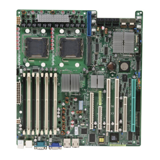
Page 30: Motherboard Layouts
2.2.4 2.2.4 2.2.4 Motherboard layouts Motherboard layouts Motherboard layouts 2.2.4 2.2.4 Motherboard layouts Motherboard layouts DSBF-D/SAS model DSBF-D/SAS model DSBF-D/SAS model DSBF-D/SAS model DSBF-D/SAS model 33cm (13in) KBPWR1 PSUSMB1 ATXPWR1 ATX12V1 PS/2 ATX12V2 T: Mouse USBPW12 B: Keyboard CPU_FAN1 DDR FB-DIMM_31 (64/72 bit, 240-pin module) USB1 DDR FB-DIMM_30 (64/72 bit, 240-pin module) CPU1... - Page 31 DSBF-D/1U model DSBF-D/1U model DSBF-D/1U model DSBF-D/1U model DSBF-D/1U model 33cm (13in) KBPWR1 PSUSMB1 ATXPWR1 ATX12V1 PS/2 ATX12V2 T: Mouse USBPW12 B: Keyboard CPU_FAN1 DDR FB-DIMM_31 (64/72 bit, 240-pin module) USB1 DDR FB-DIMM_30 (64/72 bit, 240-pin module) CPU1 USB2 DDR FB-DIMM_21 (64/72 bit, 240-pin module) DDR FB-DIMM_20 (64/72 bit, 240-pin module) REAR_FAN1 DDR FB-DIMM_11 (64/72 bit, 240-pin module)
- Page 32 DSBF-D model DSBF-D model DSBF-D model DSBF-D model DSBF-D model 33cm (13in) KBPWR1 PSUSMB1 ATXPWR1 ATX12V1 PS/2 ATX12V2 T: Mouse USBPW12 B: Keyboard CPU_FAN1 DDR FB-DIMM_31 (64/72 bit, 240-pin module) USB1 DDR FB-DIMM_30 (64/72 bit, 240-pin module) CPU1 USB2 DDR FB-DIMM_21 (64/72 bit, 240-pin module) DDR FB-DIMM_20 (64/72 bit, 240-pin module) REAR_FAN1 DDR FB-DIMM_11 (64/72 bit, 240-pin module)
-
Page 33: Layout Contents
2.2.5 2.2.5 2.2.5 Layout contents Layout contents Layout contents 2.2.5 2.2.5 Layout contents Layout contents S l o t s / S o c k e t s S l o t s / S o c k e t s S l o t s / S o c k e t s P a g e P a g e... - Page 34 R e a r p a n e l c o n n e c t o r s R e a r p a n e l c o n n e c t o r s R e a r p a n e l c o n n e c t o r s P a g e P a g e P a g e...
-
Page 35: Central Processing Unit (Cpu)
Contact your retailer immediately if the PnP cap is missing, or if you see any damage to the PnP cap/socket contacts/motherboard components. ASUS will shoulder the cost of repair only if the damage is shipment/ transit-related. •... - Page 36 Press the load lever with your thumb (A), then move it to the left (B) until it is released from the retention tab. R e t e n t i o n t a b R e t e n t i o n t a b R e t e n t i o n t a b R e t e n t i o n t a b R e t e n t i o n t a b...
- Page 37 Close the load plate (A), then push the load lever (B) until it snaps into the retention tab. The CPU fits in only one correct orientation. DO NOT force the CPU into the socket to prevent bending the connectors on the socket and damaging the CPU! Notes on Intel Notes on Intel...
-
Page 38: Installing The Cpu Heatsink And Fan
2.3.2 2.3.2 2.3.2 Installing the CPU heatsink and fan Installing the CPU heatsink and fan Installing the CPU heatsink and fan 2.3.2 2.3.2 Installing the CPU heatsink and fan Installing the CPU heatsink and fan The Intel ® Xeon™ processors require an Intel certified heatsink and fan assembly to ensure optimum thermal condition and performance. - Page 39 Use a Phillips screwdriver to tighten the four heatsink screws in a diagonal sequence. Connect the fan cable to the 4-pin connector labeled CPU_FAN1. Do not forget to connect the CPU fan cable! Hardware monitoring errors may occur if you fail to plug this connector. C P U _ F A N 1 C P U _ F A N 1 C P U _ F A N 1...
-
Page 40: System Memory
The figure illustrates the location of the FB-DIMM sockets: 128 Pins 112 Pins DIMM_31 DIMM_30 DIMM_21 DIMM_20 DIMM_11 DIMM_10 DIMM_01 DIMM_00 DSBF-D Series 240-pin FB-DIMM sockets 2.4.2 2.4.2 2.4.2 2.4.2 2.4.2 Memory configurations Memory configurations Memory configurations Memory configurations Memory configurations You may install 256 MB, 512 MB, 1 GB, 2 GB, and 4 GB registered ECC FB-DIMMs into the DIMM sockets. - Page 41 Rank population Rank population Rank population Rank population Rank population M C H M C H M C H M C H M C H C h a n n e l C h a n n e l C h a n n e l C h a n n e l C h a n n e l C h : 1...
-
Page 42: Memory Mirroring And Sparing Technology
2.4.3 2.4.3 2.4.3 Memory mirroring and sparing technology Memory mirroring and sparing technology Memory mirroring and sparing technology 2.4.3 2.4.3 Memory mirroring and sparing technology Memory mirroring and sparing technology The Intel 5000P chipset supports the memory mirroring and sparing technology. - Page 43 2. Configuration 2 (Mirroring) : E i g h t m e m o r i e s p o p u l a t i o n E i g h t m e m o r i e s p o p u l a t i o n E i g h t m e m o r i e s p o p u l a t i o n E i g h t m e m o r i e s p o p u l a t i o n E i g h t m e m o r i e s p o p u l a t i o n...
- Page 44 Number of DIMMs Memory slot/s to use Branch 1 Channel 3 DIMM 31 DIMM 30 Channel 2 DIMM 21 DIMM 20 Branch 0 Channel 1 DIMM 11 V DIMM 10 V (Enable Sparing) Channel 0 DIMM 01 V DIMM 00 V 2.
- Page 45 3. While enabling “Branch 0 Rank Sparing” and “Branch 1 Rank Sparing”: - The system will auto select the largest pair ranks size in the channel 0 or 1 of the Branch 0 and channel 3 or 4 of the Branch 1, and assign as the sparing DIMMs.
-
Page 46: Installing A Dimm
2.4.4 2.4.4 2.4.4 Installing a DIMM Installing a DIMM Installing a DIMM 2.4.4 2.4.4 Installing a DIMM Installing a DIMM Make sure to unplug the power supply before adding or removing DIMMs or other system components. Failure to do so may cause severe damage to both the motherboard and the components. -
Page 47: Installing The Optional Memcool Fb-Dimm Fan
2.4.6 2.4.6 2.4.6 Installing the optional MemCool FB-DIMM fan Installing the optional MemCool FB-DIMM fan Installing the optional MemCool FB-DIMM fan 2.4.6 2.4.6 Installing the optional MemCool FB-DIMM fan Installing the optional MemCool FB-DIMM fan The FB-DIMMs generate heat during continued operation. To ensure optimum thermal condition and performance, install the optional MemCool FB-DIMM fan. - Page 48 Position top cover over the fan base. Insert the top cover legs into the slot on the fan base legs. Push down carefully until the legs are securely in place and the top cover hooks snap in place. Make sure the cables pass through the notch on the fan base as shown.
-
Page 49: Uninstalling The Optional Memcool Fb-Dimm Fan
2.4.7 2.4.7 2.4.7 Uninstalling the optional MemCool FB-DIMM fan nstalling the optional MemCool FB-DIMM fan nstalling the optional MemCool FB-DIMM fan nstalling the optional MemCool FB-DIMM fan 2.4.7 2.4.7 nstalling the optional MemCool FB-DIMM fan Unplug the fan cable. Grip the top cover clamps until the top cover hooks are released, then carefully lift the top cover while supporting the... -
Page 50: Expansion Slots
Expansion slots In the future, you may need to install expansion cards. The following sub-sections describe the slots and the expansion cards that they support. Make sure to unplug the power cord before adding or removing expansion cards. Failure to do so may cause you physical injury and damage motherboard components. -
Page 51: Interrupt Assignments
2.5.3 2.5.3 2.5.3 Interrupt assignments Interrupt assignments Interrupt assignments 2.5.3 2.5.3 Interrupt assignments Interrupt assignments Standard interrupt assignments Standard interrupt assignments Standard interrupt assignments Standard interrupt assignments Standard interrupt assignments I R Q I R Q I R Q I R Q I R Q P r i o r i t y P r i o r i t y... -
Page 52: Pci/Pci-X Slots
The DDR2 SO-DIMM socket on the motherboard supports an ASUS ® Server Management Board 3 Series. D D R 2 S O - D I M M s o c k e t D D R 2 S O - D I M M s o c k e t... -
Page 53: Pci Express X16 Slot (X8 Link)
2.5.6 2.5.6 2.5.6 PCI Express x8 slot PCI Express x8 slot PCI Express x8 slot 2.5.6 2.5.6 PCI Express x8 slot PCI Express x8 slot The onboard PCI Express x8 slot provides x8 link to the MCH. This slot is designed for various server class high performance add-on cards like SCSI RAID card, fiber-channel card, etc. -
Page 54: Jumpers
Removing the cap will cause system boot failure! CLRTC1 Normal Clear CMOS DSBF-D Series Clear RTC RAM (Default) 2 - 3 0 2 - 3 0 C h a p t e r 2 : H a r d w a r e i n f o r m a t i o n... - Page 55 +5VSB (Default) USBPW34 +5VSB (Default) DSBF-D Series USB device wake up • The USB device wake-up feature requires a power supply that can provide 500mA on the +5VSB lead for each USB port; otherwise, the system will not power up.
- Page 56 +5VSB (Default) DSBF-D Series Keyboard power setting 5 . 5 . V G A c o n t r o l l e r s e t t i n g ( 3 - p i n V G A _ E N 1 )
- Page 57 MSM) (Default) DSBF-D Series ESB2E SATA port S/W RAID setting A S U S D S B F - D S e r i e s A S U S D S B F - D S e r i e s...
- Page 58 Normal BIOS Recovery (Default) DSBF-D Series BIOS recovery setting 2 - 3 4 2 - 3 4 C h a p t e r 2 : H a r d w a r e i n f o r m a t i o n...
-
Page 59: Switch
SW5_FRNT_FAN3 SW6_FRNT_FAN4 SW7_REAR_FAN1 SW8_REAR_FAN2 DSBF-D Series DIP switches The following table shows the corresponding switch for each fan connector. S w i t c h S w i t c h F a n c o n n e c t o r... -
Page 60: Connectors
Connectors 2.8.1 2.8.1 2.8.1 2.8.1 2.8.1 Rear panel connectors Rear panel connectors Rear panel connectors Rear panel connectors Rear panel connectors 1 . 1 . P S / 2 m o u s e p o r t ( g r e e n ) . P S / 2 m o u s e p o r t ( g r e e n ) . -
Page 61: Internal Connectors
NOTE: Orient the red markings on the floppy ribbon cable to PIN 1. DSBF-D Series Floppy disk drive connector 2 . 2 . I D E c o n n e c t o r ( 4 0 - 1 p i n P R I _ I D E ) - Page 62 This connector is used to connect to a hard disk drive active LED connector on the SCSI or RAID card. HDLED1 DSBF-D Series storage card activity LED connector 2 - 3 8 2 - 3 8 C h a p t e r 2 : H a r d w a r e i n f o r m a t i o n...
- Page 63 Serial Attached SCSI and Serial ATA. Each connector supports up to four (4) devices. DSBF-D Series MINI SAS connectors To connect the mini-SAS cable: Plug in the mini-SAS cable to the mini-SAS connector until the cable lock snaps in place.
- Page 64 COM2 PIN 1 DSBF-D Series Serial port connectors The serial port module is purchased separately. 2 - 4 0 2 - 4 0...
- Page 65 SMBus function. PSUSMB1 DSBF-D Series Power supply SMBus connector A S U S D S B F - D S e r i e s A S U S D S B F - D S e r i e s...
- Page 66 24-pin Power Connector ATX12V1 8-pin ATX12V2 4-pin DSBF-D Series ATX power connectors +12V DC +12V DC 2 - 4 2 2 - 4 2 C h a p t e r 2 : H a r d w a r e i n f o r m a t i o n...
- Page 67 This connector is for a parallel port. Connect the parallel port module cable to this connector, then install the module to a slot opening at the back of the system chassis. Pin 1 LPT1 DSBF-D Series Parallel port connector 1 2 . 1 2 . 1 2 . 1 2 .
- Page 68 ( D S B F - D / S A S m o d e l o n l y ) This connector is for the front panel LED port indicator that shows the SAS HDD status. SASLED1 DSBF-D Series SASLED connector 1 4 . 1 4 . 1 4 .
- Page 69 The system panel connector is color-coded for easy connection. PANEL1 DSBF-D Series System panel connector • S y s t e m p o w e r L E D ( G r e e n 3 - p i n P L E D )
- Page 70 SMB, locator LED and switch, chassis intrusion, and LAN LEDs. AUX_PANEL1 PIN1 DSBF-D Series Auxiliary panel connector 1 . 1 . F r o n t P a n e l S M B u s ( 6 - 1 p i n )
- Page 71 This chapter describes the power up sequence, and ways of shutting down the system. Powering up...
- Page 72 Chapter summary Starting up for the first time ..........3-1 Turning off the computer ............. 3-2 A S U S D S B F - D S e r i e s A S U S D S B F - D S e r i e s A S U S D S B F - D S e r i e s A S U S D S B F - D S e r i e s A S U S D S B F - D S e r i e s...
-
Page 73: Starting Up For The First Time
Starting up for the first time After making all the connections, replace the system case cover. Be sure that all switches are off. Connect the power cord to the power connector at the back of the system chassis. Connect the power cord to a power outlet that is equipped with a surge protector. -
Page 74: Turning Off The Computer
Turning off the computer 3.2.1 3.2.1 3.2.1 3.2.1 3.2.1 Using the OS shut down function Using the OS shut down function Using the OS shut down function Using the OS shut down function Using the OS shut down function If you are using Windows ®... -
Page 75: Chapter 4: Bios Setup
This chapter tells how to change the system settings through the BIOS Setup menus. Detailed descriptions of the BIOS parameters are also provided. BIOS setup... - Page 76 Chapter summary Managing and updating your BIOS ........4-1 BIOS setup program ............. 4-8 Main menu ................4-12 Advanced menu ..............4-17 Server menu ............... 4-30 Security menu ..............4-32 Boot menu ................4-34 Exit menu ................4-36 A S U S D S B F - D S e r i e s A S U S D S B F - D S e r i e s A S U S D S B F - D S e r i e s A S U S D S B F - D S e r i e s...
-
Page 77: Managing And Updating Your Bios
Save a copy of the original motherboard BIOS file to a bootable floppy disk in case you need to restore the BIOS in the future. Copy the original motherboard BIOS using the ASUS Update or AwardBIOS Flash utilities. 4.1.1 4.1.1 4.1.1... -
Page 78: Updating The Bios Using The Phoenix Phlash16 Utility
Phlash16 Utility. Follow these instructions to update the BIOS using this utility. Download the latest BIOS file from the ASUS web site. Save the file to a floppy disk. Make sure you copy the correct BIOS file for the specific model of your motherboard. -
Page 79: Asus Crashfree Bios 2 Utility
ASUS CrashFree BIOS 2 utility ASUS CrashFree BIOS 2 utility The ASUS CrashFree BIOS 2 is an auto recovery tool that allows you to restore the BIOS file when it fails or gets corrupted during the updating process. You can update a corrupted BIOS file using the motherboard support CD and a floppy disk. - Page 80 Phoenix Phlash16 Utility Version 1.6.1.9 Copyright (c) Phoenix Technologies Ltd., 2005 Performing the following function Load Image File BIOS.WPH Verify interface information Backup system BIOS ROM Check flash memory type(s) Flash memory block: Save block Restore block Zero out block Erase block Program block Verify block...
-
Page 81: Asus Update Utility
ASUS Update utility 4.1.4 4.1.4 ASUS Update utility ASUS Update utility The ASUS Update is a utility that allows you to manage, save, and update the motherboard BIOS in Windows ® environment. The ASUS Update utility allows you to: • Save the current BIOS file •... - Page 82 Updating the BIOS through the Internet Updating the BIOS through the Internet Updating the BIOS through the Internet To update the BIOS through the Internet: Launch the ASUS Update utility from the Windows ® desktop by clicking S t a r t S t a r t S t a r t >...
- Page 83 A S U S U p d a t e A S U S U p d a t e A S U S U p d a t e. The ASUS Update main window appears. A S U S U p d a t e...
-
Page 84: Bios Setup Program
The BIOS setup screens shown in this section are for reference purposes only, and may not exactly match what you see on your screen. • Visit the ASUS website (www.asus.com) to download the latest BIOS file for this motherboard. 4 - 8 4 - 8... -
Page 85: Bios Menu Screen
4.2.1 4.2.1 4.2.1 BIOS menu screen BIOS menu screen BIOS menu screen 4.2.1 4.2.1 BIOS menu screen BIOS menu screen M e n u i t e m s M e n u i t e m s M e n u i t e m s M e n u i t e m s M e n u i t e m s M e n u b a r... -
Page 86: Legend Bar
4.2.3 4.2.3 4.2.3 Legend bar Legend bar Legend bar 4.2.3 4.2.3 Legend bar Legend bar At the bottom of the Setup screen is a legend bar. The keys in the legend bar allow you to navigate through the various setup menus. The following table lists the keys found in the legend bar with their corresponding functions. -
Page 87: Pop-Up Window
4.2.7 4.2.7 4.2.7 Pop-up window Pop-up window Pop-up window 4.2.7 4.2.7 Pop-up window Pop-up window Select a menu item then press <Enter> to display a pop-up window with the configuration options for that item. PhoenixBIOS Setup Utility Main Advanced Server Security Boot Exit... -
Page 88: Main Menu
Main menu When you enter the BIOS Setup program, the Main menu screen appears, giving you an overview of the basic system information. Refer to section “5.2.1 BIOS menu screen” for information on the menu screen items and how to navigate through them. PhoenixBIOS Setup Utility Main Advanced... -
Page 89: Ide Configuration
4.3.4 4.3.4 4.3.4 IDE Configuration IDE Configuration IDE Configuration 4.3.4 4.3.4 IDE Configuration IDE Configuration PhoenixBIOS Setup Utility Main IDE Configuration Item Specific Help Fixed disk boot sector: [Normal] Write protects boot sector on hard disk to S-ATA Configuration protect against viruses. ↑... - Page 90 Serial ATA [Enabled] Serial ATA [Enabled] Serial ATA [Enabled] Serial ATA [Enabled] Serial ATA [Enabled] Allows you to enable or disable the Serial ATA function. Configuration options: [Disabled] [Enabled] SATA Controller Mode Option [Enhanced] Allows selection of the Serial ATA operation mode depending on the operating system (OS) that you installed.
-
Page 91: Ide Channel 0 Master/Slave; Sata Port 1/2/3/4
4.3.5 4.3.5 4.3.5 IDE Channel 0 Master/Slave; IDE Channel 0 Master/Slave; IDE Channel 0 Master/Slave; 4.3.5 4.3.5 IDE Channel 0 Master/Slave; IDE Channel 0 Master/Slave; SATA Port 1/2/3/4 SATA Port 1/2/3/4 SATA Port 1/2/3/4 SATA Port 1/2/3/4 SATA Port 1/2/3/4 PhoenixBIOS Setup Utility Main IDE Channel 0 Master... -
Page 92: System Information
This menu gives you an overview of the general system specifications. The BIOS automatically detects the items in this menu. PhoenixBIOS Setup Utility Main System Information Item Specific Help Model Name ASUS DSBF-D/SAS The detailed information Model ID 8012A0 for CPUs ASUS BIOS Version 1000.021... -
Page 93: Advanced Menu
Advanced menu The Advanced menu items allow you to change the settings for the CPU and other system devices. Take caution when changing the settings of the Advanced menu items. Incorrect field values can cause the system to malfunction. PhoenixBIOS Setup Utility Main Advanced Server... - Page 94 Multiprocessor Specification [1.4] Multiprocessor Specification [1.4] Multiprocessor Specification [1.4] Multiprocessor Specification [1.4] Multiprocessor Specification [1.4] Allows you to configure the MP Specification revision level. Configuration options: [1.1] [1.4] Frequency Ratio [Default] Frequency Ratio [Default] Frequency Ratio [Default] Frequency Ratio [Default] Frequency Ratio [Default] Allows you to select the processor frequency ratio.
-
Page 95: Chipset Configuration
Echo TPR [Disabled] Echo TPR [Disabled] Echo TPR [Disabled] Echo TPR [Disabled] Echo TPR [Disabled] Configuration options: [Disabled] [Enabled] Discrete MTRR Allocation [Disabled] Discrete MTRR Allocation [Disabled] Discrete MTRR Allocation [Disabled] Discrete MTRR Allocation [Disabled] Discrete MTRR Allocation [Disabled] Configuration options: [Disabled] [Enabled] 4.4.2 4.4.2 4.4.2... - Page 96 Branch 0 Rank Sparing [Disabled] Branch 0 Rank Sparing [Disabled] Branch 0 Rank Sparing [Disabled] Branch 0 Rank Sparing [Disabled] Branch 0 Rank Sparing [Disabled] Allows you to enable or disable the Branch 0 rank/DIMM Sparing feature. Configuration options: [Disabled] [Enabled] Branch 1 Rank Sparing [Disabled] Branch 1 Rank Sparing [Disabled] Branch 1 Rank Sparing [Disabled]...
- Page 97 Memory Cache Memory Cache Memory Cache Memory Cache Memory Cache PhoenixBIOS Setup Utility Advanced Chipset Configuration Item Specific Help Cache System BIOS area [Write Protect] Controls caching of the Cache Video BIOS area [Write Protect] system BIOS area. Cache Base 0-512k [Write Back] Cache Base 512k-640k [Write Back]...
-
Page 98: Pci Configuration
Cache A000 - AFFF / Cache B000 - BFFF / Cache C800 - CBFF / Cache CC00 - CFFF / Cache D000 - D3FF / Cache D400 - D7FF / Cache D800 - DBFF / Cache DC00 - DFFF / Cache E000 - E3FF / Cache E400 - E7FF / Cache E800 - EBFF/ Cache EC00 - EFFF Refer to the configuration options information below: Disabled - This block is not cached. -
Page 99: Ich Usb Control Sub-Menu
Palette Snooping [Disabled] Palette Snooping [Disabled] Palette Snooping [Disabled] Palette Snooping [Disabled] Palette Snooping [Disabled] When set to [Enabled], the palette snooping feature informs the PCI devices that an ISA graphics device is installed in the system so that the latter can function correctly. -
Page 100: Peripheral Devices Configuration
Legacy USB Support [Enabled] Legacy USB Support [Enabled] Legacy USB Support [Enabled] Legacy USB Support [Enabled] Legacy USB Support [Enabled] Allows you to enable or disable support for USB devices on legacy operating systems (OS). Setting to [Enabled] allows the system to detect the presence of USB devices at startup. - Page 101 Mode [Normal] Mode [Normal] Mode [Normal] Mode [Normal] Mode [Normal] Allows you to set the mode for serial port B. Configuration options: [Normal] [IR] [ASK-IR] Base I/O address [2F8] Base I/O address [2F8] Base I/O address [2F8] Base I/O address [2F8] Base I/O address [2F8] Allows you to select the base I/O address for serial port B.
-
Page 102: Acpi Configuration
4.4.6 4.4.6 4.4.6 4.4.6 4.4.6 ACPI Configuration ACPI Configuration ACPI Configuration ACPI Configuration ACPI Configuration This menu shows the Advanced Configuration and Power Interface (ACPI) configuration settings. Select an item then press <Enter> to display the configuration options. PhoenixBIOS Setup Utility Advanced ACPI Configuration Item Specific Help... -
Page 103: Power On Configuration
4.4.7 4.4.7 4.4.7 4.4.7 4.4.7 Power On Configuration Power On Configuration Power On Configuration Power On Configuration Power On Configuration This menu shows the power configuration settings. Select an item then press <Enter> to display the configuration options. PhoenixBIOS Setup Utility Advanced Power On Configuration Item Specific Help... -
Page 104: Hardware Monitor
Power On By RTC Alarm [Disabled] Power On By RTC Alarm [Disabled] Power On By RTC Alarm [Disabled] Power On By RTC Alarm [Disabled] Power On By RTC Alarm [Disabled] Allows you to enable or disable RTC to generate a wake-up event. Configuration options: [Disabled] [Enabled] The following items appear only if you enable the P o w e r O n B y R T C P o w e r O n B y R T C... - Page 105 Scroll down to display more items: PhoenixBIOS Setup Utility Advanced Hardware Monitor Item Specific Help CPU1 Domain 0 Target Temperature [075] When the current CPU1 Domain 1 Target Temperature [060] temperature equals this CPU2 Domain 0 Target Temperature [075] limit, the fan will be CPU2 Domain 1 Target Temperature [060] turned on IF it is not SYSTEM1 Target Temperature...
-
Page 106: Console Redirection
Server menu This Server menu items allow you to customize the server features. PhoenixBIOS Setup Utility Main Advanced Server Security Boot Exit Console Redirection Item Specific Help DMI Event Logging Additional setup menus to configure console. ↑ ↑ ↑ ↑ ↑ ↓ ↓ ↓ ↓ ↓ : Select Item F1:Help -/+: Change Values F9: Setup Defaults... - Page 107 The following items appear only if you set the C o m P o r t A d d r e s s C o m P o r t A d d r e s s C o m P o r t A d d r e s s C o m P o r t A d d r e s s C o m P o r t A d d r e s s item to [On-board COM A] or [On-board COM B].
- Page 108 DMI Event Logging DMI Event Logging DMI Event Logging DMI Event Logging DMI Event Logging PhoenixBIOS Setup Utility Main Advanced Server Security Boot Exit DMI Event Logging Item Specific Help Press Enter to mark all Event log validity Valid DMI events in the event Event log capacity Space Available log as read.
-
Page 109: Security Menu
Security menu PhoenixBIOS Setup Utility Main Advanced Server Security Boot Exit Supervisor Password Is Clear Item Specific Help User Password Is Clear Supervisor Password Set Supervisor Password [Enter] controls access to the Set User Password [Enter] setup utility. Password Check [Setup] Password Lock Mode [Disabled]... - Page 110 In the E n t e r c u r r e n t p a s s w o r d E n t e r c u r r e n t p a s s w o r d E n t e r c u r r e n t p a s s w o r d E n t e r c u r r e n t p a s s w o r d E n t e r c u r r e n t p a s s w o r d field, type in your current...
-
Page 111: Boot Menu
Boot menu PhoenixBIOS Setup Utility Main Advanced Server Security Boot Exit Boot Device Priority Item Specific Help Boot Features Specify the boot priority sequence of all boot devices. ↑ ↑ ↑ ↑ ↑ ↓ ↓ ↓ ↓ ↓ : Select Item F1:Help -/+: Change Values F9: Setup Defaults... -
Page 112: Boot Features
Full Logo Display [Enabled] Allows you to enable or disable the full screen logo display feature. Configuration options: [Disabled] [Enabled] Set this item to [Enabled] to use the ASUS MyLogo2™ feature. Bootup Num-Lock [On] Bootup Num-Lock [On] Bootup Num-Lock [On]... -
Page 113: Exit Menu
SETUP prompt [Enabled] SETUP prompt [Enabled] SETUP prompt [Enabled] SETUP prompt [Enabled] SETUP prompt [Enabled] When this item is set to Enabled, the system displays the message “Press DEL to run Setup” during POST. Configuration options: [Disabled] [Enabled] Interrupt 19 Capture [Enabled] Interrupt 19 Capture [Enabled] Interrupt 19 Capture [Enabled] Interrupt 19 Capture [Enabled]... - Page 114 Discard Changes Discard Changes Discard Changes Discard Changes Discard Changes Select this option to discard the changes that you made, and restore the previously saved values. When a confirmation window appears: • select [Yes], then press <Enter> to discard any changes and load the previously saved values.
- Page 115 This chapter provides instructions for setting up, creating, and configuring RAID sets using the available utilities. R AID configuration...
- Page 116 Chapter summary Setting up RAID ..............5-1 LSI Logic Embedded SATA RAID Setup Utility ...... 5-4 Intel ® Matrix Storage Manager Option ROM Utility ....5-31 Global Array Manager ............5-39 LSI Logic MPT Setup Utility (DSBF-D/SAS model only) ..........5-40 A S U S D S B F - D S e r i e s A S U S D S B F - D S e r i e s A S U S D S B F - D S e r i e s...
-
Page 117: Setting Up Raid
Setting up RAID The motherboard comes with the following RAID solutions: DSBF-D/1U and DSBF-D models DSBF-D/1U and DSBF-D models DSBF-D/1U and DSBF-D models DSBF-D/1U and DSBF-D models DSBF-D/1U and DSBF-D models • LSI Logic Embedded SATA RAID LSI Logic Embedded SATA RAID LSI Logic Embedded SATA RAID LSI Logic Embedded SATA RAID and the I n t e l I n t e l... -
Page 118: Installing Hard Disk Drives
If you want to boot the system from a hard disk drive included in a created RAID set, copy first the RAID driver from the support CD to a floppy disk before you install an operating system to the selected hard disk drive. -
Page 119: Setting The Raid Item In Bios
5.1.3 5.1.3 5.1.3 Setting the RAID item in BIOS Setting the RAID item in BIOS Setting the RAID item in BIOS 5.1.3 5.1.3 Setting the RAID item in BIOS Setting the RAID item in BIOS You must set the RAID item in the BIOS Setup before you can create a RAID set from SATA hard disk drives attached to the SATA connectors supported by the Intel ®... -
Page 120: Lsi Logic Embedded Sata Raid Setup Utility
LSI Logic Embedded SATA RAID Setup Utility The LSI Logic Embedded SATA RAID Setup Utility allows you to create RAID 0, RAID 1, or RAID 10 set(s) from SATA hard disk drives connected to the SATA connectors supported by the motherboard Southbridge chip. To enter the LSI Logic Embedded SATA RAID Setup Utility: Turn on the system after installing all the SATA hard disk drives. -
Page 121: Creating A Raid 0 Or Raid 1 Set
M e n u M e n u M e n u M e n u M e n u D e s c r i p t i o n D e s c r i p t i o n D e s c r i p t i o n D e s c r i p t i o n D e s c r i p t i o n... - Page 122 The A R R A Y S E L E C T I O N M E N U A R R A Y S E L E C T I O N M E N U A R R A Y S E L E C T I O N M E N U A R R A Y S E L E C T I O N M E N U displays the available drives A R R A Y S E L E C T I O N M E N U connected to the SATA ports.
- Page 123 Press <F10>, select the configurable array, then press <SpaceBar>. The logical drive information appears including a Logical Drive menu that allows you to change the logical drive parameters. A S U S D S B F - D S e r i e s A S U S D S B F - D S e r i e s 5 - 7 5 - 7...
- Page 124 Select R A I D R A I D R A I D R A I D from the L o g i c a l D r i v e L o g i c a l D r i v e L o g i c a l D r i v e menu, then press <Enter>.
- Page 125 10. When finished setting the selected logical drive configuration, select A c c e p t A c c e p t from the menu, then press <Enter>. A c c e p t A c c e p t A c c e p t 11.
- Page 126 Using New Configuration Using New Configuration Using New Configuration Using New Configuration Using New Configuration When a RAID set is already existing, using the N e w C o n f i g u r a t i o n N e w C o n f i g u r a t i o n N e w C o n f i g u r a t i o n N e w C o n f i g u r a t i o n...
-
Page 127: Creating A Raid 10 Set
5.2.2 5.2.2 5.2.2 Creating a RAID 10 set Creating a RAID 10 set Creating a RAID 10 set 5.2.2 5.2.2 Creating a RAID 10 set Creating a RAID 10 set You can create a RAID 10 set using four identical hard disk drives. E a s y C o n f i g u r a t i o n E a s y C o n f i g u r a t i o n To create a RAID 10 set using the E a s y C o n f i g u r a t i o n... - Page 128 Select all the drives required for the RAID 10 set, then press <Enter>. The configurable array appears on screen. Press <F10>, select the configurable array, then press <SpaceBar>. The logical drive information appears including a Logical Drive menu that allows you to change the logical drive parameters. 5 - 1 2 5 - 1 2 C h a p t e r 5 : R A I D c o n f i g u r a t i o n...
- Page 129 Select R A I D R A I D R A I D R A I D from the L o g i c a l D r i v e L o g i c a l D r i v e L o g i c a l D r i v e L o g i c a l D r i v e menu, then press <Enter>.
- Page 130 10. When finished setting the selected logical drive configuration, select A c c e p t A c c e p t from the menu, then press <Enter>. A c c e p t A c c e p t A c c e p t 11.
-
Page 131: Adding Or Viewing A Raid Configuration
5.2.3 5.2.3 5.2.3 Adding or viewing a RAID configuration Adding or viewing a RAID configuration Adding or viewing a RAID configuration 5.2.3 5.2.3 Adding or viewing a RAID configuration Adding or viewing a RAID configuration You can add a new RAID configuration or view an existing configuration V i e w / A d d C o n f i g u r a t i o n V i e w / A d d C o n f i g u r a t i o n using the V i e w / A d d C o n f i g u r a t i o n... - Page 132 Select all the drives required for the RAID set, then press <Enter>. The configurable array appears on screen. Press <F10>, select the configurable array, then press <SpaceBar>. The logical drive information appears including a Logical Drive menu that allows you to change the logical drive parameters. 5 - 1 6 5 - 1 6 C h a p t e r 5 : R A I D c o n f i g u r a t i o n...
- Page 133 Follow steps 6 to 7 of the C r e a t i n g a R A I D s e t : U s i n g E a s y C r e a t i n g a R A I D s e t : U s i n g E a s y C r e a t i n g a R A I D s e t : U s i n g E a s y C r e a t i n g a R A I D s e t : U s i n g E a s y C r e a t i n g a R A I D s e t : U s i n g E a s y...
-
Page 134: Initializing The Logical Drives
5.2.4 5.2.4 5.2.4 Initializing the logical drives Initializing the logical drives Initializing the logical drives 5.2.4 5.2.4 Initializing the logical drives Initializing the logical drives After creating the RAID set(s), you must initialize the logical drives. You I n i t i a l i z e I n i t i a l i z e may initialize the logical drives of a RAID set(s) using the I n i t i a l i z e I n i t i a l i z e... - Page 135 When prompted, press the <SpaceBar> to select Y e s Y e s Y e s Y e s from the Y e s I n i t i a l i z e ? I n i t i a l i z e ? dialog box, then press <Enter>. You may also press I n i t i a l i z e ? I n i t i a l i z e ? I n i t i a l i z e ?
- Page 136 When initialization is completed, press <Esc>. Using the Objects command Using the Objects command Using the Objects command Using the Objects command Using the Objects command O b j e c t s O b j e c t s To initialize the logical drives using the O b j e c t s O b j e c t s O b j e c t s command:...
- Page 137 Select L o g i c a l D r i v e L o g i c a l D r i v e L o g i c a l D r i v e L o g i c a l D r i v e from the O b j e c t s O b j e c t s O b j e c t s sub-menu, then press O b j e c t s...
- Page 138 When prompted, press the <SpaceBar> to select Y e s Y e s Y e s Y e s from the Y e s I n i t i a l i z e ? I n i t i a l i z e ? dialog box, then press <Enter>. You may also press I n i t i a l i z e ? I n i t i a l i z e ? I n i t i a l i z e ?
-
Page 139: Rebuilding Failed Drives
5.2.5 5.2.5 5.2.5 Rebuilding failed drives Rebuilding failed drives Rebuilding failed drives 5.2.5 5.2.5 Rebuilding failed drives Rebuilding failed drives You can manually rebuild failed hard disk drives using the R e b u i l d R e b u i l d R e b u i l d R e b u i l d R e b u i l d... - Page 140 After selecting the drive to rebuild, press <F10>. The indicator for the selected drive now shows R B L D R B L D R B L D. R B L D R B L D When prompted, press <Y> to to rebuild the drive. When rebuild is complete, press any key to continue.
-
Page 141: Checking The Drives For Data Consistency
5.2.6 5.2.6 5.2.6 Checking the drives for data consistency Checking the drives for data consistency Checking the drives for data consistency 5.2.6 5.2.6 Checking the drives for data consistency Checking the drives for data consistency You can check and verify the accuracy of data redundancy in the selected logical drive. - Page 142 When prompted, press the <SpaceBar> to select Y e s Y e s Y e s Y e s from the Y e s C o n s i s t e n c y C h e c k C o n s i s t e n c y C h e c k dialog box, then press <Enter>.
- Page 143 Using the Objects command Using the Objects command Using the Objects command Using the Objects command Using the Objects command O b j e c t s O b j e c t s To check data consistency using the O b j e c t s O b j e c t s O b j e c t s command: From the Management Menu, select O b j e c t s...
-
Page 144: Deleting A Raid Configuration
5.2.7 5.2.7 5.2.7 Deleting a RAID configuration Deleting a RAID configuration Deleting a RAID configuration 5.2.7 5.2.7 Deleting a RAID configuration Deleting a RAID configuration To delete a RAID configuration: C o n f i g u r e C o n f i g u r e C l e a r C l e a r From the Management Menu, select C o n f i g u r e... -
Page 145: Selecting The Boot Drive From A Raid Set
5.2.8 5.2.8 5.2.8 Selecting the boot drive from a RAID set Selecting the boot drive from a RAID set Selecting the boot drive from a RAID set 5.2.8 5.2.8 Selecting the boot drive from a RAID set Selecting the boot drive from a RAID set You must have created a new RAID configuration before you can select the C r e a t i n g a R A I D s e t : U s i n g C r e a t i n g a R A I D s e t : U s i n g... -
Page 146: Enabling The Writecache
5.2.9 5.2.9 5.2.9 Enabling the WriteCache Enabling the WriteCache Enabling the WriteCache 5.2.9 5.2.9 Enabling the WriteCache Enabling the WriteCache You may enable the RAID controller’s W r i t e C a c h e W r i t e C a c h e W r i t e C a c h e W r i t e C a c h e option to improve the W r i t e C a c h e... -
Page 147: Intel
® Intel Matrix Storage Manager Option ROM Utility The Intel ® Matrix Storage Manager Option ROM utility allows you to create RAID 0, RAID 1, RAID 0+1, and RAID 5 set(s) from Serial ATA hard disk drives. To enter the Intel ®... -
Page 148: Creating A Raid 0 Set (Stripe)
5.3.1 5.3.1 5.3.1 Creating a RAID 0 set (Stripe) Creating a RAID 0 set (Stripe) Creating a RAID 0 set (Stripe) 5.3.1 5.3.1 Creating a RAID 0 set (Stripe) Creating a RAID 0 set (Stripe) To create a RAID 0 set: 1 . - Page 149 Use the up/down arrow key to select the stripe size for the RAID 0 array, then press <Enter>. The available stripe size values range from 4 KB to 128 KB. The default stripe size is 128 KB. A lower stripe size is recommended for server systems. A higher stripe size is recommended for multimedia computer systems used mainly for audio and video editing.
-
Page 150: Creating A Raid 1 Set (Mirror)
5.3.2 5.3.2 5.3.2 Creating a RAID 1 set (Mirror) Creating a RAID 1 set (Mirror) Creating a RAID 1 set (Mirror) 5.3.2 5.3.2 Creating a RAID 1 set (Mirror) Creating a RAID 1 set (Mirror) To create a RAID 1 set: 1 . -
Page 151: Creating A Raid 10 Set (Stripe + Mirror)
5.3.3 5.3.3 5.3.3 Creating a RAID 10 set (Stripe + Mirror) Creating a RAID 10 set (Stripe + Mirror) Creating a RAID 10 set (Stripe + Mirror) 5.3.3 5.3.3 Creating a RAID 10 set (Stripe + Mirror) Creating a RAID 10 set (Stripe + Mirror) To create a RAID 10 set: 1 . -
Page 152: Creating A Raid 5 Set (Parity)
5.3.4 5.3.4 5.3.4 Creating a RAID 5 set (Parity) Creating a RAID 5 set (Parity) Creating a RAID 5 set (Parity) 5.3.4 5.3.4 Creating a RAID 5 set (Parity) Creating a RAID 5 set (Parity) To create a RAID 5 set: 1 . -
Page 153: Deleting A Raid Set
5.3.5 5.3.5 5.3.5 Deleting a RAID set Deleting a RAID set Deleting a RAID set 5.3.5 5.3.5 Deleting a RAID set Deleting a RAID set Take caution when deleting a RAID set. You will lose all data on the hard disk drives when you delete a RAID set. -
Page 154: Resetting Disks To Non-Raid
5.3.6 5.3.6 5.3.6 Resetting disks to Non-RAID Resetting disks to Non-RAID Resetting disks to Non-RAID 5.3.6 5.3.6 Resetting disks to Non-RAID Resetting disks to Non-RAID Take caution before you reset a RAID volume hard disk drive to non-RAID. Resetting a RAID volume hard disk drive deletes all internal RAID structure on the drive. -
Page 155: Global Array Manager
Global Array Manager You may also create a RAID set(s) in Windows ® operating environment using the Global Array Manager (GAM) application. The GAM application is available from the motherboard support CD. Refer to the GAM user guide in the motherboard support CD for details. A S U S D S B F - D S e r i e s A S U S D S B F - D S e r i e s 5 - 3 9... -
Page 156: Lsi Logic Mpt Setup Utility (Dsbf-D/Sas Model Only)
LSI Logic MPT Setup Utility (DSBF-D/SAS model only) The LSI Logic MPT Setup Utility is an integrated RAID solution that allows you to allows you to create the following RAID set(s) from SAS hard disk drives supported by the LSI1068 PCI-X SAS controller: •... - Page 157 The Adapter Properties screen appears. Use the arrow keys to select R A I D P r o p e r t i e s R A I D P r o p e r t i e s R A I D P r o p e r t i e s R A I D P r o p e r t i e s, then press <Enter>.
- Page 158 The Create New Array screen shows the disks you can add to make up the IM volume. Use the arrow key to select a disk, then move the cursor to the RAID Disk column. To include this disk in the array, press <+>, <->, or <Space>.
- Page 159 Repeat steps 5 and 6 to add the second disk to the volume. When done, press <C> to create the array, then select S a v e S a v e S a v e S a v e S a v e c h a n g e s t h e n e x i t t h i s m e n u c h a n g e s t h e n e x i t t h i s m e n u.
- Page 160 To create an IME volume: The Adapter Properties screen appears. R A I D P r o p e r t i e s R A I D P r o p e r t i e s Use the arrow keys to select R A I D P r o p e r t i e s R A I D P r o p e r t i e s R A I D P r o p e r t i e s, then press <Enter>.
- Page 161 By default, the R A I D D i s k R A I D D i s k R A I D D i s k R A I D D i s k field shows N o N o before array creation. This R A I D D i s k field is grayed out under the following conditions: •...
-
Page 162: Integrated Striping (Is) Volume
5.5.2 5.5.2 5.5.2 Integrated Striping (IS) volume Integrated Striping (IS) volume Integrated Striping (IS) volume 5.5.2 5.5.2 Integrated Striping (IS) volume Integrated Striping (IS) volume Overview Overview Overview Overview Overview The Integrated Striping (IS) feature provides RAID 0 functionality, supporting volumes with two to eight disks. You may combine an IS volume with an IM or IME volume. - Page 163 The Select New Array Type screen apprears. Use the arrow keys to select C r e a t e I M V o l u m e C r e a t e I M V o l u m e C r e a t e I M V o l u m e C r e a t e I M V o l u m e, then press C r e a t e I M V o l u m e...
- Page 164 By default, the R A I D D i s k R A I D D i s k R A I D D i s k R A I D D i s k R A I D D i s k field shows N o N o before array creation.
-
Page 165: Managing Arrays
5.5.3 5.5.3 5.5.3 Managing Arrays Managing Arrays Managing Arrays 5.5.3 5.5.3 Managing Arrays Managing Arrays The LSI Logic MPT Setup Utility allows you to perform other tasks related to configuring and maintaining IM and IME volumes. Refer to this section to view volume properties, manage the hot spare disk, synchronize the array, activate the array, and delete the array. - Page 166 TheView Array screen appears. Here you can view properties of the RAID array(s) created. If you have configured a hot spare, it will also be listed. if you created more than one array, you may view the next array by pressing <Alt+N>. 5 - 5 0 5 - 5 0 C h a p t e r 5 : R A I D c o n f i g u r a t i o n...
- Page 167 Managing hot spares Managing hot spares Managing hot spares Managing hot spares Managing hot spares You may configure one disk as a global hot spare to protect critical data on the IM/IME volume(s). You may create the hot spare disk at the same time you create the IM/IME volume.
- Page 168 Use the arrow key to select the disk you would like to configure as hot spare, then move the cursor to the Hot Spr column. Press <+>, <->, or <Space>. The Drive Status column field now shows Hot Spare. Press <C> to commit the changes. Synchronizing the array Synchronizing the array Synchronizing the array...
- Page 169 Activating an array Activating an array Activating an array Activating an array Activating an array If an array is removed from one controller/computer or moved to another, the array is considered inactive. When you add the array back to the system, you may reactivate the array.
- Page 170 Deleting an array Deleting an array Deleting an array Deleting an array Deleting an array • You cannot recover lost data if you delete an array. Make sure you back up important data before deleting an array. • If you delete an IM (RAID 1) volume, the data is preserved on the primary disk.
- Page 171 Viewing SAS topology Viewing SAS topology Viewing SAS topology Viewing SAS topology Viewing SAS topology From the Adapter Properties screen, select S A S T o p o l o g y S A S T o p o l o g y S A S T o p o l o g y.
-
Page 172: Selecting A Boot Disk
5.5.4 5.5.4 5.5.4 Selecting a boot disk Selecting a boot disk Selecting a boot disk 5.5.4 5.5.4 Selecting a boot disk Selecting a boot disk You can select a boot disk in the SAS Topology screen. This disk is then moved to scan ID 0 on the next boot, and remains at this position. -
Page 173: Global_Properties
5.5.5 5.5.5 5.5.5 Global_Properties Global_Properties Global_Properties 5.5.5 5.5.5 Global_Properties Global_Properties From the Setup Utility screen, press <Ctrl+C> to enter LSI Logic Configuration, then select Global Properties. The Global Properties menu allows you to change related settings. Pause When Boot Alert Displayed Pause When Boot Alert Displayed Pause When Boot Alert Displayed Pause When Boot Alert Displayed... - Page 174 Boot Information Display Mode Boot Information Display Mode Boot Information Display Mode Boot Information Display Mode Boot Information Display Mode Sets the disk infomation display mode. Configuration options: [Display adapters & installed devices] [Display adapters only] Support Interrupt Support Interrupt Support Interrupt Support Interrupt Support Interrupt...
- Page 175 Restore Defaults Restore Defaults Restore Defaults Restore Defaults Restore Defaults This option allows you to discard the selections you made and restore the system defaults. A S U S D S B F - D S e r i e s A S U S D S B F - D S e r i e s 5 - 5 9 5 - 5 9...
- Page 176 5 - 6 0 5 - 6 0 C h a p t e r 5 : R A I D c o n f i g u r a t i o n C h a p t e r 5 : R A I D c o n f i g u r a t i o n 5 - 6 0 5 - 6 0 5 - 6 0...
-
Page 177: Chapter 6: Driver Installation
This chapter provides instructions for installing the necessary drivers for different system components. Driver installation... - Page 178 Chapter summary RAID driver installation ............6-1 LAN driver installation ............6-11 VGA driver installation ............6-16 A S U S D S B F - D S e r i e s A S U S D S B F - D S e r i e s A S U S D S B F - D S e r i e s A S U S D S B F - D S e r i e s A S U S D S B F - D S e r i e s...
-
Page 179: Raid Driver Installation
RAID driver installation After creating the RAID sets for your server system, you are now ready to install an operating system to the independent hard disk drive or bootable array. This part provides instructions on how to install the RAID controller drivers during OS installation. -
Page 180: Installing The Raid Controller Driver
Place a blank, high-density floppy disk to the floppy disk drive, then select the type of RAID driver disk you want to create by typing the number before the option Press <Enter>. Follow screen instructions to create the driver disk. For systems with Red Hat ®... - Page 181 Insert the RAID driver disk you created earlier to the floppy disk drive, then press <Enter>. Select the RAID controller driver from the list, then press <Enter>. I n t e l I n t e l ® ® ® ® ® 6 3 2 1 E S B I n t e l M A T R I X S T O R A G E 6 3 2 1 E S B I n t e l M A T R I X S T O R A G E •...
- Page 182 I n t e l I n t e l ® ® ® ® ® 6 3 2 1 E S B L S I L o g i c E m b e d d e d S A T A R A I D 6 3 2 1 E S B L S I L o g i c E m b e d d e d S A T A R A I D •...
- Page 183 Right-click the R A I D c o n t r o l l e r R A I D c o n t r o l l e r R A I D c o n t r o l l e r R A I D c o n t r o l l e r item, then select P r o p e r t i e s P r o p e r t i e s P r o p e r t i e s...
- Page 184 Right-click the RAID controller driver item, then select P r o p e r t i e s P r o p e r t i e s P r o p e r t i e s P r o p e r t i e s P r o p e r t i e s from the menu.
- Page 185 Select Y e s Y e s Y e s Y e s using the <Tab> key when asked if you have the driver Y e s disk. Press <Enter> Select f d 0 f d 0 f d 0 f d 0 using the <Tab>...
- Page 186 When prompted, insert the Red Hat ® Enterprise ver. 3.0 RAID driver disk to the floppy disk drive, select O K , O K , O K , O K , then press <Enter>. O K , The drivers for the RAID controller are installed to the system. Follow screen instructions to continue the OS installation.
- Page 187 SuSE Linux SuSE Linux SuSE Linux SuSE Linux SuSE Linux To install the RAID controller driver when installing SuSE Linux OS: Boot the system from the SuSE Installation CD. Select Installation from the B o o t O p t i o n s B o o t O p t i o n s B o o t O p t i o n s B o o t O p t i o n s...
- Page 188 When prompted, insert the RAID driver disk to the floppy disk drive, then press <Enter>. When prompted, select the floppy disk drive (fd0) as the driver update medium, select OK, then press <Enter>. The drivers for the RAID controller are installed to the system. 6 - 1 0 6 - 1 0 C h a p t e r 6 : D r i v e r i n s t a l l a t i o n...
-
Page 189: Lan Driver Installation
LAN driver installation This section provides the instructions on how to install Intel ® Gigabit LAN controller drivers. 6.2.1 6.2.1 6.2.1 Windows 2000/Server 2003 Windows 2000/Server 2003 Windows 2000/Server 2003 6.2.1 6.2.1 Windows 2000/Server 2003 Windows 2000/Server 2003 To install the Intel® Gigabit LAN controller driver on a Windows® 2000/ Server 2003 OS: Restart the computer, and then log on with Administrator privileges. - Page 190 Click the I n s t a l l D r i v e r s I n s t a l l D r i v e r s I n s t a l l D r i v e r s I n s t a l l D r i v e r s option to begin installation.
- Page 191 Select the “ I a c c e p t t h e t e r m s i n t h e l i c e n s e a g r e e m e n t ” “...
- Page 192 Follow the screen instructions to complete installation. 6 - 1 4 6 - 1 4 C h a p t e r 6 : D r i v e r i n s t a l l a t i o n C h a p t e r 6 : D r i v e r i n s t a l l a t i o n 6 - 1 4 6 - 1 4...
-
Page 193: Red Hat/Suse Linux
6.2.2 6.2.2 6.2.2 Red Hat/SuSE Linux Red Hat/SuSE Linux Red Hat/SuSE Linux 6.2.2 6.2.2 Red Hat/SuSE Linux Red Hat/SuSE Linux Follow these instructions when installing the Intel ® LAN controller base driver for the in Red Hat ® and SuSE Linux operating system. B e f o r e i n s t a l l i n g t h e L A N d r i v e r : B e f o r e i n s t a l l i n g t h e L A N d r i v e r : B e f o r e i n s t a l l i n g t h e L A N d r i v e r :... -
Page 194: Vga Driver Installation
VGA driver installation This section provides instructions on how to install the ATI ® ES1000 Video Graphics Adapter (VGA) driver. 6.3.1 Windows 2000/Server 2003 6.3.1 Windows 2000/Server 2003 6.3.1 Windows 2000/Server 2003 6.3.1 Windows 2000/Server 2003 6.3.1 Windows 2000/Server 2003 You need to manually install the ATI®... - Page 195 The A T I S o f t w a r e A T I S o f t w a r e A T I S o f t w a r e window appears. Follow the screen instructions to A T I S o f t w a r e A T I S o f t w a r e complete installation.
- Page 196 Press the button to activate quick installation. After completing the installation, restart the computer. 6 - 1 8 6 - 1 8 C h a p t e r 6 : D r i v e r i n s t a l l a t i o n C h a p t e r 6 : D r i v e r i n s t a l l a t i o n 6 - 1 8 6 - 1 8...
- Page 197 This appendix includes additional information that you may refer to when configuring the motherboard. Reference information...
- Page 198 Appendix summary DSBF-D/SAS block diagram ..........A-1 DSBF-D/1U block diagram ............ A-2 DSBF-D block diagram ............A-3 PHLASH16.EXE and memory managers ........ A-4 A S U S D S B F - D S e r i e s A S U S D S B F - D S e r i e s A S U S D S B F - D S e r i e s A S U S D S B F - D S e r i e s A S U S D S B F - D S e r i e s...
-
Page 199: Dsbf-D/Sas Block Diagram
DSBF-D/SAS block diagram ¤ Intel Dual-Core“ Xeon 1333 FSB x16 slot FBDx2 PCIE1 FBDx2 5000P FBDx2 x8 slot PCIE2 FBDx2 PCIX3 6702PXH PCIX4 PCI-X 133/100 PCI 33 PCI5 LSI1068 8 x SAS ES1000 6321ESB PCIX6 1 x IDE PCI-X 133/100 S/W RAID 0, 1, 1E H/W RAID (ZCR) S/W RAID 0, 1, 10, 5... -
Page 200: Dsbf-D/1U Block Diagram
DSBF-D/1U block diagram ¤ Intel Dual-Core“ Xeon 1333 FSB x16 slot FBDx2 PCIE1 FBDx2 5000P FBDx2 x8 slot PCIE2 FBDx2 PCI 33 PCI5 6321ESB ES1000 PCIX6 1 x IDE PCI-X 133/100 S/W RAID 0, 1, 10 6 x SATA Kumeran 82563EB A - 2 A - 2... -
Page 201: Dsbf-D Block Diagram
DSBF-D block diagram ¤ Intel Dual-Core“ Xeon 1333 FSB x16 slot FBDx2 PCIE1 FBDx2 5000P FBDx2 x8 slot PCIE2 FBDx2 PCIX3 6702PXH PCIX4 PCI-X 133/100 PCI 33 PCI5 6321ESB ES1000 PCIX6 1 x IDE PCI-X 133/100 S/W RAID 0, 1, 10 6 x SATA Kumeran 82563EB... -
Page 202: Phlash16.Exe And Memory Managers
PHLASH16.EXE and memory managers Phlash16 may fail if your system is using memory managers, in which case the utility will display the following message: M e m o r y m a n a g e r e r r o r m e s s a g e M e m o r y m a n a g e r e r r o r m e s s a g e M e m o r y m a n a g e r e r r o r m e s s a g e M e m o r y m a n a g e r e r r o r m e s s a g e...