
Related Manuals for ABB XIO-08


Summary of Contents for ABB XIO-08
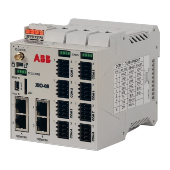
- Page 1 A BB ME ASU REME NT & AN ALY TICS | U SER M AN UA L Extendable IO (XIO) XIO-08 Smart, extendable IO Measurement made easy...
-
Page 2: Table Of Contents
— Contents Contents ............................. 2 List of tables ..........................7 Additional information ........................ 8 Cyber security ..........................8 Malware Prevention ......................... 8 Safety ............................9 Safety symbol conventions ....................... 9 Potential safety hazards ......................10 Compliance ..........................11 Waste Electrical and Electronic Equipment (WEEE) ..............11 FCC RF Compliance ....................... - Page 3 4.6.4 Configure the RMC ................... 49 Configure serial communication applications (COM ports) ........... 56 4.7.1 Configure COM port for communication with ABB devices ........57 4.7.2 Configure XIO application export ............... 69 4.7.3 Verify XIO application export on the RMC ............70 4.7.4...
- Page 4 5 Calibration ........................... 97 6 Basic troubleshooting ......................98 RMC unable to detect or communicate with the XIO ............98 6.1.1 Verify RMC-XIO connection (physical connection) ..........99 6.1.2 Verify the IP parameter configuration (IP communication) ........101 XIO applications not displaying on the RMC ..............104 RMC failure to receive data from XIO passthrough ............105 6.3.1 Missing or mismatched TCP port ...............106...
- Page 5 9.4.1 Security requirements before upgrade ...............163 9.4.2 When to upgrade ....................163 9.4.3 Software packages ..................164 9.4.4 Determine device software part number/version ..........164 9.4.5 Update software .....................166 System restart ......................167 9.5.1 Restart type overview ..................167 9.5.2 Warm restart with the RESET button ..............168 9.5.3 Warm restart from the device loader ..............169 9.5.4...
- Page 6 11.3 Wireless network communication ...................193 11.3.1 Local point-to-point wireless access to XIO (Wi-Fi AP) by host .......193 11.3.2 Local wireless access to RMC by host ..............194 11.3.3 Local wireless access to XIO (Wi-Fi client) by host ..........195 12 Product warranty ....................... 196 Contact us ..........................197 6 | XIO USER MANUAL | 2106424MNAA...
-
Page 7: List Of Tables
— List of tables Table 0-1: Related documents ....................... 8 Table 1-1: XIO models ....................... 12 Table 2-1: XCORE enclosures available ..................14 Table 2-2: Ethernet ports ......................18 Table 2-3: Power connector specifications ..................20 Table 2-4: Applications available with XIO ..................23 Table 3-1: Power source requirements .................. -
Page 8: Additional Information
ABB Inc. and its affiliates are not liable for damages and/or losses related to such security breaches, any unauthorized access, interference, intrusion, leakage and/or theft of data or information. -
Page 9: Safety
The content of these instructions is neither part of nor provided for changing a previous or existing agreement, promise, or legal relationship. All obligations of ABB result from the respective sales contract, which also contains the full and solely valid warranty clauses. These are neither limited nor extended by the content of these instructions. -
Page 10: Potential Safety Hazards
WARNING – Bodily injury. These symbols, and the signal word "WARNING", indicate a potentially dangerous situation. Failure to observe this safety information could result in death or severe injury. The text may state the hazard, how to avoid the hazard, and the result if not followed. -
Page 11: Compliance
Waste Electrical and Electronic Equipment (WEEE) EU Directive 2012/19/EU ABB Industrial Automation, Measurement and Analytics is committed to actively protecting the environment. Do not dispose of WEEE as unsorted municipal waste. Collect WEEE separately. WEEE management participation is critical to the success of WEEE collection. -
Page 12: System Description
— System Description The ABB XIO is a microprocessor-based device with built-in, pre-engineered applications for expanding communication and IO over Ethernet to a host controller. The devices are extendable, supporting hardware expansion using TFIO modules. XIO may be placed remotely from the controller (RTU) using Ethernet. Configuration of the device may be performed using USB, Wi-Fi, Bluetooth, or an Ethernet connection. -
Page 13: Physical Description
IMPORTANT NOTE: The XIO must be installed on an interior wall, or in an enclosure that meets the environmental ratings for the location. See section 2.1.1 Enclosures for information about ABB enclosures. See section 3.1.1 Enclosure requirements for information about third-party enclosures. -
Page 14: Enclosures
The grounding clips fit through the base grounding slots to contact the DIN rail when mounted. Be sure to ground the DIN rail. 2.1.1 Enclosures The XIO can be purchased installed in an enclosure. ABB offers the XCORE enclosures described in Table 2-1. For more information and complete specifications see www.abb.com/upstream. Table 2-1: XCORE enclosures available... - Page 15 Figure 2-3: XCORE 3630 medium size enclosure (front view) Figure 2-4: XCORE 2424 small size enclosure (internal view displays installed XIO) XIO USER MANUAL | 2106424MNAA | 15...
-
Page 16: Electronic Board
Electronic board The electronic board component specifications are listed in this section. DANGER – Serious damage to health / risk to life. Explosion Hazard: Do not connect or disconnect connectors or their terminations while energized unless the area is known to be non- hazardous. - Page 17 Port Connector Data transfer rate Use (connections) name type (port speed) 3 Mbps over Bluetooth Actual throughput-rate will be less depending on number of device connected, distance and obstacles between device antenna. USB Type Mini B Supports USB 2.0 full speed Local communication (high-speed mode and high-speed mode serial local operator interface)
- Page 18 Port RXD Activity Communications Port Group STATUS LEDs During normal operation LEDs 1-3 should be ON, LED 4 should be OFF. Figure 2-7: STATUS LEDs Legend: Status LEDs for all COMS Port Group Power On Port Group Power OFF (LED is OFF no other LEDs should be ON) Port Group Enabled Port Group Disabled (LED is OFF no Port LEDs should be ON) Port Group Normal operation...
-
Page 19: Tfio Expansion Interfaces
Port Data transfer rate (port speed) name B Network (1, 10/100 Mbps Full Duplex (supports auto- Two ports: B1 and B2. negotiation and uses standard or straight-through Realtime data communication between Ethernet cable) XIO and RMC. IMPORTANT NOTE: For additional details on Ethernet connections, refer to section 10 Ethernet connectivity scenarios, or click Help on the Networking tab when connected to the device with the... -
Page 20: Power Port
– LED light panel – Reset button – Module address selector For additional information, refer to the TFIO Module User Manual. See Additional information for a link to the online manual. Figure 2-9: TFIO module Legend: TFIO module Description Description 4 pin terminals TFIO front face Bus address rotary switch... -
Page 21: Security Switch
External power supply External power terminal connector XIO device IMPORTANT NOTE: If you do not use ABB-approved power sources, verify that the customer- supplied power source meets these requirements. For additional details about requirements, see section 3.1 Site planning and requirements. -
Page 22: Reset Button
Figure 2-11: Security switch Legend: Security switch Description Security switch Reset (paperclip actuated) Cold (paperclip actuated) 2.2.5 Reset button The XIO has a reset button located above the USB connector (Figure 2-11). DANGER – Serious damage to health / risk to life. Explosion Hazard: The RESET button must not be pressed unless the area is known to be non-hazardous. -
Page 23: Operating System
– Applications: Totalflow applications that define the XIO functions for the required scenarios – Configuration: Files that contain factory default and user-defined settings and parameters required by the applications active on the XIO The stored data depends on the configured applications for the specific site requirements. 2.3.1 Operating system The XIO uses a thread-priority preemptive real-time operating system (Linux-based OS). -
Page 24: Configuration Files
SSH provides an encrypted communication channel, which requires private key authentication for access to the controller. Secure access is available for troubleshooting purposes only and is reserved for advanced users and ABB technical support or development personnel. -
Page 25: Installation
WARNING– Bodily injury. Although there may be alternate methods of installation and commissioning of the XIO, ABB recommends that technicians perform the procedures in the order presented: plan, install, wire, then apply power, verify power-on sequence, and configure. Site planning and requirements XIO installation requires that customer-supplied enclosures, power sources, wiring, and location comply with the specifications described in this section. -
Page 26: Mounting Requirements
Basic hardware installation This is an overview of a typical hardware installation. For different installations, call the ABB main office number listed on the last page of the manual. 26 | XIO USER MANUAL | 2106424MNAA... -
Page 27: Ground The Controller
The XIO is usually already mounted on an internal DIN rail inside the enclosure. To use non-ABB enclosures, follow the vendor’s mounting instructions. The DIN rail can be installed on a wall or in an enclosure that meets the environmental ratings for that location. It is recommended that 4 inches of clearance be available above and below the device, and 1 inch to the left and right of the XIO, or the XIO and any TFIOs connected. -
Page 28: Wire Serial Communication Ports
Figure 3-1: XCORE enclosure top mounting tabs and interior view 3.4.4 Wire serial communication ports Wire the XIO serial communication (COM) ports to communicate with and power external devices. Wire for communication according to the type of serial interface with the external device. Wire for power if there is no external supply powering the external device. - Page 29 Figure 3-2: COM 1 to COM 8 serial communication port pinouts Legend: COM 1 to COM 8 serial communication port pinouts RS-232 RS-485 RS-422 Voltage out (VOUT) Voltage out (VOUT) Voltage out (VOUT) Ground (GND) Ground (GND) Ground (GND) Switched voltage (SW VOUT) Switched voltage (SW VOUT) Switched voltage (SW VOUT) Ground (GND)
- Page 30 NOTICE – Equipment damage. Do not push the ferrules too hard into the terminal connector. This can damage the connector or the ferrule. Wire remote communications equipment (radio) The serial communication (COM) ports can be wired with remote communication equipment, such as a radio.
-
Page 31: Connect Tfio Modules
As illustrated in the following drawing, do not connect A1 and A2 or B1 and B2 to the same Ethernet switch if they are in 1 Network Mode. Connecting both sets of ports to the same switch disables the ports. Figure 3-5: Wrong Ethernet connection 3.4.5 Connect TFIO modules... -
Page 32: Power The Xio
The TFIO modules are hot-pluggable and can be removed or detached when the XIO is powered. However certain locations and conditions may require powering off the XIO before TFIO module insertion or removal. DANGER – Serious damage to health / risk to life. Do not perform any wiring or removal/insertion of modules unless it is known that a potentially explosive atmosphere condition does not exist. -
Page 33: Power-On Sequence
NOTICE – Equipment damage. The maximum input voltage for legacy TFIO modules is 12 Vdc (see Additional information for a list of legacy TFIOs). IMPORTANT NOTE: Externally fuse the power input for the load. This consists of the equipment plus any external devices powered by the XIO. The wire gauge should be appropriate (in some applications a minimum of 16 AWG gauge is advisable). - Page 34 IMPORTANT NOTE: The external power supply must meet the specifications in Section 3.1.2 External power supply requirements. All wiring must comply with national and local electrical codes and applicable ABB certification drawings to maintain system certification. To wire an external power source to the XIO:...
-
Page 35: Startup
Online help topics are available for each PCCU screen. Download PCCU32 from the ABB global website The latest PCCU version is available on the ABB website. Always review release notes for new features or bug fixes before installing and using new versions. - Page 36 Figure 4-2: PCCU page - document downloads Figure 4-3: Release notes list 36 | XIO USER MANUAL | 2106424MNAA...
-
Page 37: Install Pccu32
PCCU32 software operates in a Windows ® environment. To install a PCCU32 installation file downloaded from the ABB website: Establish local communication Connect the laptop to the USB or Ethernet ports to establish initial local communication. These ports are configured at the factory for local operator access. Configure PCCU to use any of these ports. - Page 38 Table 4-1: USB cabling Host system Required cabling termination (connectors) or ABB part number interface type adaptors USB 2.0 Type A receptacle USB 2.0 Type mini-B plug to USB 2.0 Type A plug cable 1801800-xxx (referred as USB PCCU32 cable)
-
Page 39: Using The Ethernet Ports
Figure 4-6: Synchronize date and time Figure 4-7: XIO default screen – Entry mode (Advanced view) To use Ethernet, complete the steps in section 4.3.2 Using the Ethernet ports first, change to expert view (section 4.4 Change PCCU to Expert view), and then proceed to section Configure basic XIO parameters. - Page 40 The following table lists the cabling details for connecting to the XIO Ethernet ports. Table 4-2: Ethernet cabling Supported device Required cabling termination ABB part number (connectors) or adaptors (with Ethernet 10/100 BaseT ports) Host system (operator laptop or computer)
- Page 41 – If the laptop has a static TCP/IP configuration, configure it for dynamic IP addressing and private addressing as the example shows in figure (Figure 4-9). IMPORTANT NOTE: Detailed configuration steps for the host system vary depending on the operating system version. Typically, you can configure IP properties from the Windows Control ®...
-
Page 42: Change Pccu To Expert View (Required)
Figure 4-10: PCCU setup for local Ethernet communication Change PCCU to Expert view (required) Change the PCCU Entry screen to Expert view to complete the XIO startup and configuration procedures. This procedure assumes a successful PCCU connection with the device is already established. To change to Expert view from the Entry screen: Figure 4-11: Expert View screen 42 | XIO USER MANUAL | 2106424MNAA... -
Page 43: Configure Basic Xio Parameters
IMPORTANT NOTE: The Show editable fields option is available at the bottom of PCCU entry screens. When you select this option, user-configurable fields display white. Please note that when this option is selected, some fields that display function statuses may not show color. If you wish to show colors, then clear this option and always remember to click Re-read to refresh the screen. -
Page 44: Configure Network Communication (4-Port Switch Mode)
The recommendation is to turn synchronization on. If installing several XIOs for connection to an ABB remote controller, synchronizing each XIO to the controller means there is no need to individually synchronize each XIO to the laptop at first time connection. - Page 45 Figure 4-13: Ethernet connection – XIO / RMC (Star topology) Legend: Ethernet connection (Star topology) Name ID Name ID Name Host System with PCCU Ethernet switch or hub TCP/IP network Figure 4-14, the XIO connects directly to the RMC. Access to the XIO for remote management is through the RMC which performs the role of a switch.
-
Page 46: Configuration Overview
Figure 4-14: Ethernet connection – XIO / RMC (daisy chain topology) Legend: Ethernet connection (daisy chain topology) Name Name Host System with PCCU RMC (Ethernet ports configured in 1-Network Mode) TCP/IP network 4.6.2 Configuration overview The configuration procedures assume the following: –... -
Page 47: Configure The Xio
– If the XIO connects to a Totalflow controller, such as the RMC-100, follow steps in section 4.8.1 Configure the XIO first, and then complete steps in section 4.8.2 Configure the RMC. 4.6.3 Configure the XIO Configure the XIO with valid IP parameters. The XIO supports static (manual) or dynamic (DHCP) IP addressing on both A and B network ports. - Page 48 IMPORTANT NOTE: The factory default device name is a unique name specific to each XIO. While the name is user-configurable, it is recommended to leave the default to ensure that the name is always unique. The device name is the same as the Network ID (displayed in the Services tab). When the XIO wireless interface is enabled (for example, in the role of a Wi-Fi access point), it broadcasts this name.
-
Page 49: Configure The Rmc
Figure 4-17: Restart message IMPORTANT NOTE: Any existing TCP/IP connection is lost when the XIO IP address changes and the network interface restarts. If you are using one of the Ethernet ports to connect locally, reconfigure the laptop or PC with an IP address compatible with the new XIO IP address to reestablish connection. - Page 50 Figure 4-18: Auto discovery service enabled in the RMC Figure 4-19: Communication Setup (default screen) 50 | XIO USER MANUAL | 2106424MNAA...
- Page 51 Figure 4-20: Add/Modify Communications devices and application Select XIO Interface from the Application drop-down list. Select Network from the Port drop-down list. Leave the XIO Client (default) on the Protocol drop-down list. Click the Remote Service drop-down list. The list of detected XIOs in the field network displays: The XIO Server application displays with each associated XIO ID.
- Page 52 Figure 4-22: Default XIO Interface configuration 52 | XIO USER MANUAL | 2106424MNAA...
- Page 53 Figure 4-23: XIO Interface application on network port Figure 4-24: XIO Interface on the RMC navigation tree XIO USER MANUAL | 2106424MNAA | 53...
- Page 54 Figure 4-25: XIO Interface application on network port – additional settings 54 | XIO USER MANUAL | 2106424MNAA...
- Page 55 Figure 4-26: XIO Interface Overview screen Figure 4-27: Enable the XIO Interface scan function XIO USER MANUAL | 2106424MNAA | 55...
-
Page 56: Configure Serial Communication Applications (Com Ports)
Configure COM 1 - COM 8 communication ports to connect one or more peripheral serial devices. These ports are software-configurable to support RS-232, RS-422, and RS-485. Configure the ports with the application that supports the type of peripheral. For ABB Totalflow peripherals, use special-purpose communication applications such as the XMV Interface. -
Page 57: Configure Com Port For Communication With Abb Devices
Configure COM port for communication with ABB devices This procedure describes the configuration of an XIO COM port for connection with an ABB peripheral. The example in this procedure connects an ABB multivariable transmitter to XIO COM1. The XMV Interface is the application that handles communication with the multivariable. - Page 58 Figure 4-29: XIO Application/License Management tab Figure 4-30: Add New Application 58 | XIO USER MANUAL | 2106424MNAA...
- Page 59 Figure 4-31: XMV Interface selected from the application list Figure 4-32: XMV Interface instance on default application slot number XIO USER MANUAL | 2106424MNAA | 59...
- Page 60 Figure 4-33: XMV Interface on the XIO navigation tree Figure 4-34: XMV Interface communication setup (default screen) 60 | XIO USER MANUAL | 2106424MNAA...
- Page 61 Configure the serial port settings to match the settings of the external device. When the XMV application is added from the Application/License Management tab, the default settings may not require change. Some of these default settings have been optimized to work with ABB peripherals with only minor modification at first-time connection.
- Page 62 Figure 4-36: XMV Interface Communication Setup for XIO COM1 Figure 4-37: Refresh generic XMV Interface application to reflect associated port (XIO COM1) 62 | XIO USER MANUAL | 2106424MNAA...
- Page 63 Figure 4-38: XMV Interface application associated with XIO COM1 (navigation tree) On the navigation tree, expand the XMV Interface instance and then select XMV1. Select Setup tab. If the Scroll Displays field, in the XMV Displays section is enabled, change to Disabled. Click Send.
- Page 64 Communication Setup tab. When the port and application are assigned and added in this way, the default settings need to be updated. The default settings on this screen do not reflect the optimal values for ABB multivariable transmitters. Optimal values to complete the configuration of the port are provided in this procedure.
- Page 65 Figure 4-40: XIO Communication setup tab Select the COM port. Click Add New Device/Application. The Add/Modify Communication device and applications window displays (Figure 4-41). Figure 4-41: Add/Modify Communication devices and applications Select the appropriate application from the Application drop-down list. In this example, the selected application is the XMV Interface (Figure 4-42).
- Page 66 Select the appropriate protocol from the Protocol drop-down list. Figure 4-42: Add Application, Port, and Protocol Figure 4-43: Add XMV Interface for COM1 – default app name Type a unique port description in the Description field. The default description is the application name.
- Page 67 Configure the desired protocol if needing to change the initial selection. Figure 4-44: XMV Interface for XIO COM1 XIO USER MANUAL | 2106424MNAA | 67...
- Page 68 Figure 4-45: XMV Interface for XIO COM1 – default communication and format settings Expand the XMV Interface instance, then select Communications. The Setup tab displays with the port parameters for communication with the peripheral. Verify the configuration parameters. The Setup screen reflects the default parameter values from the Communication Setup tab and additional parameters.
-
Page 69: Configure Xio Application Export
Figure 4-46: XMV1 configuration On the navigation menu, select the XMV application instance. The main XMV screen displays. Verify that variable values display and that the poll counter displays polls. Click Re-read or select Monitor to update screen values. The number of errors counter should display zero or should not be increasing. -
Page 70: Verify Xio Application Export On The Rmc
Figure 4-47: Example of selected application to export – exported at application index 1 Figure 4-48 4.7.3 Verify XIO application export on the RMC Exported XIO applications display under the XIO Interface on the RMC navigation tree to help distinguish the XIO remote applications from the local applications. - Page 71 Figure 4-49: Verify XIO application displays on the RMC navigation tree Figure 4-50 displays both RMC and XIO navigation trees. The RMC should display all exported XIO applications. Figure 4-50: Exported XIO application visible on the RMC (left screen) XIO USER MANUAL | 2106424MNAA | 71...
-
Page 72: Configure Measurement Applications To Use Xio Values
Expand the XMV application for the port of interest. Select the remote multivariable of interest. For example, XMV1 (there may be multiple XMVs connected to a single COM port). View the values for DP, SP, and TF. Click Re-read to refresh to the latest values or select Monitor to keep track of latest values as they change. -
Page 73: Configure Ethernet-Serial Passthrough
Figure 4-52: Obtain RMC registers storing remote peripheral measurement values Figure 4-53: Configure registers storing remote peripheral measurement values Configure Ethernet-Serial Passthrough XIO USER MANUAL | 2106424MNAA | 73... -
Page 74: Configure The Xio
IMPORTANT NOTE: As an example, the scenario described in this section describes the configuration of an XIO COM port connecting to an ABB multivariable (XMV). An XMV Interface application instance is added on the RMC for communication with that device. Other scenarios might include multiple XMVs on the same COM port or additional XMVs connected to other ports. - Page 75 XIO USER MANUAL | 2106424MNAA | 75...
- Page 76 Figure 4-54: Adding Ethernet-Serial Passthrough application Figure 4-55: Assign COM port and protocol to Ethernet-Serial Passthrough 76 | XIO USER MANUAL | 2106424MNAA...
- Page 77 Figure 4-56: Ethernet-Serial Passthrough COM port assignment – Default settings Configure a new description that helps identify the assigned COM port if desired. Configure the TCP port in the Port field. Figure 4-57: Ethernet-to-Serial Passthrough TCP port assignment XIO USER MANUAL | 2106424MNAA | 77...
- Page 78 Figure 4-58: Ethernet-to-Serial Passthrough on the navigation tree – instance renamed Figure 4-59: Ethernet-Serial Passthrough application on XIO navigation tree 78 | XIO USER MANUAL | 2106424MNAA...
- Page 79 Figure 4-60: Ethernet-Serial Passthrough Setup – User defined Application Settings Type a new descriptive port name if necessary. Ideally, the description identifies the port the passthrough function is associated with. This will make port selection easier when configuring the communication application on the remote controller. Configure the TCP port.
- Page 80 Figure 4-62: Ethernet-Serial Passthrough for XIO COM2 (with user-defined name) Figure 4-63: Ethernet-Serial Passthrough (COM2) - Serial Port Setup 80 | XIO USER MANUAL | 2106424MNAA...
- Page 81 Figure 4-64: Attached Device drop-down list Figure 4-65: Configure XIO COM port communication values (Default values for the XMV) XIO USER MANUAL | 2106424MNAA | 81...
-
Page 82: Configure The Rmc
4.8.2 Configure the RMC The RMC detects the Ethernet-Serial passthrough application instance(s) when activated on the XIO. This procedure takes advantage of the RMC Auto discovery feature to assign a local communication application to a remote COM port on the XIO. To configure a serial communication application on the RMC for an XIO COM port: Figure 4-66: Add/Modify Communication devices and applications Figure 4-67: Assign XMV Interface to detected XIO port (shown in Remote Service field) - Page 83 Figure 4-68: XMV Interface assigned to XIO port – Default Application settings XIO USER MANUAL | 2106424MNAA | 83...
- Page 84 Figure 4-69: XMV Interface assigned to XIO port – User-defined application description Figure 4-70: XMV Interface on RMC navigation tree (with user-defined name) 84 | XIO USER MANUAL | 2106424MNAA...
- Page 85 On the navigation tree, select the application instance and then Communications. The Setup tab displays. Figure 4-71: XMV Interface Communications Setup with assigned XIO and COM port Configure the number of XMVs (if more than 1). When multiple XMVs connect to the port, each of the XMVs must display on the navigation tree for individual configuration and management.
-
Page 86: Configure The Peripheral
4.8.3 Configure the peripheral For ABB Totalflow peripherals, the controllers or flow computers may support peripheral configuration options within the applications assigned to those peripherals. In this example, the XMV Interface application on the RMC supports the XMV configuration of the multivariable connected to the XIO COM port. -
Page 87: Configure Measurement Applications To Use Xio Values
Figure 4-73: Verify RMC receives remote peripheral measurement values 4.8.4 Configure measurement applications to use XIO values To configure measurement applications with the remote XMV measurement values: Figure 4-74: RMC application registers storing remote peripheral measurement values XIO USER MANUAL | 2106424MNAA | 87... -
Page 88: Configure The I/O Interface For Tfio Module Support
Figure 4-75: Configure measurement value registers for measurement application IMPORTANT NOTE: Configure other applications as required. Application configuration details are beyond the scope of this manual. Application-specific topics are available on each application screen. Click Help on the for specific topics. Configure the I/O Interface for TFIO module support The XIO supports I/O expansion with TFIO modules. - Page 89 IMPORTANT NOTE: The Valve Control TFIO module is not supported by the XIO at initial product release. Support for this module is planned with future flash upgrades. Contact ABB technical support for additional information. DANGER – Serious damage to health / risk to life. Do not perform any wiring or removal/insertion of modules unless it is known that a potentially explosive atmosphere condition does not exist.
-
Page 90: Add And Export The I/O Interface Application
IMPORTANT NOTE: To remove TFIO modules insert a small slotted screwdriver between the connector and the housing and gently pry the module away from the XIO. Proceed to configure the I/O Interface application next. 4.9.2 Add and export the I/O Interface application IMPORTANT NOTE: For additional details supporting TFIO modules see the link to the I/O Interface Application Guide listed in Additional... -
Page 91: Verify Tfio Module Detection On Xio
Figure 4-79: Export I/O Interface application IMPORTANT NOTE: The index number an application is exported at affects register numbers for the XIO Interface application on the remote controller (RMC). If you change this number after the application has been added and configured, it changes its existing register numbers. Register number change for an application already in-service may disrupt operation. - Page 92 Figure 4-80: TFIO detection on the XIO – TFIO Module List tab Figure 4-81: TFIO Module State for new module - Available 92 | XIO USER MANUAL | 2106424MNAA...
- Page 93 Figure 4-82: TFIO Module State – Select Online mode Figure 4-83: TFIO Module State – Online mode If the state displays Normal (green), the XIO is successfully communicating with the remote controller and the TFIO is ready for use (successful network connectivity). If the state displays Alarm (red), the XIO is not successfully communicating with the remote controller or needs a reset.
- Page 94 IMPORTANT NOTE: The Fail-Safe Watchdog is enabled for all TFIO modules by default. Connecting a TFIO module without exporting the I/O Interface to the RMC sets the Watchdog state to alarm. The 3 and 4 Sys Status LEDs (located below the XIO security switch) blink to indicate this condition.
-
Page 95: Verify I/O Interface Application Export On Rmc
Click Send. Verify that the Watchdog State displays Normal (green). Figure 4-86: Fail Safe Watchdog tab – Watchdog in Normal state (Alarm cleared) 4.9.4 Verify I/O interface application export on RMC Refresh the navigation trees (Figure 4-87) to verify that the I/O Interface application displays (XIO tree view on the right). - Page 96 Figure 4-87: XIO I/O Interface application exported to RMC – Remote TFIO Module detected 96 | XIO USER MANUAL | 2106424MNAA...
-
Page 97: Calibration
— Calibration Calibration procedures vary depending on application scenarios. The XIO supports the same calibration utility as other Totalflow devices. Calibration depends on where the involved applications are in operation and the communication method between the XIO and the remote controller. The table below describes where the calibration must be performed from per application scenario. -
Page 98: Basic Troubleshooting
— Basic troubleshooting The following sections describe issues that may arise during basic installation. For support, call the ABB main office number on the last page of this manual. Before calling: – Take note of the model and serial number. The serial number is on a label affixed to the bottom of the unit. -
Page 99: Verify Rmc-Xio Connection (Physical Connection)
– Connectivity failure after an initially successful connection results from a change of connection status The XIO Interface Overview screen displays information about the last successful communication polls in addition to the red indicator for connection loss. Figure 6-2: XIO Interface Overview screen (connection failure) 6.1.1 Verify RMC-XIO connection (physical connection) Depending on the connection scenario, the XIO may connect to the field network switch (star topology),... - Page 100 Figure 6-3: RMC-XIO connection successful A broken connection, or one with excessive errors, displays communication status errors, poll state for reads constantly initializing but never reaching the Active state, and port status closed. Figure 6-4 shows the state of the status parameters when the connection is broken. Figure 6-4: RMC-XIO Connection failure If the connection status displays errors: 100 | XIO USER MANUAL | 2106424MNAA...
-
Page 101: Verify The Ip Parameter Configuration (Ip Communication)
If the Communication Status, Poll State and Port Status errors do not resolve and all the physical connections are correct. Proceed to verify the IP parameters in the next section. 6.1.2 Verify the IP parameter configuration (IP communication) Correct IP parameter configuration is required for RMC-XIO communication to work. This procedure describes how to verify the IP parameters on the XIO. - Page 102 Verify that the RMC has the correct XIO IP address If the XIO has a valid configuration, verify that the XIO IP address has been correctly configured on the RMC. A mismatch in configuration prevents connection. Follow this procedure if you added the XIO Interface from the RMC Application and License management tab and configured the IP address manually.
- Page 103 Figure 6-8: Connection failure - incorrect XIO IP in the RMC XIO Interface setup Figure 6-9: Manual correction of the XIO IP address in the RMC XIO USER MANUAL | 2106424MNAA | 103...
-
Page 104: Xio Applications Not Displaying On The Rmc
Figure 6-10: XIO Interface overview screen - RMC-XIO connection successfully established XIO applications not displaying on the RMC Non-exported applications may not display under the XIO Interface on the RMC (Figure 6-11). To manage the remote XIO applications from the RMC, those applications must be exported. Figure 6-11: Missing remote applications on the RMC XIO Interface To verify the application export setting: 104 | XIO USER MANUAL | 2106424MNAA... -
Page 105: Rmc Failure To Receive Data From Xio Passthrough
Figure 6-12: Exported check box Figure 6-13: Exported XIO applications available on the RMC RMC failure to receive data from XIO passthrough The RMC-XIO communication through Ethernet-Serial passthrough requires assigning the desired COM port, assigning a unique TCP port, and configuring the correct serial communication parameters. As with XIO USER MANUAL | 2106424MNAA | 105... -
Page 106: Missing Or Mismatched Tcp Port
any serial communication setup, parameters on the XIO must match the parameters of the RMC application that is processing the data received from the XIO COM port. If you are experiencing issues communicating when using the Ethernet-serial passthrough function, verify the configuration on the XIO first and then troubleshoot serial communication. -
Page 107: Missing Or Incorrect Xio Serial Port
IMPORTANT NOTE: The XIO supports pre-configured communication parameter values for several ABB peripherals. When connecting the XIO COM port to one of these devices, selecting the correct attached device type uses the optimal values to communicate with that device. For third-party peripherals, select Other and consult the vendor documentation for optimal values. -
Page 108: Incorrect Protocol Selection
Figure 6-17: Configure attached device type Figure 6-18: Configure COM port 6.3.3 Incorrect protocol selection Ethernet-Serial Passthrough supports the Passthrough or Modbus TCP Gateway protocols. Set the XIO for the Modbus TCP Gateway protocol only if the RMC communication application is setup as a Modbus TCP client. -
Page 109: Mismatched Serial Communication Parameters
Figure 6-19: Configure Protocol 6.3.4 Mismatched serial communication parameters If the configuration corrections in the previous sections do not resolve the communication failure, verify or correct the serial communication parameters. To verify or configure serial communication parameters: XIO USER MANUAL | 2106424MNAA | 109... - Page 110 Figure 6-20: Configure COM port Interface type Figure 6-21: Configure additional COM port parameters 110 | XIO USER MANUAL | 2106424MNAA...
-
Page 111: Fail Safe Watchdog Alarm Does Not Clear
Figure 6-22: RMC application able to receive data – XMV Interface displays XMV values Fail Safe Watchdog alarm does not clear Follow this procedure if the Fail-safe watchdog state remains in an alarm condition even after an attempt at manual recovery (the alarm won’t clear from Manual or Auto mode). IMPORTANT NOTE: The Fail-Safe watchdog feature monitors network connectivity between the RMC and the XIO. - Page 112 Figure 6-23: Fail-Safe Watchdog in Alarm State (Manual recovery mode) Figure 6-24: Fail-Safe Watchdog in Alarm State (Auto recovery mode) To clear the alarm: 112 | XIO USER MANUAL | 2106424MNAA...
- Page 113 On the navigation tree, select the XIO ID. Select the Application and License Management tab. Locate the IO Interface application in the application table. Select the Exported check box. Figure 6-25: Set XIO Applications to Export Click Send. XIO USER MANUAL | 2106424MNAA | 113...
- Page 114 Figure 6-26: Normal Watchdog State 114 | XIO USER MANUAL | 2106424MNAA...
-
Page 115: Additional Procedures
— Additional procedures Customize the XIO to meet individual site needs. Complete these steps in PCCU Expert view. Click View on the PCCU32 menu and select Expert from the drop-down list. Enable SSH/SFTP SSH/SFTP servers require a private key for authentication. The keys are in a protected storage location in the firmware (flash) and remain unchanged by software updates. - Page 116 Figure 7-1: Adding applications on the XIO – Application/License management tab 116 | XIO USER MANUAL | 2106424MNAA...
-
Page 117: Configure Security (Recommended)
— Configure security (recommended) To secure access to the XIO, review the security features implemented. Access points Totalflow user interfaces and host products support connection with the XIO through several types of communication ports, protocols, and services. These are points of entry that could be subject to inexperienced, unauthorized or malicious access through a point-to-point connection or a network connection. -
Page 118: User-Enabled Services
Table 8-2: Wireless interfaces in XIO Wireless Default Protocol Security feature available connections state communication interfaces Wi-Fi, Wi-Fi Access Point Disabled Totalflow Passcode protection and standards-based Wi-Fi functionality Local/TCP security modes (WPA, WPA2) Onboard Bluetooth, Disabled Totalflow Role-Based Authentication (RBAC) Port Name: Bluetooth Local 8.2.1... - Page 119 Default User- Port can Protocol Description port configurable using the closed port 65535 Device Loader Assigned to the device loader connections for device software update. PCCU requests this type of connection. 9696 SSH/TCP Assigned to secure shell (SSH/SFTP) connections. Third-party SSH/SFTP clients request these connections.
-
Page 120: Denial Of Service (Dos) Threshold Rates
Denial of service (DOS) threshold rates Protection of ports used for TCP/IP communication, such as Ethernet, is very important. Cybersecurity threats can make a device unavailable for connection. If the Totalflow device has a Denial of Service (DOS) attack, the device cannot grant requests for connection. -
Page 121: Configure Bi-Level Security With Security Switch
Recommendation Description Secure SSH/SFTP Enable the SSH/SFTP service only when required. access Change the default SSH/SFTP private keys for all accounts. The SSH/SFTP private keys should always be passphrase-protected. See section 8.7 Secure the SSH/SFTP service. Enable the Totalflow Software Update service only when required. Secure software updates Use RBAC to limit the ability to enable/disable this service. - Page 122 Legend: XIO security switch Description Description Antenna socket Reset button Security switch Cold button Figure 8-3: Station Setup tab – Security switch status IMPORTANT NOTE: Record the security codes. They are not visible on the Station Setup tab after you save them.
-
Page 123: Configure Non-Default Xio Security Code On The Rmc
8.5.1 Configure non-default XIO security code on the RMC The XIO Interface application requires read and write privileges to work properly with the XIO. If the XIO security level 2 code (write protection) is non-default, you must configure this code in the XIO Interface Communications Setup (in the XIO Security Code field). -
Page 124: Default Access Roles
RBAC security configuration restricts or disables unapproved applications and functions for the current user. Restricted applications and restricted functions are not visible on the PCCU32 navigation tree. The Send button is grayed out on applications with read-only functionality. NOTICE – Security override: Once implemented, RBAC overrides the device-enforced bi-level security and PCCU32-enforced security. - Page 125 Figure 8-5: Role based access control security editor Figure 8-6: RBAC role definition for XIO a. Verify that Role displays Administrator. b. Click Add User. Type the user name into the Name field. d. Type the password into the Password field. e.
-
Page 126: Edit The Security File
IMPORTANT NOTE: The Security Key displays at the top right corner of the Security Editor dialog. This key displays “n/a will be generated on save” before the security file is saved for the first time, or after changes. After saving, a new security key is assigned and logged into the Security Log. A copy of the security file is saved to the PC connected to the device. - Page 127 Figure 8-7: RBAC select XIO Figure 8-8: RBAC confirm XIO selection XIO USER MANUAL | 2106424MNAA | 127...
- Page 128 Figure 8-9: Add User in Security Editor Figure 8-10: Type user name and password 128 | XIO USER MANUAL | 2106424MNAA...
- Page 129 Figure 8-11: New user added to list in Security Editor IMPORTANT NOTE: During the initial setup, no customized roles exist. Create at least one additional user account before creating a customized role. Then assign the new role to a new or existing user account.
-
Page 130: Enable Rbac Authentication On Communication Ports
Figure 8-12: User role assignment 8.6.5 Enable RBAC authentication on communication ports Enabling RBAC authentication on communication ports secures access to the device. Connection to the ports requires authentication with correct credentials. Select one of the methods described in this section. Review the authentication options in Table 8-7. - Page 131 Figure 8-13: Enable port authentication from RBAC security editor Enable authentication from the Entry mode Enable RBAC authentication method for each required port. Use entry mode in Advanced or Expert view to configure or override communication port security: XIO USER MANUAL | 2106424MNAA | 131...
- Page 132 Figure 8-14: Enabling communication port authentication - Entry mode (on USB port) Use default RBAC credentials A login screen requires the User name and Password to connect PCCU to a flow computer through an RBAC-enabled port. Figure 8-15: Login dialog box Set the user name and password as default credentials in PCCU, if necessary.
-
Page 133: Secure The Ssh/Sftp Service
The table below lists the three SSH/SFTP accounts. Customers can access the Totalflow-user account, which is read-only. The developer and tech-support accounts are only available to ABB personnel for service and troubleshooting, or to advanced users and cybersecurity managers who want to generate private keys to replace factory default keys. -
Page 134: Ssh/Sftp Authentication
Authentication requires specific private-public key pairs for the type of access. ABB provides default private keys and passphrases to customers upon request. ABB stores the default public keys at the factory in a protected storage location on the device's flash. They remain unchanged by updates. - Page 135 new private key and its passphrase are necessary to access accounts after the update of a device‘s corresponding public key. To generate new keys: Figure 8-17: PuTTYgen Key Generator XIO USER MANUAL | 2106424MNAA | 135...
- Page 136 Figure 8-18: PuTTYgen Key Generator Key blank field 136 | XIO USER MANUAL | 2106424MNAA...
- Page 137 Figure 8-19: New public key XIO USER MANUAL | 2106424MNAA | 137...
- Page 138 Figure 8-20: New private key comment and and passphrase IMPORTANT NOTE: The PuTTY Key Generator generates the private key but does not display it on the screen. 138 | XIO USER MANUAL | 2106424MNAA...
- Page 139 Figure 8-21: Save private key and passphrase XIO USER MANUAL | 2106424MNAA | 139...
- Page 140 Figure 8-22: Select location to save private key file Figure 8-23: Copy public key from the Key field 140 | XIO USER MANUAL | 2106424MNAA...
- Page 141 IMPORTANT NOTE: If the public key text is not highlighted, right-click the text and click Select (Figure 8-24). Then click Copy. Figure 8-24: Select generated public key text IMPORTANT NOTE: Do not click Save public key on the PuTTY Key Generator dialog (Figure 8-25:).
- Page 142 Figure 8-25: Do not save public key from the PuTTY Generator dialog userkey.txt: A key with this name appends to the available Totalflow-user public keys in the • device. The Totalflow ® user account is accessible after the key update operation, either with the newly created private key or the previous set of private keys for the Totalflow-user account.
- Page 143 To save the public key: Figure 8-26: Enable the SSH/SFTP service XIO USER MANUAL | 2106424MNAA | 143...
- Page 144 Figure 8-27: FileZilla Site Manager connection setup Host: Type the device’s IP address. • Port: Type 9696. • Protocol: Select SFTP - SSH File Transfer Protocol from the drop-down list. • Logon Type: Select Key file from the drop-down list. •...
- Page 145 Figure 8-28: Type private key passphrase (password) Figure 8-29: Unknown host key warning XIO USER MANUAL | 2106424MNAA | 145...
- Page 146 Figure 8-30: FileZilla New Site window 146 | XIO USER MANUAL | 2106424MNAA...
- Page 147 Figure 8-31: Open the /Flash/AppData/.ssh/ directory XIO USER MANUAL | 2106424MNAA | 147...
- Page 148 Figure 8-32: Upload public key from laptop to device 148 | XIO USER MANUAL | 2106424MNAA...
- Page 149 Figure 8-33: Verify public key upload is complete XIO USER MANUAL | 2106424MNAA | 149...
- Page 150 Figure 8-34: Restart Totalflow device after public key update With the key upload complete, a new private-public key pair is available for authentication. Test the authentication with these new keys next. Verify authentication with new private-public key pair Verify that the public key update successfully established a new FileZilla SFTP connection with the new key and passphrase.
-
Page 151: Service And Maintenance
— Service and maintenance The Service and maintenance chapter provides: – Standard maintenance procedures, including software backup, restoration and upgrade – Additional procedures that are required before or after a maintenance procedure DANGER – Serious damage to health / risk to life. Do not perform maintenance when an explosive atmosphere is present. - Page 152 Figure 9-1: Collect icon Figure 9-2: Collect screen IMPORTANT NOTE: The data file might be in a default or user-defined location based on the PCCU directory path setup (Figure 9-3). The path for collected data is the Data File Path. The default location for data or laptop files is the pccudata directory in PCCU the installation directory.
- Page 153 Figure 9-3: Data file path Open File Explorer. Navigate to the data file path. (Figure 9-4). Locate the data file. The data file is named with the device’s station ID. Figure 9-4: Locate laptop file (collected data) IMPORTANT NOTE: PCCU creates a new laptop file the first time it collects data from a device. PCCU overwrites the data on the existing laptop file in subsequent collections from the same device.
-
Page 154: Save The Device Configuration
9.1.2 Save the device configuration The following procedures are required to save the configuration of the Totalflow device for backup purposes. The device stores a running (warm) and a startup (cold) configuration that contain configuration files for all enabled and active applications. Configurations performed after the device starts for the first time continue to run in the running configuration. - Page 155 IMPORTANT NOTE: If calibration files are in the startup configuration, they are automatically in the configuration package. The saved calibration files link to the device’s electronic board serial number and do not apply to any other device. To save the device configuration: Figure 9-6: 32 Bit Loader icon A message box displays (Figure...
- Page 156 IMPORTANT NOTE: Click Help on the 32-Bit Loader screens for additional details. Figure 9-9: Device loader Figure 9-10: Device loader Save service 156 | XIO USER MANUAL | 2106424MNAA...
- Page 157 Figure 9-11: Save Software From Device dialog Figure 9-12: Save the startup (cold) configuration from the loader XIO USER MANUAL | 2106424MNAA | 157...
- Page 158 Figure 9-13: Default destination folder to save configuration (PackageDir) Figure 9-14 : Loader status logs – config file save successful 158 | XIO USER MANUAL | 2106424MNAA...
-
Page 159: Restore The Device Configuration
Figure 9-15: Locating saved configuration (default directory) Restore the device configuration Use the device loader to restore the configuration on the device with a previously saved configuration package. Verify that the configuration package originated from the same unit. Then restore the device in the event of file corruption or other problems. - Page 160 Figure 9-16: Browse for configuration package Figure 9-17: Loader screen configuration package to restore 160 | XIO USER MANUAL | 2106424MNAA...
- Page 161 NOTICE – Tainted results. Do not select the calibration configuration in the Package field if the configuration package came from another XIO. Calibration files from a different device corrupt the last calibration records and skew the results. Only restore calibration files to the unit that generated them.
-
Page 162: Use The Configuration From Another Xio
Use the configuration from another XIO This procedure uses the device loader to copy a configuration saved from one device to another unit. Use this procedure if the configuration in several devices is similar. The configuration can be shared from one unit to another but not the calibration. -
Page 163: Update Device Software
Calibration files from a different device corrupt the last calibration records and skew the results. Only restore calibration files to the unit that generated them. Update device software ABB periodically releases software update packages. Use the device loader to update the controller with new software packages when required. 9.4.1 Security requirements before upgrade Before upgrade, disable the physical security switch on the device (set to unlock/off). -
Page 164: Software Packages
XIO package containing both OS and Flash is 2106200. A package numbered 2106200-029 reflects build 29 of that package type. Package part numbers are different for each product type. To locate packages on the ABB website, select the product and the applicable package. - Page 165 Figure 9-23: XIO registry tab IMPORTANT NOTE: Software part number and version information is also available from the loader. The loader screens use “App” to refer to the flash. See (Figure 9-24). Figure 9-24: XIO software part numbers from the Loader XIO USER MANUAL | 2106424MNAA | 165...
-
Page 166: Update Software
9.4.5 Update software To update the software: NOTICE – Loss of data. Collect the data and perform the procedures in section 9.1 Preserve data and configuration to back up the customer data and device configuration before performing any service on the device. Failure to collect data and save the configuration can result in a loss of data and require a complete system configuration. -
Page 167: System Restart
Review the implications of each restart type carefully to select the appropriate method. There may be several methods for the same type of restart. IMPORTANT NOTE: While there are several methods for the warm and cold restarts, ABB recommends restarts from PCCU32 (Entry mode or device loader). -
Page 168: Warm Restart With The Reset Button
(col Only as part of a service or configuration. maintenance procedure or when Restarts with startup (cold) ABB technical support specifically configuration. directs it. A cold restart causes running configuration loss (this might also include calibration files). To back up... -
Page 169: Warm Restart From The Device Loader
This procedure uses the RESET button on the XIO to restart the device. It causes the device to restart with the running (warm) configuration. If the XIO is installed inside an enclosure, you must have access to the interior of the enclosure to access the XIO reset button. To complete a warm restart using the reset button: Figure 9-27: Security switch Legend: Security switch... -
Page 170: Warm Restart From Pccu Entry Mode
Figure 9-28: Warm restart with device loader 9.5.4 Warm restart from PCCU Entry mode To restart the device from PCCU Entry mode: Figure 9-29: Warm restart on the Station Setup tab (Expert view) 9.5.5 Warm restart from terminal mode This procedure performs the warm restart from the terminal mode. It causes the device to restart with the running (warm) configuration. -
Page 171: Cold Restart From The Device Loader
This procedure performs the cold start from the 32-bit loader. Follow this procedure on a local or remote loader connection. However, ABB highly recommends performing the cold restart locally. The cold restart causes the device to restart using the startup (cold) configuration. -
Page 172: Cold Restart From Terminal Mode
This procedure performs the cold start from the terminal mode. It causes the device to restart using the startup (cold) configuration. Perform the procedure on either a local or remote connection. However, ABB highly recommends local cold restarts with this method. Invoke Terminal mode from entry mode or from the PCCU main screen. This method of cold restart requires command entry. -
Page 173: Factory Restart From The Device Loader
Figure 9-33: Terminal menu option Figure 9-34: Terminal screen – cold boot 9.5.8 Factory restart from the device loader This procedure uses the 32-bit loader to restore the device's startup configuration to its factory defaults. Factory defaults can include a generic base configuration or a custom configuration. Customers can request custom configurations to address specific requirements in addition to the basic configuration. -
Page 174: Remove And Restore Power
Figure 9-35: Factory restart using the device loader Remove and restore power NOTICE – Equipment damage. Remove the external power connections before removing all other cables, boards, and field connections. Connection or disconnection of cables and wires on the electronic board while power is connected can damage the electronic components. 9.6.1 Remove power from the device It might be necessary to remove power from a device for maintenance. -
Page 175: Reconnect Power To The Device
9.6.2 Reconnect power to the device Follow this procedure to reconnect the power port terminal connectors or the power cables back into the XIO. You do not need to rewire if the connectors are not removed from the cables. This procedure assumes wiring was left intact before terminal connector removal. -
Page 176: Return Device For Repair
Return device for repair Securely wrap the XIO in protective anti-static packaging before returning it for repair. Call the ABB main office number on the last page of this manual and ask for a Return Authorization number (RA). Affix the number to the outside of the return package. -
Page 177: 10 Ethernet Connectivity Scenarios
— 10 Ethernet connectivity scenarios ABB Totalflow equipment with onboard Ethernet ports supports TCP/IP-based communications. Some devices have multiple Ethernet ports, which provide additional possibilities for Ethernet connections. This section describes several Ethernet connection types or scenarios that are helpful when planning field installations, local configuration and monitoring, remote management over a network, and connection of additional equipment. -
Page 178: Ethernet Modes
– Other ABB or third-party control or peripheral equipment with Ethernet ports: for a variety of field peripheral equipment such as measurement devices. Peripherals must have an Ethernet port for direct connection. -
Page 179: Ip Parameter Configuration
10.2.2 Dynamic and static addressing ABB Totalflow devices with Ethernet ports support both dynamic and static IP addressing standard methods of IP configuration. Select what is appropriate for the field conditions. XIO USER MANUAL | 2106424MNAA | 179... -
Page 180: Private And Public Addressing
IP address to communicate with a device in the field. IMPORTANT NOTE: All ABB Totalflow devices have the same default address. If a field location requires network communication, and more than one device is installed at that location, the default address in each device must be changed to a unique and valid IP address. -
Page 181: First-Time Local Communication (4-Port Switch Mode)
Request a valid IP address from the network administrator and configure manually if you do not use DHCP. ABB recommends public addresses when multiple devices on the site require Ethernet connectivity. Each device must have a unique valid IP address assignment. Public addressing replaces default IP addresses on the devices, which are then no longer in effect. -
Page 182: Configuration
Figure 10-2: Local connection to XIO on 4-port switch mode Legend: Local connection to XIO on 4-port switch mode Number Description Local connection device Connection to network A (either port is usable) Connection to network B (either port is usable) 10.3.1 Configuration First-time configuration of local communication using Ethernet requires that:... -
Page 183: Network Communication For Switched Mode
Item Laptop PCCU connection setup Network (IP) For operating systems older than Leave defaults: Parameters Windows 98, manually configure ® IP address: a private address from the APIPA 169.254.0.13 block, for example 169.254.0.12. Subnet mask: For Windows ® 98 operating system 255.255.0.0 or newer, the laptop auto- configures its IP address if set for... -
Page 184: Local Access By Host
Figure 10-3: RMC on 2-Network mode supports local access only Legend: RMC on 2-Network mode supports local access only Name Name Customer (TCP/IP) network RMC: E2-LAN RMC: E1-LAN Local host system with PCCU Figure 10-4 shows that remote access is only available to the RMC. Access to the XIOs is not possible in this scenario as the RMC does not route between E1 and E2. - Page 185 connecting to the common network the switched-mode interfaces provide. See the logical equivalent of this configuration in Figure 10-6. Figure 10-5: Local access by host – supported physical connections (daisy-chain topology) Legend: Local access by host – supported physical connections (daisy chain topology) Name Name ID Name...
-
Page 186: Remote Access By Host
Figure 10-6: Local access by host – Logical connections to all daisy-chained devices Legend: Local access by host – Logical connections to all daisy-chained devices Name ID Name Host system with PCCU Field Network (all devices, same subnet) Customer (TCP/IP) network 10.4.3 Remote access by host Network communication is necessary for remote management of the device over a TCP/IP network... - Page 187 Figure 10-7: Remote access by host - supported physical connections (star topology) Legend: Remote access by host – supported physical connections (star topology) Name ID Name Name Host System with PCCU Field Ethernet switch XIO (Network connection on A1) Customer (TCP/IP) network 4 RMC-100 Host connects to XIO daisy-chained to RMC Figure 10-8...
- Page 188 Figure 10-8: Remote access by host – supported physical connections (daisy chain topology) Legend: Remote access by host – supported physical connections (daisy chain topology) Name Name Host system with PCCU RMC (Ethernet ports configured in 1-Network Mode) Customer (TCP/IP) network Figure 10-9 shows the logical network equivalent to the connections shown in Figure 10-7...
-
Page 189: Device-To-Device Communication
Configuration Remote communication over a TCP/IP network requires that: – Valid IP addresses are available for both the laptop and the XIO. – Network equipment is available (with links that are active and reliable), or additional equipment supports daisy-chain connections. –... -
Page 190: Enterprise And Industrial (3-Network) Support
(supporting device-to-device communication flows). This scenario supports complex applications with several XIOs and where there is need to isolate XIOs in separate subnets or domains within in the field. Consult with ABB Technical Support for more details. -
Page 191: Configuration
Traffic in each network is isolated to that network. The XIO does not route traffic between interfaces. This scenario supports complex applications with several XIOs and where there is need to isolate XIOs in separate subnets or domains within in the field. Consult with ABB Technical Support for more details. -
Page 192: Wi-Fi ® Connectivity Scenarios
— 11 Wi-Fi connectivity scenarios ® The XIO supports Wi-Fi wireless access by Wi-Fi clients. It can also connect to a Wi-Fi access point as a ® client. Wireless support depends on the Wi-Fi mode of operation configured on the XIO. IMPORTANT NOTE: A wireless network made available by enabling Wi-Fi on Totalflow devices is for the purpose of local access by hosts only. -
Page 193: Ip Parameter Configuration
Wi-Fi Mode Connection Description Access Point [Wi-Fi client]-to-XIO Wireless client joins the network advertised by the XIO. (AP) Bridged Wi-Fi clients can connect to the XIO over that network. 11.2 IP parameter configuration Connections over Wi-Fi networks are TCP/IP based. Each device connecting to a wireless network must have a unique and valid IP address. -
Page 194: Local Wireless Access To Rmc By Host
Figure 11-1: XIO Access Point: local access by operator – When there are several XIOs, one may be configured as an access point and the others as clients. In this scenario, the Wi-Fi client only joins a single wireless network, but can establish connection to all XIOs on that network. -
Page 195: Local Wireless Access To Xio (Wi-Fi Client) By Host
Figure 11-3: Local wireless access to an RMC (through an XIO) 11.3.3 Local wireless access to XIO (Wi-Fi client) by host Figure 11-4 depicts local wireless access by a Wi-Fi client to an XIO in client mode (XIO_02) and to an XIO in access point bridge mode (XIO_01). -
Page 196: 12 Product Warranty
— 12 Product warranty Before installation, store the equipment referred to in this manual in a clean, dry environment, per the Company's published specification. Make periodic checks on the equipment's condition. In the event of a failure under warranty, provide the following documentation to support your claim: –... -
Page 197: Contact Us
We reserve the right to make technical changes or modify the contents of this document without prior notice. With regard to purchase orders, the agreed particulars shall prevail. ABB does not accept any responsibility whatsoever for potential errors or possible lack of information in this document.