
Related Manuals for N&W Global Vending Canto Plus Instant


Summary of Contents for N&W Global Vending Canto Plus Instant
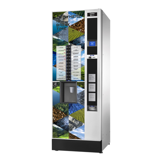
- Page 1 InstallatIon, oPERatIon, MaIntEnanCE Canto Plus Instant English H 3375EN 01 07 - 2010 dition...
- Page 3 Italiano Direttive europee European directives English Français Deutsch Español Português Nederlands Italiano Harmonised standards tions English Français Deutsch Español Português Nederlands ANTONIO CAVO...
-
Page 4: Eclaration Of Conformity
Declaration of conformity for use T�� ������� ��� b� �s�� b� �������� ��� b� ������ having reduced physical, sensorial or mental skills under ��� s����v�s��� �� ������ ��s���s�b�� ��� ����� s����� �� T�� ����������� �� ���������� ���� ��� �������� ������ ��... -
Page 7: Table Of Contents
English tablE of CoNtENts PagE PagE Eclaration of conformity illEr arnings tatistics INtroduCtIoN ndividual pricE anagEmEnt of changE tubEs dEntification of thE machinE EmpEraturE display n casE of failurE Est dispEnsing ransport and storagE prEalarms ositioning of thE vEnding machinE Evadts transfEr EcHNical fEaTurEs... -
Page 8: Introduction
IN CasE of faIlurE In most cases, any technical problem can be solved by Introduction carrying out minor operations. as a consequence, we suggest carefully reading this manual before contacting the technical documentation supplied is an integral the manufacturer. part of the equipment and it must therefore accom- In case of failures or malfunctions that can not be solved, pany the equipment whenever it is either moved please apply to:... -
Page 9: Ositioning Of The Vending Machine
tECHNICal fEaturEs PosItIoNINg tHE VENdINg maCHINE the machine is not suitable for installation outdoors. It Height 1830 must be installed in a dry room at a temperature ranging from 2°C to 32°C. It can not be installed in a room where Width water jets are used for cleaning (e.g. - Page 10 oiN Box afETy DEvicEs Made of galvanised sheet iron. Cover and lock available Door switch as accessories. Boiler safety thermostat manually reset aTEr supply air-break float jam supplied by the network, the water pressure of which lies anti-flood solenoid valve between 0.05 and 0.85 MPa (0.5 and 8.5 bar) the machine software can manage the water supply Float controlling liquid waste...
- Page 11 oNTaiNEr capaciTy lEcTric ENErgy coNsumpTioN Containers having a 2.5, 4.5 or 6 l capacity can be the electric energy consumption of the machine will mounted for instant products, according to models. depend upon many factors such as the temperature and ventilation of the room where the machine is installed, the inlet water temperature, the boiler temperature, etc.
-
Page 12: Ariable Combination Lock
varIaBLe ComBInaTIon LoCK to change the combination: - open the machine door to avoid forcing the rotation; some models are supplied with a variable combination lock. - slightly lubricate by using a spray inside the lock; the lock is complete with a silver key for normal opening - Insert the current change key (black) and turn it until and closing operations. -
Page 13: Filling And Cleaning
Chapter 1 filling and cleaning the machine is not suitable for installation outdoors. It must be installed in a dry room at a temperature ranging from 2°C to 32°C. It can not be installed in a room where water jets are used for cleaning (e.g. large kitchens, etc.). door swItCH Whenever you open the door, a special switch will power off the electric installation of the equipment to allow the... -
Page 14: Controls And Information
CoNtrols aNd INformatIoN loadINg the machine shall work at a room temperature between 2 and 32 °C. the cup dispenser shelf has got a double articulated the controls and information for the user are arranged joint intended to improve the accessibility to the cup dis- outside the door (see fig. - Page 15 ClEaNINg ugar the sugar container can be located on the cup shelf (see fig. 8) or with the other powder containers, accord- olour coDE ing to models. to make cleaning operations easier, the parts to be the sugar conveyor and slide shall be cleaned at regular cleaned and sanitised at regular intervals can be identi- intervals.
- Page 16 To disassemble the impellers, pull slightly to release ispensing coMpartMent anD vanDal proof De them (fig. 10 ); vice To disassemble the dispensing compartment, act on the retain hook at the back to release the compartment and let it slide on the guides. The doors intended to protect the openings for dispensing drinks and cups require no special maintenance.
-
Page 17: Installation
door swItCHEs Chapter 2 Installation aiNs Whenever you open the door, a special switch will power off the electric installation of the equipment. Installation and any subsequent maintenance opera- to power on the machine when the door is open, just tion must be carried out when the machine is live and, insert the key into the slot (see fig. -
Page 18: P Late Insertion
labEl INsErtIoN umEric sElEcTioN moDEls to insert the product labels, remove the metal sheet to insert the selection labels, disassemble the left side pushbutton panel protection by loosening the fastening panel from the door by removing the 5 screws complete- screws. -
Page 19: Water System Connection
watEr sYstEm CoNNECtIoN the vending machine must be connected with the drink- able water system according to the provisions in force in the place of installation of the equipment. the mains pressure must range from 0.05 to 0.85 Mpa (0.5 8.5 bar). let water come out of the water network until it is limpid and free of any trace of dirt. -
Page 20: E Lectrical Connection
ElECtrIC CoNNECtIoN aymENT sysTEm assEmBly the machine is arranged for electrical operation at a the machine is sold without any payment system. 230 V~ single-phase voltage and it is protected by a 15a as a consequence, only the installer will be liable fuse. -
Page 21: Illing The Water Circuit
fIllINg tHE watEr CIrCuIt saNItIsINg mIxErs aNd food CIrCuIts for tHE fIrst tImE If the air-break should signal no water for over 10 sec. as soon as you power on the machine, the machine will as soon as you install the machine, carefully disinfect automatically perform an installation cycle, i.e.: the mixers, the tubes intended to dispense instant drinks in order to guarantee the hygiene of dispensed products. -
Page 22: Operation
oPEratIoN up sENsor some models are equipped with a cup sensor intended to detect the presence of any object that may be placed omparTmENT covEr between the reflex reflector and the sensor itself. the machine is complete with a cup shift arm that can the sensor is provided with two lEDs intended to signal keep the dispensing nozzles very close to the drink, thus the state:... -
Page 23: I Nstant Dispensing Cycle
INstaNt dIsPENsINg rEsElEcTioNs Every single instant mixer is supplied by a direct current Preselections will vary according to the layout you may pump on the boiler. have set up on the machine. the preselections arranged The pump rotation speed and flow rate are controlled for every single layout are specified by the selection electronically to guarantee the best dose constancy and dose table (selection layout) supplied with the machine. - Page 24 usTomisiNg DriNks aTEr TEmpEraTurE rEgulaTioN If you customise drinks by considerably changing the the boiler temperature is controlled by the software: water dose, check the water flow rate in the mixer. If nec- -95° C for the espresso boiler essary, replace the nozzle with a more suitable one. -85°...
-
Page 25: Programming
PowEr oN Notes on Whenever you power on the machine, the display will Programming show the software release number. the electronics intended to control the machine will en- Canto able the operator to use many functions or not. software rev. x.x the machine programme is intended to describe all machine board rev. -
Page 26: Normal Operation Mode
NaVIgatIoN Normal oPEratIoN modE the message requiring the user to select a drink will ap- the interaction between the system and the operator pear on the display during the normal operation. occurs through the following components:: the key function may vary according to the layout and dIsPlaY the choices you have made during programming. -
Page 27: Eyboard
fIllEr mENu KeYBoarD according to models, the external keyboard may be by Press the programming button on the machine door way of direct selection or, as an alternative, with numeric once to set the machine to the “filler menu” mode. keys. - Page 28 the machine code, the date and the software release maNagEmENt of CHaNgE tubEs will be also printed. to print, act as follows: this function is active only if the payment system from the print function press key � to display “Do you you have set up can perform this operation.
- Page 29 tECHNICIaN mENu PaYmENt sYstEms the main software functions required to manage the ma- You can decide which protocols to enable for the pay- chine operation as well as possible are briefly explained ment systems available and manage the relative func- here below.
- Page 30 xEcuTivE The BDV protocol menus will enable the user to define ErsioN the following functions. You have to choose among the following payment sys- mmEDiaTE cHaNgE tems for the Executive system: the amount relative to a selection is generally cashed standard after the machine has sent the “successful selection”...
- Page 31 “ ” ExacT amouNT valuE Used to define the combination of empty tubes intended The MDB protocol menus will enable the user to define to set the coin mechanism to the “exact amount” mode. the following functions. all possible combinations of empty tubes are listed here mmEDiaTE cHaNgE below.
- Page 32 oiNs rETurNED arallEl macHiNE Used to define which coins shall be used to give the Function used to enable the presence of a validator or change among those available in the tubes. this param- parallel bill reader to recharge the keys. eter is active only with the coin mechanisms not intend- xacT cHaNgE EQuaTioN ed to manage the choice of the tube in use automatically...
- Page 33 PrICEs dosEs From this menu you can set up prices individually (for This group of functions is intended to define all variables every single selection) or globally (the same price for contributing to the drink build-up. all selections) and define the ranges of the promotional time band.
- Page 34 ixEr aTEr DosEs to dispense water, act on the following parameters: ixiNg moDE (0 - 3) For every single selection you can set the duration of the vENT TarT mixing cycle for every single water dose composing the set this value to dispense the water of the relative ingre- selection.
- Page 35 rippiNg NgrEDiENT moTor caliBraTioN to convert the product dose values properly, set up the You can define the wait time (you can programme it from flow rate value of every single ingredient motor in gr/s to 0 to 2000 hundredths of a second) from the end of deliv- calculate the grams to be dispensed.
-
Page 36: Machine Configuration
maNagEmENT maCHINE CoNfIguratIoN this group of functions is intended to manage the basic this group of functions is intended to check all param- data of the machine operation. eters relative to the operation of the machine. NiTialisaTioN this function shall be used in case of a memory data MaCH I nE C onF IG UR at I on error or if the software is replaced. - Page 37 isplay aNagEmENT this group of functions controls all display parameters. assWorD aNguagE It is a 5-digit numeric code you are required to enter to Use this function to select the language you wish to use display all “advanced” functions. to display the messages among those made available by the value of this code is set to 00000 by default.
- Page 38 asHiNg ccEssoriEs NaBlE THE WasHiNg kEy Use this function to enable the operation of the button Use this function to define whether the vending machine intended to wash mixers. is supplied by the network or by internal tanks: they key is generally disabled. 0 - water supply from the network;...
- Page 39 up TurrET TimE asTEr lavE Use this function to determine the rotation stop delay the control system of the machine is arranged for bank time of the cup stacker to balance any inertia due to the connection with other automatic vending machines (Samba, Samba Top and Diesis) type of cup.
-
Page 40: Est
acHiNE sErial NumBEr tEst Use this function to change the eight-digit numeric code intended to identify the vending machine (default set to t Est t Est DIs PE n sIn G rogrammiNg THE opEraTor coDE s PECIa l F Un Ct Ion s When the display is set to the “operator Code”... - Page 41 uToTEsT statIstICs Function used to check the operation of the main com- ponents of the machine semiautomatically. Press the lEcTroNic couNTEr Enter key to display the “AUTOTEST” message flashing on and off. o Display THE ElEcTroNic couNTEr You can renounce any operation and move to the next an electronic counter is intended to store all the dispens- one by pressing the exit key.
- Page 42 isplay gENEral no parameter can be configured for this protocol: Press the Enter key � to display the data you have stored in sequence, i.e.: aTa TraNsmissioN 1 - counter by single selection; Function used to select which communication interface 2 - counter by band;...
- Page 43 EsET rElaTivE proTocol auDiT Statistics can be reset either globally (all types of data) aud.1 money in the tubes or selectively, i.e. by: Money currently available in the change tubes - selections aud 2 money to the tubes - discounts-overprices Money conveyed to the change tubes - failures aud 3 money to the coin box...
- Page 44 CommuNICatIoN (global system for mobile communications) the control software can send a signal of faulty machine, “prealarms” or “ending product” via GsM modem after Co M M U nI Cat I o n a (programmable) well-defined number of dispensing UP - K E Y cycles of a given product.
- Page 45 rapHical scrEEN faIlurEs the machine is equipped with several sensors intended NaBlE isaBlE to control the various functional units. to manage the communication between CPU and as soon as a malfunction is found out, the type of failure graphical screen, if any on the machine. the function is is displayed and the machine (or part of it) is set out of disabled by default.
- Page 46 o cups offEE uNiT DispENsiNg uNiT failurE as soon as the no cups microswitch is opened, the cup the control micro signals that the espresso unit is han- stake shift motor is actuated. the machine is put out of dled during the brewing cycle. order if the microswitch has not closed after a complete offEE uNiT DiscHargE uNiT failurE...
- Page 47 1 - 9 f osEr aulT olD prEssurE sWiTcH If the current input of the ingredient motor should fall For models with a cold unit only. outside the range of default values, all the selections Cold selections are disabled if the pressure switch at the involving that doser will be disabled.
-
Page 48: Eneral I Ntroduction
PeriodiCal oPeraTionS Chapter 3 Maintenance Clean and disinfect the whole circuit and the parts in contact with the foodstuffs at least every year or more frequently, according to the utilisation of the machine or The intactness of the machine and its compliance the inlet water quality. -
Page 49: Channels And Mixers
ChannelS and MixerS To disassemble the impellers, just lock and pull slightly to release them (fig. 26); At regular intervals, it is necessary not only to remove any powder residue from the parts outside mixing units, in particular in the funnel area, but also to sanitise the mixer parts in contact with the drink. -
Page 50: Cup Dispenser
CuP dIsPENsEr ixEr NozzlEs If it had been necessary to disassemble the instant shelf, the cup dispenser is conceived in such a way that it can pay attention to the nozzle/pump combination in use be easily disassembled for maintenance operations. before during the reassembly phase. -
Page 51: Product Containers
ProduCt CoNtaINErs BoIlER MaIntEnanCE Descale the boiler at regular intervals, according to the - Remove the containers from the machine; hardness of the mains water and the number of selec- disassemble the product outlet ports and extract the tions you have performed. augers from the rear side of the container;... - Page 52 Important!!! NsTaNT BoilEr If the boiler heating system should work without water for Anti-boil thermostats (manually resettable) will deacti- any reason whatsoever, check the proper operation of vate the boiler heating element as a result of a failure of the boiler temperature probe before setting the machine the control system.
-
Page 53: Board Function
board fuNCtIoN programmiNg after having loaded the software, use the new board to CoNfIguratIoN of ElECtroNIC define which type of keyboard to use before initialising or programming the various parameters. boards to access the pre-programming function (keyboard the electronic boards are designed to be used on sev- choice), hold down the pre-programming button (see fig. -
Page 54: C.p.u. Board
C.P.u. board The C.P.U. (Central Process Unit) board can manage all the users arranged for the maximum configuration as well as the signals coming from the keyboard and the payment system. It can also manage the actuation board. the lEDs can supply the following information during the operation: The green LED (26) is flashing on and off during the normal operation of the C.P.U. -
Page 55: Actuation Board
aCtuatIoN board This board (see fig. 34) is intended to activate the 230 V~ users through relays and the direct current motors directly. Moreover, it can manage the signals from the cams and/or microswitches on the various users. Moreo- ver, it can control the instant boiler relay. the board is supplied at 24Vac. -
Page 56: Instant Boiler Control Relay
INstaNt boIlEr CoNtrol rElaY this relay is intended to control the trip of the instant boiler heating element. CurrENt rEgulator board the current regulator board will supply lighting lEDs by means of direct current. the board will provide for the constant brightness of aesthetic panels. -
Page 57: Water Circuit
watEr CIrCuIt Mixer Water inlet solenoid valve Boiler tray Mixer nozzles Dispensing nozzles Pumps Liquid waste bucket Air break Safety thermostat Instant boiler Anti-boil thermostats Boiler tray Hot water cock (optional) Air-break © by N&W GLOBAL VENDING S.p.A. 07 - 2010 3375 - 01... -
Page 58: Programming Summary
ProgrammINg summarY avigaTioN moDE to move inside the menus, use the keys shown by the The machine can work in 3 different operation states: figure: ormal opEraTioN moDE illEr mENu EcHNiciaN mENu to be able to access the programming menus, press the programming button �... -
Page 59: W Iring Diagram
wIrINg dIagram lEgENd iNiTials DEscripTioN INItIals dEsCrIPtIoN 230 V tRansFoRMER tRaY MoVInG MotoR BDV CoIn MECH ConnECtoR MVUoto EMPtY stIRRER MICRo GEnERal CoUntER ntCs Instant BoIlER tEMPERatURE PRoBE CMsB CUP RElEasE MotoR CaM VoltaGE soCKEt DooR DooR ConnECtoR PRoGRaMMInG BUtton WatER InlEt solEnoID ValVE WasHInG BUtton tanK solEnoID ValVE... - Page 66 ___________________________________________ ___________________________________________ ___________________________________________ ___________________________________________ ________________________________________________ ________________________________________________ ________________________________________________ ________________________________________________ ________________________________________________ ________________________________________________ ________________________________________________ ________________________________________________ ________________________________________________ ________________________________________________ ________________________________________________ ________________________________________________ ________________________________________________ ________________________________________________ ________________________________________________ ________________________________________________ ________________________________________________ ________________________________________________ ________________________________________________ ________________________________________________ ________________________________________________ ________________________________________________ ________________________________________________ ________________________________________________ ________________________________________________...
- Page 67 the Manufacturer reserves the right to modify the features of the equipment described in this publication without giv- ing any prior notice. Moreover, it disclaims all responsibility for any inaccuracy contained in this publication that can be ascribed to printing and/or transcription errors. All instructions, drawings, tables and information in general contained in this publication are confidential and can be neither entirely nor partially reproduced or transmitted to third parties without the written consent of the Manufacturer who has the sole ownership.