Table of Contents
Advertisement
9/18/2020
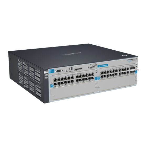
HPE 4200 vl Switch Series - Installation
Package contents
Installation precautions
Prepare the installation site
Install switch xl modules
Install second power supply (Optional)
Verify the switch passes self test
Mount the switch
Rack or cabinet mounting
Horizontal surface mounting
Wall Mounting
Connect the switch to a power source
Connect the network devices
Connect a console to the switch (Optional)
Hot swapping switch modules
Link to product related documents
Package contents
The 4200vl Switch series devices have the following components shipped withthem:
ProCurve Switch 4200vl Series Installation and Getting Started Guide
ProCurve Manager - CD ROM and booklet
Customer Support/Warranty booklet
Accessory kit 5065-6521 for the:
8-slot 4208vl Switch
4208vl-64GSwitch
4208vl-96 Switch
4208vl-72GS Switch
Accessory kit 5064-9943 for the:
4-slot 4204vl Switch
4202vl-48G Switch
4202vl-72 Switch
4204vl-48GS Switch
Each kit contains:
Two mounting brackets
Six 10 mm M4 screws to attach the mounting brackets to the switch
Four 5/8 in number 12-24 screws to attach the switch to a rack
Console cable
Power cord
top
Installation precautions
Follow these precautions when installing the 4200vl Switch Series devices:
WARNING:
Devices installed in a rack or cabinet should be mounted as lowas possible, with the heaviest device at the bottom and
progressively lighter devices installed above.The rack or cabinet should be adequately secured to prevent itfrom becoming
unstable and/or falling over.
HPE Support Center
HPE 4200 vl Switch Series - Installation
1/12
Advertisement
Table of Contents

Related Manuals for HP HPE 4200 Series


Summary of Contents for HP HPE 4200 Series
- Page 1 9/18/2020 HPE 4200 vl Switch Series - Installation HPE Support Center HPE 4200 vl Switch Series - Installation Package contents Installation precautions Prepare the installation site Install switch xl modules Install second power supply (Optional) Verify the switch passes self test Mount the switch Rack or cabinet mounting Horizontal surface mounting...
-
Page 2: Prepare The Installation Site
9/18/2020 HPE 4200 vl Switch Series - Installation Ensure a cover plate is installed on any empty switch power supply slot. A cover plate is required for safe operation, and to ensure proper switch cooling. To avoid energy and mechanical hazards, never allow any partof body, jewelry, tool, or other foreign object to enter any module or power supply slots. -
Page 3: Install Switch Xl Modules
9/18/2020 HPE 4200 vl Switch Series - Installation Port Type Cable Type Length Limits Copper cables Shielded twisted-pair cables complying withthe 802.3ak standard. 0.5 - 15 m CX4 NOTE: The Series 4200vl Switch devices are compatible with the IEEE 802.3ab standard including the Auto MDI/MDI-X feature,which allows use of either straight- through orcrossover twisted-pair cables for connecting to any network devices including end nodes,such as computers, or to other switches, hubs and routers. - Page 4 9/18/2020 HPE 4200 vl Switch Series - Installation Item Number Description Guides Low-force connector 2. The module is fully inserted when the module bulkhead is contacting,or very close to contacting the face of the switch. Figure 2: Tighten module retaining screws Item Number Description The module is fully inserted when the module bulkhead is contacting,or very close to contacting the face of the switch...
-
Page 5: Verify The Switch Passes Self Test
9/18/2020 HPE 4200 vl Switch Series - Installation 2. Once the power supply is installed, ensure user tighten the four retaining screws that hold it in place. The screws can be tightened with either a flat bladedor Torx T-10 screwdriver. Be careful not to overtighten the screws. Figure 4: Tighting the power supply retaining screws Item Number Description... -
Page 6: Mount The Switch
9/18/2020 HPE 4200 vl Switch Series - Installation Item Number Item Number Description Description Power socket NOTE: The 4200vl Switch Series does not have a power switch. They are powered onwhen the power cord is connected to the switch and to a power source.If installation requires a different power cord than the one supplied with the switch. 2. - Page 7 9/18/2020 HPE 4200 vl Switch Series - Installation Item Number Description 10 mm M4 screws Figure 7: Attaching brackets to a 5U chassis Item Number Description 10 mm M4 screws 2. Partially install a screw (5/8 in number 12-24) into the top hole of a pairof holes that are 0.5 in apart in each rack/cabinet upright as shownin the illustration below.
-
Page 8: Horizontal Surface Mounting
9/18/2020 HPE 4200 vl Switch Series - Installation Item Number Description Lower the switch withmounting brackets onto the partially installed screws,then tighten these screws 4. Install the other number 12-24 screw into the upper hole in each bracket. Tighten these screws. Figure 10: Installing the final rack mounting screw Item Number Description... -
Page 9: Connect The Switch To A Power Source
9/18/2020 HPE 4200 vl Switch Series - Installation The mounting brackets supplied with the switch allow user to mount it on awall. The illustrations below show mounting a 4208vl Switch. All other 4200vl Switches would be mounted in a similar way. CAUTION: For safe operation, do not install the switch with the vents or fans facing downward. -
Page 10: Connect The Network Devices
9/18/2020 HPE 4200 vl Switch Series - Installation Connect the network devices The type of network connections user will need to use depends on the typesof switch modules user have installed in 4200vl Switch Series. See the documentation accompanying the modules for cabling configurations andprocedures for those modules. In general for all the modules, when a network cable from an active network device is connected to the switch, the Link LED for the switch port should goon. -
Page 11: Telnet Console Access
9/18/2020 HPE 4200 vl Switch Series - Installation Item Number Description Console port Console cable suppliedwith the switch PC running a terminalemulator program, ora VT-100 terminal 1. Connect the PC orterminal to the switch’s Console Port using theconsole cable included with the Switch. (If PC or terminal has a 25- pin serial connector, first attach a 9-pin to 25-pin straight-through adapterat one end of the console cable.) 2. - Page 12 9/18/2020 HPE 4200 vl Switch Series - Installation Link to product related documents Click here to view a list of product related documents ©Copyright 2020 Hewlett Packard Enterprise Development LP Hewlett Packard Enterprise Development shall not be liable for technical or editorial errors or omissions contained herein. The information provided is provided "as is"...