
Related Manuals for Hanna Instruments HI9829


Summary of Contents for Hanna Instruments HI9829
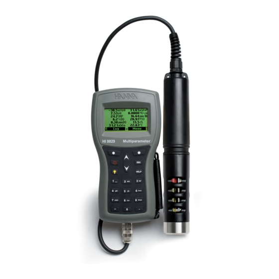
- Page 1 HI9829 Multiparameter Meter with Available GPS, Logging Probe, Turbidity & Ion Measurements...
- Page 2 If you need additional technical information, do not hesitate to e‑mail us at tech@hannainst.com or view our worldwide contact list at www.hannainst.com. All rights are reserved. Reproduction in whole or in part is prohibited without the written consent of the copyright owner, Hanna Instruments Inc., Woonsocket, Rhode Island, 02895, USA.
-
Page 3: Table Of Contents
CHAPTER 1- INTRODUCTION Preliminary Examination ..................... General Description ......................Display and Keypad Description ................... CHAPTER 2 - QUICK START Sensor and Probe Installation ....................Basic Operation ........................Help Function ........................CHAPTER 3 - SPECIFICATIONS System Specifications ......................Probe Specifications ......................Sensor Specifications ...................... - Page 4 Dissolved Oxygen Calibration ....................Conductivity Calibration ...................... Turbidity Calibration ......................Temperature Calibration ...................... Atmospheric Pressure Calibration ..................CHAPTER 8 - SYSTEM SETUP Meter Setup ........................Probe Setup ........................CHAPTER 9 - GPS MENU (optional) GPS Menu .......................... CHAPTER 10 - STATUS Meter Status ........................
- Page 5 Chapter 1 - INTRODUCTION Remove the instrument from the packing material and examine it carefully to make sure that no damage has occurred during shipping. If there is any damage, contact your local Hanna Instruments Office. Note: Save all packing materials until you are sure that the instrument functions correctly.
- Page 6 • Built‑in barometer for D.O. concentration compensation • Quick calibration feature • Measurement check to eliminate any erroneous readings GOOGLE™ is a registered trademark of Google, Inc. HANNA Instruments has no affiliation with Google™, Inc. iButton is a registered trademark of Maxim/Dallas Semiconductor Corp.
- Page 7 • Autorecognition of probe and sensors • Log‑on‑demand and automatic logging (up to 44,000 samples) on meter for all parameters • Graphical display of logged data • USB interface for PC communication • Auto‑ranging for EC, ISE and turbidity readings •...
- Page 8 Chapter 2 - QUICK START Before you begin using the HI9829 multiparameter system, either charge the included rechargeable C batteries for at least 6 hours or replace the rechargeable batteries with non‑rechargeable alkaline batteries. • Sensor O‑Rings must be lubricated with the supplied grease prior to installation.
- Page 10 The main operating modes for HI9829 are measurement, logging and setup. The measurement screen can be configured to display a single measurement or up to 12 simultaneous measurements by using the numbers 1‑7 on the keypad. Use the / keys to scroll through the measurements not being displayed.
- Page 11 Chapter 3 - SPECIFICATIONS TEMPERATURE ‑5.00 to 55.00 °C; Range 23.00 to 131.00 °F; 268.15 to 328.15 K Resolution 0.01 °C; 0.01 °F; 0.01 K Accuracy ± 0.15 °C; ± 0.27 °F; ±0.15 K Calibration Automatic at 1 custom point pH/mV Range 0.00 to 14.00 pH;...
- Page 12 CONDUCTIVITY Range 0 to 200 mS/cm (absolute EC up to 400 mS/cm) Manual: 1 µS/cm; 0.001 mS/cm; 0.01 mS/cm; 0.1 mS/cm; 1 mS/cm; Automatic: 1 µS/cm from 0 to 9999 µS/cm; 0.01 mS/cm from 10.00 to 99.99 mS/cm; Resolution 0.1 mS/cm from 100.0 to 400.0 mS/cm; Automatic (mS/cm): 0.001 mS/cm from 0.000 to 9.999 mS/cm;...
- Page 13 SALINITY Range 0.00 to 70.00 PSU Resolution 0.01 PSU Accuracy ±2% of reading or ±0.01 PSU whichever is greater Calibration One custom point SEAWATER SIGMA Range 0.0 to 50.0 σ σ σ Resolution 0.1 σ σ σ Accuracy ±1.0 σ σ...
- Page 14 Chloride Range 0.6 to 200.0 ppm Cl (as Cl ‑ 0.01 ppm to 1 ppm; Resolution 0.1 ppm to 200.0 ppm; Accuracy ±5 % of reading or 2 ppm, whichever is greater Calibration 1 or 2 point, 10 ppm and 100 ppm Nitrate-Nitrogen Range 0.62 to 200.0 ppm N (as NO...
- Page 15 METER SPECIFICATIONS Temperature Compensation Automatic from ‑5 to 55 °C (23 to 131 °F) 44,000 records (continuous logging or log‑on‑demand of all Logging Memory parameters) Logging Interval 1 second to 3 hours PC Interface USB (with HI929829 software) Waterproof Protection IP67 Environment 0 to 50 °C (32 to 122 °F);...
- Page 16 METER BATTERY LIFE The power consumption of the HI9829 multiparameter system is dependent on three things: 1. The measurement system configuration (probe type, sensor configuration) 2. The meter configuration (logging interval, GPS and backlight use) 3. The battery type (alkaline or rechargeable).
- Page 17 Non-logging Probe Logging Probe Sample Environment Fresh, brackish, seawater Waterproof protection IP68 Computer Interface USB PC (HI76982910) Internal Battery Type 1.5V Size AA Alkaline (4 pcs.) Typical Battery Life See below 140,000 measurements (single parameter logged) Memory 35,000 measurements (all parameters logged) Operating Temperature ‑5 to 55 °C * Storage Temperature...
- Page 18 LOGGING PROBE BATTERY LIFE All channels logging All channels logging Interval (no averaging) (10 sample averaging) 1 ‑ 5 sec 72 hours 72 hours 1 min 22 days 11 days 10 min 70 days 65 days HI7609829‑0 HI7609829‑1 HI7609829‑2 HI7609829‑3 Description pH/ORP Dissolved Oxygen...
- Page 19 HI7609829‑4 HI7609829‑10 HI7609829‑11 HI7609829‑12 Description EC/Turbidity Ammonium ISE Chloride ISE Nitrate ISE Measure Type Primary Unit 0 to 200.0 mS/cm 0.0 to 400 mS/cm Measure 0.02 to 200.0 ppm 0.6 to 200.0 ppm 0.6 to 200.0 ppm (absolute) Range as NH ‑N as NO ‑N...
-
Page 20: Chapter 4 - Probe Installation
Chapter 4 - PROBE INSTALLATION HI7609829 HI7629829 multisensor probes are used for the measurements of pH, ORP, conductivity, turbidity, dissolved oxygen, chloride, nitrate‑nitrogen, ammonium‑nitrogen and temperature. Each probe can utilize 3 sensors. A description of each sensor follows. HI7609829‑0 Combination pH sensor features a glass pH sensitive bulb and a silver/silver chloride double junction reference with gelled electrolyte. - Page 21 HI7609829‑10: Ammonium selective electrode (ISE) is a combination liquid membrane sensor used for the detection of free ammonium‑nitrogen in freshwater samples. The sensor utilizes a polymeric membrane made with ammonium ionophore in a PVC head and silver/silver chloride double junction gel filled reference electrode. This sensor is used in place of the pH sensor in the probe.
-
Page 22: Sensor Preparation/Activation
pH Preparation Remove the shipping cap from the pH sensor. If the shipping cap does not contain any liquid, pour HI70300 into shipping cap, place it back on the sensor and soak for at least 1/2 hour before use. HI70300 is not available, pH 4.01 buffer may be substituted. - Page 23 Hold the sensor at the connector and shake it down (like a mercury thermometer). Condition the sensor by soaking it in a small amount of HI9829‑12, 10 ppm Cl¯ standard for at least a 1/2 hour.
- Page 24 HI76x9829 can support 3 different sensors: Connector 1: pH, pH/ORP or ISE (Ammonium, Chloride, Nitrate), Connector 2: D.O., Connector 3: EC or EC/Turbidity. To make installation easier, the sensors have color‑coded caps and the sockets are identified with colored triangles. Note: The EC/Turbidity sensor with 9 pin connector does not have a color-coded cap.
- Page 25 For a correct installation: • Remove the syringe plunger; cut top off supplied sachet with silicone grease and empty contents into the syringe. Using the syringe, sparingly lubricate the O‑ring with a thin film of the sup‑ plied grease. Avoid getting any kind of grease or fingerprints onto the optical window. DO NOT SUBSTITUTE other grease/lubricants as it may cause the O‑Ring to swell.
-
Page 26: Chapter 5 - Initialization And Measurement
Chapter 5 - INITIALIZATION AND MEASUREMENT HI9829 is supplied with 4 rechargeable, size C NiMH (Nickel‑metal hydride) batteries. The battery symbol on the LCD indicates the remaining battery charge. The meter has a low battery warning, and when the symbol starts blinking, batteries should be charged or replaced with new ones. - Page 27 It takes about 6 hours to completely charge fully discharged batteries. Note: The meter log, GPS information, system setup and status can be viewed during battery charging. The battery charging status is indicated by a small animated battery icon found in the lower left corner. During charging the meter may feel quite warm. This is normal.
- Page 28 After connecting the desired sensors to the probe and connecting the probe to the meter (see previous chapter), turn the meter on by pressing ON/OFF. After the initialization has been completed, the meter displays the PROBE STATUS SCREEN. The probe status screen identifies the probe and attached sensors. Non‑logging probes are identified HI7609829 and logging probes are identified as HI7629829.
-
Page 29: Measurement Mode
Measurement mode is one of the three main operating modes of HI9829 (along with logging mode and setup mode). During measurement mode HI9829 will simultaneously measure data for all enabled parameters. • Use the numbers on the keyboard to select the number of parameters that are shown on the screen at one time. -
Page 31: Chapter 6 - Parameter Setup Menu
Chapter 6 - PARAMETER SETUP MENU From the main menu, use the / keys to highlight “Param‑ eter Setup” and then press <Select>. The following options will be displayed: Use the keys to scroll through the menu. Press the right softkey to enable or disable a single parameter, or the left softkey to enable or disable all parameters. - Page 32 Resistivity Unit The user can select resistivity from one of the following measurement units: Ω·cm, kΩ·cm or MΩ·cm. Resistivity is calculated from the conductivity measurement. The default unit is MΩ·cm. Seawater Sigma Unit This parameter is used for seawater analysis. It is calculated from the conductivity measurement and depends on water pressure, temperature and salinity.
- Page 33 Auto ppt: the meter automatically chooses the range to optimize the measurement, readings will be in ppt only. 1 ppm, 0.001 ppt, 0.01 ppt, 0.1 ppt or 1 ppt: the meter will display the measurement with selected resolution. The default value is Auto. GPS Format (optional) Global positioning coordinates have three standard formats: XX°XX’XX.X, XX°XX.XXX’...
-
Page 34: Averaging
Averaging is a software filter to minimize sensor noise and provide more stable readings. Averaging is particularly useful to get a representative reading of the “average” value from flowing water. Averaging will affect all measurements (except Turbidity which can be set separately). This value should be kept low if you want a fast response. -
Page 35: Chapter 7 - Calibration Mode
Chapter 7 - CALIBRATION MODE HI9829’s calibration routines are accessed by highlighting “Calibration” and pressing <Select> from the main menu. Calibration is the process that standardizes the electrical or optical signals from the sensors to reagent standards of known value. -
Page 36: Quick Calibration
The quick calibration method provides a quick single point calibration for pH, conductivity and dissolved oxygen sensors. HI9828‑0 calibration solution is used for both pH and conductivity. • Fill the calibration beaker 2/3 full with HI9828‑0 calibration solution. • Slowly place the sensors into the solution and dislodge bubbles that may adhere to the sensors. - Page 37 • Unscrew the calibration beaker and empty the solution. • Shake any remaining liquid off the probe and beaker. No droplets should remain on the D.O. sensor membrane. Note: Do not attempt to dry wipe the D.O. sensor as damage to the membrane may occur. •...
- Page 38 • Press <Measure> to return to the measurement screen. Custom buffer calibration • The HI9829 permits a single custom buffer to be used for pH calibration. This can be used along with standard buffers as part of a 2 or 3 point calibration or as a single point.
-
Page 39: Ph Calibration
Calibration Error Messages HI9829 displays a series of messages if an error has occurred during calibration. If the meter does not accept a pH calibration point, a short message is displayed to indicate the possible error source. The following screens are examples: These are the available messages: •... - Page 40 From the “Calibration” menu select “ Single param. calibration” and then “ISE” calibration. The display shows two options: “Calibrate ISE” and “Restore factory calib”. When an ISE replaces a pH sensor or another ISE model, previous calibrations need to be cleared using the <Restore factory calib.>...
- Page 41 Position the sachet to ensure sensor membrane and ceramic junction are completely immersed in solution. A value close to 100 ppm and the message “Not ready...” will be displayed. • When the reading is stable, the countdown timer will count down until the display shows the “Ready”...
-
Page 42: Orp Calibration
Preparation Accessories lists Hanna Instruments solutions used for ORP calibrations. The calibration should be conducted at temperatures between 20‑26 °C. The sensor should be clean and oil free. Procedure • From the “Calibration” menu select “Single param. calibration” and then “ORP” calibration. The display shows two options: “Custom ORP”... - Page 43 If the % D.O. saturation range is calibrated, the D.O. concen‑ tration range will also be calibrated, and vice versa. Dissolved oxygen concentration values are based on % D.O. saturation, temperature, salinity and atmospheric pressure. A standard solution or a reference D.O. meter may be used to compare readings during calibration.
- Page 44 Single point Custom % saturation calibration • For a calibration at another known value place sensor and temperature probe into the known solution and change the calibration value, press the <Cal. point> softkey and select the desired point. • To insert a different calibration value, press <Cal. point> and then <Custom>. Insert the desired value using the keypad, then press <Accept>.
- Page 45 • Select the “Conductivity” option and press <Select> to confirm. • Fill the calibration beaker with a conductivity standard (see Accessories for choosing the proper Hanna Instruments standard solution). • Pour additional standard into a second beaker to be used to rinse the sensor.
- Page 46 • Immerse the sensor into the rinse standard by raising and lowering the beaker a few times to ensure that the EC sensor channels are filled with fresh standard. • Place the calibration beaker over the EC sensor and dislodge any trapped bubbles. Screw the beaker into place.
- Page 47 • Note the temperature and adjust the conductivity value if needed. • Press <Confirm> to save the calibration. • After confirmation, the following messages are displayed: “Storing” and “Calibration completed”. • Press <OK> to return to the “Calibration” menu. • Press ESC twice to return to the main menu. •...
- Page 48 From the “Calibration” menu select “Single param. calibration” and then “Turbidity calibration”. The display shows two options: “Calibrate turbidity” and “Restore factory calib”. The Hanna Instruments turbidity sensor conforms to ISO 7027 standards which specifies the angle between the emitted and detected light and the light source wavelength. For best results perform a three point calibration at 0.0, 20.0 and 200.0 FNU.
- Page 49 Procedure Select “Calibrate turbidity” from the menu. The measured value is shown on the main part of the display, while the standard value appears on the secondary level. • The current turbidity value, the standard value and “Not ready...” are displayed and a stability timer counts down. •...
- Page 50 The probe is factory calibrated for temperature readings. The user can perform a single point temperature calibration or restore factory calibration. This procedure requires a reference temperature measuring instrument. • Select “Temperature” from the “Calibration” menu. • Select “Calibrate temperature”. •...
- Page 51 Place HI9829 in a wind‑free area and choose “Custom pressure” to perform a user calibration or “Restore factory calib”. Note: “Custom pressure” procedure requires a reference barometer. Select the “Atm. pressure” from the “Calibration” menu. • Select the “Custom pressure” option.
- Page 52 Chapter 8 - SYSTEM SETUP From the main menu, select “System setup” and then “Meter setup” or “Probe setup”. Note: If the password protection is enabled, you will be required to enter the password before any settings can be modified. Time The meter uses a real time clock for logging.
- Page 53 Auto Poweroff The Auto Poweroff function is used to save battery life. After the set time is elapsed, the meter will: 1. automatically switch off, if in normal measurement mode. Press On/Off to switch on again. 2. enter a sleeping mode, if the continuous logging mode is selected with a logging interval of at least 30 seconds.
- Page 54 <Accept> to store the identification. A maximum of 14 characters can be used. Language The language used in the meter user interface can be changed. The default language is English. Please contact your local Hanna Instruments Office for currently available languages.
- Page 55 Restore factory settings This function restores measurement settings to their original factory values. This includes measurement units, coefficients, other measurement configurations and all logged data. The factory calibration for the sensor channels is not affected. • Select the “Restore factory settings” and press <Select>. •...
- Page 56 Chapter 9 - GPS MENU (optional) HI9829 model featuring GPS (Global Positioning System) is provided with a built‑in 12 channel receiver and antenna to calculate meter position and track locations along with measurement data. The GPS has a position accuracy of 10 meters (30 ft).
- Page 57 Press <Info> to view the GPS coordinates of the selected location. Press <Delete> to erase the selected location. Press <New> to add a new location. Coordinates for a new location can be entered manually or by using the current GPS coordinates.
- Page 58 Chapter 10 - STATUS Useful information regarding the meter, probe (if connected) and GLP calibration data are available for viewing by selecting “Status” from the main menu. Select “Meter Status” to display information related to the battery, logging, internal temperature, password, Meter ID, serial number and firmware version.
- Page 59 • Press ESC to return to the “GLP” menu. Note: A “C” label near the buffer value indicates a custom point, while an “H” indicates a Hanna Instruments standard buffer value. If a quick calibration was performed, the buffer values are replaced with the “Quick calibration”...
- Page 60 • From the “GLP” menu, select the “ISE” option. • Data regarding the last ISE calibration will be displayed: standards used, sensor type, time and date of the calibration. • Use the / keys to scroll through the stored data for the last 5 calibrations. •...
- Page 61 Note: A “C” label near the calibration point indicates a custom point, while an “H” indicates a Hanna Instruments standard value. When the % D.O. range is calibrated, also the D.O. concentration range is calibrated, and vice versa. If no D.O. calibration has been performed or if calibration was cleared using the “Restore factory calib.”...
- Page 62 Note: If no turbidity calibration has been performed or if calibration was cleared using the “Restore factory calib.” option the offset and slope values are set to default, and the message ”Factory calibration” is displayed. Press <ESC> to return to the previous screen. Temperature •...
- Page 63 Chapter 11 - LOGGING MODE HI9829 HI76x9829 system offers many logging options that can be combined based on user needs. The following figures describe the available logging options.
- Page 65 From measurement mode, press <Log> to access the log menu. • The data logged on the meter are organized by lots. Up to 44,000 complete records can be stored in up to 100 lots. Each lot can store log‑on‑demand records and/or continuous records with different parameter configurations.
- Page 66 One Sample On Meter Use this option to log one set of enabled measurement parameters to the meter memory. • If there are no lots saved on the meter, press <New> to create a new lot. Use the keypad to enter the desired lot name and press <Accept>...
- Page 67 Continuous meter log • Select “Start meter log” to log the currently enabled parameters at the set logging interval on the meter. • To set the logging interval, highlight “Start meter log” and press <Options>. The log interval time can set from 1 second to 3 hours. Press <Modify>...
- Page 68 • All logged data can be viewed using two log recall options. The data logged on probe can be accessed only if the probe is connected to the meter or to the HI929829 PC application by using the “Probe log recall” option. The probe logs that have already been downloaded to the meter and the data logged on the meter can be viewed using the “Meter log recall”...
- Page 69 • Press <Data> to return to the previous screen or <Jump> to select a different sample in the same lot. When <Jump> is pressed, a text box appears to insert the desired sample number. • Press ESC to return to the menu. •...
- Page 70 • After <View> is pressed, the meter displays all data related to the selected lot: number of samples, memory space used, time and date of the first and the last readings. • To see all the sample details press <Download>. When the download is completed, the log is now stored on the meter and can be accessed from the ‘’Meter log recall’’...
- Page 71 • Press <Delete> to delete the selected remark from the meter. If the deleted remark is used in an existing lot, the information will be still available in the lot data. Delete all remarks • Select “Delete all remarks” to delete all remarks. The display will show the message “Do you want to perform the current operation?”.
- Page 72 • The tag information window will appear. Press <OK> to return to the previous screen or <Modify> to modify the tag ID. Note: If the typed SN is not stored in memory, the warning message “SN not found” will be displayed.
- Page 73 GPS tracking software such as Google™ Maps to view locations where measurements have been taken, therefore an internet connection is required to use this function. To allow our users access to the latest version of Hanna Instruments PC compatible software, we made http://software.hannainst.com...
- Page 74 Meter to PC data a. Select parameter units b. Select Meter from toolbar c. Select Lot d. Select Map...
- Page 75 • Connect the HI76982910 adapter to the probe and to a USB port on the PC. • Run the HI929829 application software. • To access the probe, press the “Probe” button from the toolbar on the top of the screen. •...
- Page 76 Probe Info Screen Lot Data Screen...
- Page 77 Chapter 13 - TROUBLESHOOTING/ERROR MESSAGES HI9829 displays error messages to aid in troubleshooting. Warnings are displayed for most issues, while Errors are displayed for critical issues. See the calibration chapter for messages that can occur during calibration. Other messages are listed below.
- Page 78 Replace the probe batteries. • ‘’User data corrupted!’’: This message appears when powering up the user data stored on meter are corrupted. Restart the meter. If the problem persists, contact your local Hanna Instruments Office.
- Page 79 • ‘’Warning x’’: Any other warning that appears at power‑on is identified using a numeric code. Restart the meter. If the problem persists, contact your local Hanna Instruments Office. Some meter/probe features can be accessed but with no guarantee. • ‘’Errors x’’: Any critical errors that appear are identified using a numeric code, and the meter is...
- Page 80 HI7698292 probe maintenance kit includes HI7042S (electrolyte solution for D.O. sensor), spare membranes with O‑Rings for D.O. sensor, a small brush for cleaning EC , O‑Rings for sensor connectors, 6 g sachet with silicone grease to lubricate the O‑Rings and syringe. General Maintenance •...
- Page 81 D.O. Sensor Maintenance For a top performance probe, it is recommended to replace the membrane every 2 months and the electrolyte monthly. Proceed as follows: • Unscrew the membrane by turning it counterclockwise. • Rinse a spare membrane with some electrolyte while shaking it gently. Refill with clean electrolyte. •...
- Page 82 If dark deposits appear on the frosted surface, move the paper slightly. Continue polishing until you are satisfied with the surface. Rinse sensor with water. The Hanna Instruments HI76X9829 has been designed for a variety of water quality measurements both in situ or in active deployments in urban or natural waters.
- Page 83 It is suitable for deployment in open waters; monitoring lakes, ponds, wetland basin, infiltration basins, bays. Schedule regular service to remove aquatic weed growth that may be interfering with representative water samples. The probe is suitable for measurements in a flow cell. Pumping water to a flow‑through monitoring station has obvious pros and cons.
- Page 84 This Appendix describes additional information about the ISE sensors used on the HI76x9829 Probe. HI7609829‑10: Ammonium selective electrode (ISE) is a combination liquid membrane sensor used for the detection of free ammonium‑nitrogen in freshwater samples. The sensor utilizes a polymeric membrane made with ammonium ionophore in a PVC head and silver/silver chloride double junction gel filled reference electrode.
- Page 85 The calibration solutions and displayed measurements are as ppm Ammonium‑ nitrogen. Due to the space restriction of the display the unit of measurement will be displayed as “ppmAm”. The ammonium sensor will last longer in colder clean waters than in severely contaminated water or warmer waters.
- Page 86 HI7609829‑11: Chloride ion selective electrode is a combination solid state sensor used for the detection of free chloride ions in freshwater samples. The sensor utilizes a silver chloride pellet housed in a PEI head and a silver/silver chloride double junction gel filled reference electrode. The outer body of the sensor is the thermoplastic PEI.
- Page 87 The calibration solutions and displayed measurements are as ppm Chloride ions. Due to the space restriction of the display the unit of measurement will be displayed as “ppmCl” (without charge). The chloride sensor will last longer in colder clean waters than in severely contaminated water or warmer waters.
- Page 88 The sensor responds in a Nernstian manner (like a pH sensor) and produces a voltage that the meter converts to a concentration value. The calibration solutions and displayed measurements are as ppm Nitrate ‑ nitrogen. Due to the space restriction of the display the unit of measurement will be displayed as “ppmNi”. The nitrate sensor will last longer in colder clean waters than in severely contaminated water or warmer waters.
- Page 89 (5 pcs.), HI7698290 calibration beaker, ® HI9828‑25 calibration solution (500 mL), HI7698291 USB cables, HI710046 Cigarette Lighter Cable, Manual, appropriate probe shield and specified sensors) HI9829 meter, probe with 4 meter (13.1’) cable, with pH/ORP, EC, D.O. HI9829-00041 sensors and 115 Vac adapter. HI9829-00042 Same as HI9829‑00041 with 230 Vac adapter.
- Page 90 HI9829-10041 EC, D.O. sensors and 115 Vac adapter. HI9829-10042 Same as HI9829‑10041 with 230 Vac adapter. HI9829 meter with GPS, Probe with 10 meter (33’) cable, with pH/ORP, EC, HI 9829-10101 D.O. sensors and 115 Vac adapter. HI9829-10102 Same as HI9829‑10101 with 230 Vac adapter.
- Page 91 HI9829-12041 pH/ORP, EC, D.O. sensors and 115 Vac adapter. HI9829-12042 Same as HI9829‑12041 with 230 Vac adapter. HI9829 meter with GPS, Logging Probe with 10 meter (33’) cable, with pH/ HI9829-12101 ORP, EC, D.O. sensors and 115 Vac adapter. HI9829-12102 Same as HI9829‑12101 with 230 Vac adapter.
- Page 92 230 Vac/12 Vdc adapter, UK plug 230 Vac/12 Vdc adapter, South African plug HI710013 HI710014 230 Vac/12 Vdc adapter, Australian plug HI710140 Hard carrying case for HI9829 QUICK CALIBRATION SOLUTIONS HI9828-25 Quick calibration solution, 500 mL HI9828-27 Quick calibration solution, 1 gal.
- Page 93 HI7035L 111800 µS/cm calibration solution, 500 mL HI7039L 5000 µS/cm calibration solution, 500 mL TURBIDITY SOLUTIONS HI9829-16 0 FNU turbidity calibration solution, 230 mL HI9829-17 20 FNU turbidity calibration solution, 230 mL HI9829-18 200 FNU turbidity calibration solution, 230 mL...
- Page 94 100 ppm nitrate (as N) standard for HI7609829‑12, 25 x 20 mL sachet CERTIFICATION All Hanna Instruments conform to the CE European Directives. Disposal of Electrical & Electronic Equipment. The product should not be treated as household waste. Instead hand it over to the appropriate collection point for the recycling of electrical and electronic equipment which will conserve natural resources.
- Page 95 Returned Goods Authorization (RGA) number from the Technical Service department and then send it with shipping costs prepaid. When shipping any instrument, make sure it is properly packed for complete protection. Hanna Instruments reserves the right to modify the design, construction or appearance of its products without advance notice.
- Page 96 World Headquarters Hanna Instruments Inc. Highland Industrial Park 584 Park East Drive Woonsocket, RI 02895 USA www.hannainst.com MAN9829 Printed in ROMANIA...