
Related Manuals for Siemens 3TM


Summary of Contents for Siemens 3TM
- Page 1 Vacuum contactor 7.2 kV – 15 kV, 3-pole 4.15 kV – 6.9 kV, 1-pole OPERATING INSTRUCTIONS Order No.: 9229 0106 176 0- Version: 07.2020 en © Siemens AG 2020. All rights reserved.
-
Page 2: Service
Service Siemens Service contact persons can be found under: Customer service • Telephone: +49 180/524 7000 • Fax: +49 180/524 2471 • on the internet under web address www.siemens.com/energy-support • by email: support.energy@siemens.com or from any local Siemens representative. 9229 0106 176 0-... -
Page 3: Table Of Contents
Contents Service ................................2 List of abbreviations ............................4 Other applicable supplements for Operating Instructions 9229 0106 ..............4 For your safety ..............................5 Signal terms and definitions ..........................5 Manufacturer’s product liability ........................... 6 General safety instructions ..........................6 Type approval according to the Radiation Protection Act (formerly German X-Ray Ordinance) ...... -
Page 4: List Of Abbreviations
List of abbreviations ANCE Asociación de Normalización y Certificación, A.C. (Association for Standardisation and Certification) ANSI American National Standard Institute American Wire Gauge BGBl Bundesgesetzblatt (German Federal Law Gazette) Close-Open Canadian Standards Association Deutsches Institut für Normung (German Institute for Standardisation) Dual in-line package DNV GL Det Norske Veritas AS (DNV) and Germanischer Lloyd SE (GL) -
Page 5: For Your Safety
For your safety For your safety The operating instructions are an integral part of the switching device and contain all information for commissioning and use. The operating instructions must be read completely, the instructions contained must be followed and the warnings must be observed. Smooth and safe operation of this switching device requires proper transport and storage, professional installation and assembly, as well as careful operation and maintenance. -
Page 6: Manufacturer's Product Liability
• Parts have been incorrectly fitted or adjusted. • Settings have not been made in accordance with Siemens specifications. • After installation and adjustment, no final test is performed with a test unit approved by Siemens including documentation of the test results. - Page 7 For your safety Ventilation of the installation space Note Inadequate ventilation leads to material damage. The customer is to ensure there is adequate ventilation in the installation space or in the switch cabinet (see “Installation site”, p. 17). Subsequent attachments and fittings Note In the event of subsequent attachments or fittings, e.
-
Page 8: Type Approval According To The Radiation Protection Act (Formerly German X-Ray Ordinance)
For your safety Type approval according to the Radiation Protection Act (for- merly German X-Ray Ordinance) Parasitic X-ray emitters The vacuum interrupters installed in the switching devices are type-approved as par- asitic X-ray emitters according to Section 45 of the Radiation Protection Act of the Federal Republic of Germany and they comply with the requirements for parasitic X- ray emitters according to Section 23 of the current Radiation Protection Ordinance up to the rated voltage defined in the approval certificate. -
Page 9: Transport/Storage/Packaging
Major damage must be documented photographically. • Ensure that any damage to the transport unit is confirmed by the transport com- pany in writing. Scope of delivery Delivery includes: • 3TM vacuum contactor • Operating instructions • Connector (accessory pack) Unpacking Working materials Required tools: Knife/scissors. -
Page 10: Reuse Of Transport Unit
Transport/storage/packaging Fig. 1 3TM 3-pole Transporting the vacuum contac- Fig. 2 3TM 1-pole Transporting the vacuum contac- Due to the low weight, no lifting eyes are provided. The vacuum contactor can be lifted and transported without tools. The fastening eyelets (*) can be used for lifting with a crane. Watch for shifting... -
Page 11: Storage
Transport/storage/packaging Storage Note During transport and storage, the vacuum contactor must be in the following con- dition: • OPEN switch position • Unlatched condition (only if unlatching is available). Note Risk of corrosion damage if stored improperly! The vacuum contactor can be stored for up to a year in its transport unit if the stor- age conditions listed below are met. - Page 12 Transport/storage/packaging Blank page 9229 0106 176 0- 2020-09-18...
-
Page 13: General Information
The operating instructions are an integral part of the switching device and contain all information for commissioning and use. The basic version and all listed configurations of the vacuum contactors 3TM are type-tested devices as per IEC 62271-106 (see also “Standards” on page 13) - Page 14 General information • GOST R 52565-2006 Alternating-current circuit-breakers for voltages from 3 to 750 kV. General specifica- tions • GOST 1516.3-96 Electrical equipment for AC voltages from 1 to 750 kV. Requirements for dielectric strength of insulation • UL 347 Medium-Voltage AC Contactors, Controllers, and Control Centers •...
-
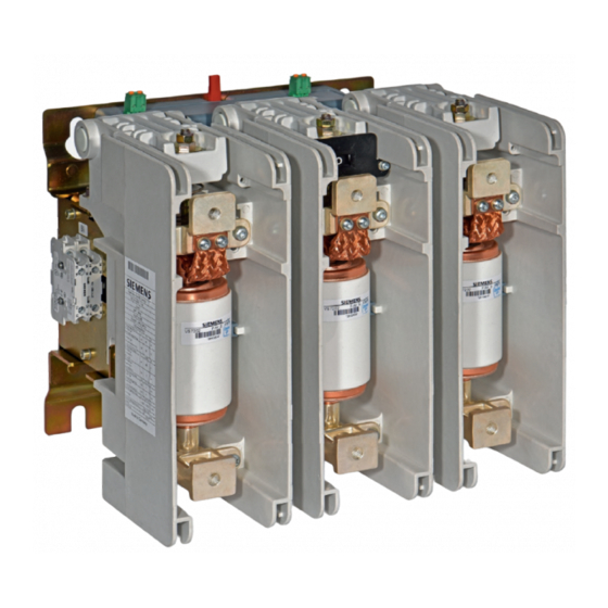
Page 15: Description
Description Description Design The vacuum contactor is a 1-pole or 3-pole switching device consisting of: • the high-voltage part, with a vacuum interrupter or three vacuum interrupters, customer terminals and switching position indicator on the front • the low-voltage section with the solenoid actuator •... - Page 16 Description Fig. 5 Front view – high-voltage side, 1-pole Fig. 6 Rear view – mounting side, 1-pole Base plate (mounting) Unlatching (EMERGENCY STOP), manual (optional) Vacuum interrupter Draw bar for manual unlatching (optional) Upper terminal Cover of the manual unlatching Lower terminal Connector for supply voltage A1/A2 Position indicator (CLOSED –...
- Page 17 The vacuum inter- rupters work synchronously in the same direction. The solenoid actuator and the shunt release of the vacuum contactor 3TM can be actuated with AC or DC. Vacuum contactors 3TM work according to a defined closing and opening time, which can be configured and extended by an additional closing and opening delay.
- Page 18 Description Fig. 9 Terminals A1/A2 and optionally E1/E2 of the electronic controller The electronic controller also allows the configuration of additional closing and open- ing delays. If no configuration is selected, only the natural closing and opening time of the switching device is active. The configuration is delivered ex works according to the option ordered.
-
Page 19: Name Plate
Mechanical strain, values given for vibrations and shock Mechanical stress Weight y Weight Date of manufacture 08/18 z Date of manufacture Made in Germany Fig. 12 Example – rating plate for vacuum contactor 3TM, 3-pole 9229 0106 176 0- 2020-09-18... -
Page 20: Technical Data
Description Technical data 1-pole 3-pole Electrical data Rated voltage U (phase-to-phase) Rated voltage U (phase-to-earth) 4.15 – – – – – Rated frequency f 50-60 Rated lightning impulse withstand voltage Rated short-duration power frequency withstand volt- 28** age U Rated operating current I (at ambient temperatures ranging from -40 °C to +70 °C) Thermal current I... - Page 21 Description 1-pole 3-pole Mechanical data 12/13 14/15 32/33 34/35 Maximum mechanical switching frequency, without ops/h 1 200 latching and unlatching with latching and unlatching ops/h Mechanical service life, without latching and unlatching in an ambient temperature range from -5 °C to +55 °C 100 000 1 million from +55 °C to +70 °C...
-
Page 22: Ambient Conditions
Description Ambient conditions Vacuum contactors are suitable for use in the fol- lowing climate classes according to IEC 60721-3- 3:2019: +70 °C Class • Climatic ambient conditions: 3K22 3K22 -40 °C • Biological ambient conditions: • Mechanical ambient conditions: 3M11 •... -
Page 23: Installation Altitudes
The installation altitude for the vacuum contactor is set at the factory according to the ordering option. As standard, 3TM vacuum contactors can be used at -1250 m to +2000 m. For high- er operation heights, a configuration from 2000 m to 5000 m can be ordered. -
Page 24: Dimension Drawings
Distance of the mounting holes Width of the base plate Threads in the upper and lower terminals Mass 20 – 25 23 – 25 Fig. 22 Rated data of 3TM vacuum contactor, with auxiliary switches 4NO + 4NC 9229 0106 176 0- 2020-09-18... - Page 25 Distance of the mounting holes Width of the base plate Threads in the upper and lower terminals Mass 20 – 25 23 – 25 Fig. 25 Rated data of 3TM vacuum contactor, with auxiliary switches 6NO + 6NC 9229 0106 176 0- 2020-09-18...
- Page 26 Description Blank page 9229 0106 176 0- 2020-09-18...
-
Page 27: Circuit Diagrams
Circuit diagrams 24 V to 32 V DC and 110 V to 125 V AC/DC Colours of insulating sleeves of connector plugs -X7.1 red -X7.2 yellow -X5.1 black -X5.2 white Fig. 26 Circuit diagram for 24 V to 32 V DC and 110 V to 125 V AC/DC *if available 9229 0106 176 0- 2020-09-18... - Page 28 48 V to 60 V DC and 220 V to 250 V AC/DC Colours of insulating sleeves of connector plugs -X7.1 red -X6.1 black -X6.2 yellow -X5.2 white Fig. 27 Circuit diagram for 48 V to 60 V DC and 220 V to 250 V AC/DC * if available 9229 0106 176 0- 2020-09-18...
-
Page 29: Installation
Attach the vacuum contactor by the specified mounting points without shear, ten- sile, or compressive stresses. Due to the special shape of the mounting holes on the 3TM vacuum contactor , it is possible to position it safely on loose, pre-assembled screws. - Page 30 Installation Earthing Connect the earthing conductor on the earthing terminal (22) to the high-voltage pro- tective earth as specified (DIN EN 50341). Note The base plate is provided with a protective layer. The earthing conductor must be connected on the customer’s premises with the use of a contact washer: •...
- Page 31 Installation Removing the auxiliary • Press down the upper and lower pressure surfaces (1) at the same time and flip switch up auxiliary switch (23) and remove it towards the front (2) (see Fig. 31). • Both auxiliary switches can also be removed at the same time. Fig.
- Page 32 Installation Calculating the connection In the case of long supply lines for the control circuit, malfunctions may occur on wire these supply lines when switching on, due to too high voltage drops. As a yardstick, the maximum length of the connection wire can be calculated accord- ing to: L = 0.004 x U2 x A Here,...
- Page 33 Installation Functional check with When low voltage is applied, the release, closing, and opening of the vacuum con- applied low voltage tactor can be checked. DANGER Danger to life – high voltage! Closing without safety precautions can result in death or serious injury. Test the vacuum contactor in the switchbay with high voltage applied only after faultless functioning has been ascertained (see “Commissioning”, p.
- Page 34 Installation Preparing the contact surfaces Note Clean silver-plated contact areas with a cloth; do not brush. Different connection materials (AI/Cu) must not be cleaned with the same clean- ing tools. Silver-plated parts must not be bolted to aluminium bars! Use a steel brush to carefully brush (cross-wise) the contact surfaces of the cable lugs or conductor bars until they are metallic bright and wipe off any residue using a clean cloth.
- Page 35 Installation Mounting conductor bars Adjust the conductor bars in such a way that, before fastening, they lie flat easily and fit the holes on the contact surfaces of the upper and lower terminal. Fig. 40 Conductor bars mounted at an angle Fig.
- Page 36 Installation Blank page 9229 0106 176 0- 2020-09-18...
-
Page 37: Operation
Operation Operation DANGER Danger to life due to electric shock! Electric shock can result in death, serious injury, or considerable material dam- age. • Do not touch live parts! • Ensure that the vacuum contactor is operated only by qualified personnel who are familiar with the operating instructions and observe the warning notices! •... -
Page 38: Troubleshooting
WARNING Do not commission the vacuum contactor if there are malfunctions. If the malfunctions or damage cannot be remedied, contact a sales representative or Siemens Service and, if necessary, send back the vacuum contactor in the original packaging. Troubleshooting Incident... -
Page 39: Maintenance
Measurement of conductance of auxiliary switch contacts. Checking the switching Reliable switching of the 3TM vacuum contactor is only ensured if the switching stroke of vacuum stroke of the vacuum interrupters is not below the minimum of 3.5 mm and does not interrupters exceed the maximum of 7.5 mm. - Page 40 Maintenance Limit Fig. 42 OPEN switch position Fig. 43 CLOSED switch position Limit: a - b = min. 3.5 mm or max. 7.5 mm OPEN switch position CLOSED switch position Adjusting the switching Torsional loading of the draw bar (40) of the vacuum interrupters (3) must be pre- stroke of vacuum vented.
- Page 41 Maintenance If the value is below the limit - turn the adjusting nut (42) clockwise at least one turn, approx. 1.5 mm lower. A complete turn corresponds to approx. 1.25 mm. If the value is above the limit – turn the adjusting nut (42) counter-clockwise at least one turn, approx.
-
Page 42: Accessories And Spare Parts
Maintenance Accessories and spare parts Replacing spare parts To ensure that the device operates reliably, spare parts must be replaced only by qualified personnel. CAUTION Risk of injury! Put the vacuum contactor in the OPEN position. Operate the manual unlatching if available. - Page 43 Maintenance Reconfiguring the electronic controller The supply voltage can be reconfigured by switching over the DIP switch S2 (26) and reconnecting the coloured flat connectors to X5/X6/X7: • 110 V – 125 V AC/DC <> 220 V – 250 V AC/DC •...
- Page 44 Maintenance Positioning of connectors with colour codes -X5.2 -X5.2 -X5.1 -X6.2 -X6.1 -X7.2 -X7.1 -X7.1 Fig. 48 Positioning of connectors with colour code at Fig. 49 Positioning of connectors with colour code for 48 V – 60 V DC and 220 V – 250 V AC/DC parallel connection 24 V –...
- Page 45 Maintenance Configuration of supply Using the DIP switches S2 (26) and the set-up matrix, have the customer adjust the voltage U of the electronic settings on the electronic controller. controller 110 V–125 V AC/DC, 24 V–32 V DC and 220 V–250 V DC, 48 V–60 V DC 230 V–240 V AC OPEN...
- Page 46 Maintenance Electronic controller Cover hood of the electronic controller 0.6 x 3.5 DIP switch S2 6 ± 0.5 Nm Fig. 51 Mount cover – example, 3-pole Mounting the cover Tool: Flat-head screwdriver size 0.6 x 3.5 for the connectors and Hexagon spanner size 4 for the cover •...
-
Page 47: Manufacturer's Product Liability
If the packaging is no longer needed, it can be fully recycled. Hazardous substances When delivered by Siemens, the product does not contain any hazardous substanc- es within the scope of the Hazardous Substances Ordnance applicable to the terri- tory of the Federal Republic of Germany. The switching devices are free from asbestos, halogens, and lead. - Page 48 Maintenance Blank page 9229 0106 176 0- 2020-09-18...
-
Page 49: Index
Index Index – Altitude correction factor ........23 Name plate ........... 15 Ambient conditions ..........22 Ambient temperature range ........21 Opening delay ............17 Areas of application ..........13 Opening time ............17 – Auxiliary switch ......15 – Operating mechanism lever ...... - Page 50 Index Blank page 9229 0106 176 0- 2020-09-18...
-
Page 51: Central Legend
Central legend Central legend 1 Vacuum contactor 2 Base plate 3 Vacuum interrupter 4 Upper terminal 5 Lower terminal 6 Position indicator OPEN-CLOSED 7 Pole shell 8 Name plate 9 Mechanical closing latching with shunt release Y1 10 Cover of closing latching 11 Shunt release Y1 12 Push rod for manual unlatching 13 Coupling point for customer connection... - Page 52 Published by Siemens AG Smart Infrastructure Distribution Systems Schaltwerk Berlin Nonnendammallee 104 13629 Berlin Germany...