
Related Manuals for York J Series


Summary of Contents for York J Series
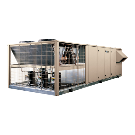
- Page 1 MILLENNIUM PACKAGED ROOFTOP OPTILOGIC CONTROL SUPPLEMENT R410A ONLY, GEN3 INSTALLATION, OPERATION & MAINTENANCE New Release Form 100.50-NOM7 (808) P/N 417631-A 25 THROUGH 40 TONS "J" SERIES, R410A...
- Page 2 FORM 100.50-NOM7 (808) IMPORTANT! READ BEFORE PROCEEDING! GENERAL SAFETY GUIDELINES This equipment is a relatively complicated apparatus. which it is situated, as well as severe personal injury or During installation, operation, maintenance or service, death to themselves and people at the site. individuals may be exposed to certain components or conditions including, but not limited to: refrigerants, This document is intended for use by owner-authorized...
- Page 3 FORM 100.50-NOM7 (808) CHANGEABILITY OF THIS DOCUMENT In complying with YORK policy for continuous prod- It is the responsibility of operating/service personnel to uct improvement, the information contained in this verify the applicability of these documents to the equip- document is subject to change without notice. While ment in question.
-
Page 4: Nomenclature
FORM 100.50-NOM7 (808) JOHNSON CONTROLS... -
Page 5: Table Of Contents
FORM 100.50-NOM7 (808) TABLE OF CONTENTS Nomenclature ...............................4 Table Of Contents ............................5 List Of Figures ..............................7 List Of Tables..............................8 Acronym Chart .............................8 SECTION 1 – INSTALLATION ......................9 General ................................9 Field Wiring ..............................9 SECTION 2 – START-UP .........................14 Checking The System Prior To Initial Start (No Power)................14 Unit Checks –... - Page 6 FORM 100.50-NOM7 (808) SECTION 5 – PARAMETER DESCRIPTIONS AND OPTIONS ...........52 Parameter Description And Options (Setpoints) ..................52 Status Key Parameters ..........................52 Setpoint Key Parameters ..........................52 Unit Setup Key Parameters ........................53 Configuration Key Parameters .........................58 Service Key Parameters ..........................59 Changing “Setpoints” ..........................60 Passwords ..............................61 SECTION 6 –...
-
Page 7: List Of Figures
FORM 100.50-NOM7 (808) LIST OF FIGURES FIG. 1 – FIELD CONTROL WIRING ....................11 FIG. 2 – OPTILOGIC CONTROL PANEL ..................12 FIG. 3 - TRAP DETAIL FOR DRAW THROUGH APPLICATION ..........14 FIG. 4 – CV SPACE SENSOR COOLING ALGORITHM - ECONOMIZER NOT SUITABLE ..21 FIG. -
Page 8: List Of Tables
W2 Thermostat Input For The Second Stage of Heating OA Outdoor Air X Alarm Output Y1 Thermostat Input For The First Stage of Cooling OAD Outside Air Damper OAT Outside Air Temperature Y2 Thermostat Input For The Second Stage of Cooling YDC YORK Digital Controller JOHNSON CONTROLS... -
Page 9: Section 1 - Installation
Shielded wire, notifies the user of a problem. If desired, YORK ser- grounded at the control box only, must be used. vice can provide remote monitoring and automatically... - Page 10 Installation FORM 100.50-NOM7 (808) This state is maintained until the input is deactivated VAV Heat Relay Output (contacts open). This is a field wired OUTPUT that is used to command Contacts Closed = Smoke Purge Operation the VAV boxes to full open during heating mode and Contacts Open = Normal Operation.
-
Page 11: Fig. 1 - Field Control Wiring
FORM 100.50-NOM7 (808) CTB3 FIELD CONTROL WIRING CTB3 FIELD CONTROL WIRING CTB3 9 10 11 12 14 15 16 17 19 20 21 22 23 25 26 27 7 Wire Thermostat COMMON R (24VAC) Y1 (Cool Stage 1) Y2 (Cool Stage 2) W1 (Heat Stage 1) W2 (Heat Stage 2) G (Fan) -
Page 12: Fig. 2 - Optilogic Control Panel
Installation FORM 100.50-NOM7 (808) CTB3 FLEXSYS WIRING CTB3 FlexSys Evap Temperature Reset Input: FlexSys UnderFloor Slab Temperature Sensor: This is used to initiate reset of the SAT if enabled. The FlexSys Under-Floor Slab Temperature sensor is located on the concrete slab, which makes up the FlexSys Bypass Filter Dirty Filter Switch Input: bottom of the Under-Floor plenum, and measures the temperature of this slab. - Page 13 FORM 100.50-NOM7 (808) Static Pressure Control Plastic Tubing Static Pressure Probe Installation (Pneumatic Tubing) On units with duct static transducers (VAV units) and Duct static transducers (all VAV and FLEXSYS units) any unit with an optional building pressure, a Static and any unit with an optional building pressure control Pressure Probe must be field installed at the top of the transducer, require pneumatic tubing to be field sup-...
-
Page 14: Section 2 - Start-Up
VAV units and/or for purge operation must be installed and serviced by an (as applicable - refer to Installation section of authorized YORK service mechanic or manual). a qualified service person experienced 10. Verify all applicable pneumatic tubing has been field... -
Page 15: Unit Checks - Power Applied
FORM 100.50-NOM7 (808) 17. If applicable, verify installation of air filters (refer GAS HEAT MODELS "STAGED" to Installation section for size and quantity). Pre-Start Checks: 18. Verify Variable Frequency Drive setpoints for VAV units and optional Variable Frequency Drive Ex- •... -
Page 16: Gas Heat Models "Modulating
Start-up FORM 100.50-NOM7 (808) • The control will also restart the process if the GAS HEAT MODELS "MODULATING" Not available. rollout switch(s) (2 switches, located above the burners) opened and have been reset, indi- cating burning inside the burners and/or outside of the heat exchanger tubing. -
Page 17: Section 3 - Sequence Of Operation
FORM 100.50-NOM7 (808) SECTION 3 – SEQUENCE OF OPERATION COMPRESSOR STAGING Constant Volume and Variable Air Volume stage com- pressors as follows: TABLE 1 - 25 – 40-TON R410A COMPRESSOR LOGIC Note that ASCD (anti short cycle delay) and Minimum Compressor Logic Constant Volume Run Time will take priority above Compressor total-... -
Page 18: Compressor Average Run Times
Unit Sequence of Operation FORM 100.50-NOM7 (808) CV Operation COMPRESSOR AVERAGE RUN TIMES For CV operation: To increase system reliability, all compressors will be • The Supply Fan will be ON whenever the G input staged up (ON) based on average run time. The com- from the Thermostat is present. -
Page 19: Timeouts And Delays
FORM 100.50-NOM7 (808) TIMEOUTS AND DELAYS Table 2 lists the timeouts and delays that are to apply in all functions unless an exception for a specific function is specified. TABLE 2 – TIMEOUTS AND DELAYS Number Timeout or Delay Description ASCD for cooling This “minimum OFF time”... - Page 20 Unit Sequence of Operation FORM 100.50-NOM7 (808) As the Heating Stages are de-energized, or if steps of For this option to function, the configuration setting heat should be dropped due to Excessive SAT (supply Space Sensor Enable must be set to ON and the sensor air temperature), the steps of heat will be de-energized must be reliable.
-
Page 21: Fig. 4 - Cv Space Sensor Cooling Algorithm - Economizer Not Suitable
FORM 100.50-NOM7 (808) Cooling Operation with a Space Sensor Control Algorithm For Space Sensor Cooling - Economizer Suitable For cooling operation, the space temperature will be controlled to either the: In CV cooling operation with a space sensor and when free cooling is available (“economizer suitable”), the •... -
Page 22: Fig. 6 - Cv Space Sensor Stepped Heat Algorithm
Unit Sequence of Operation FORM 100.50-NOM7 (808) Heating Operation With a Space Sensor • PI gain values are to be determined by such that all heating steps are on within 20 minutes with a 10°F For Heating operation, the space temperature will be space temperature error. -
Page 23: Table 3 - Modes Of Operation
FORM 100.50-NOM7 (808) TABLE 3 – MODES OF OPERATION Heating Cooling Control Occupied Unoccupied Occupied Unoccupied Controller Occupied input is Thermostat Controller Occupied input Controller Occupied input Controller Occupied input is ON OFF (deenergized by ‘stat is ON (energized by ‘stat is OFF (deenergized by (energized by ‘stat occ. -
Page 24: Variable Air Volume Sequence Of Operation
Unit Sequence of Operation FORM 100.50-NOM7 (808) • Controlled to maintain the Duct Static Pressure VARIABLE AIR VOLUME SEQUENCE OF OPERATION setpoint when cooling is ON. • ON and controlled for heating or cooling when Under Variable Air Volume Operation, the unit will be the Thermostat G output is ON. -
Page 25: Fig. 8 - Vav Occupied Heating To Maintain Rat And Morning Warm Up
FORM 100.50-NOM7 (808) • The programmable parameter VAV Occupied Heat- • The programmable parameter VAV Occupied Heat- ing must be set to ON to enable the Occupied Heat- ing must be set to ON to enable the Occupied Heat- ing With A Space Sensor function. ing With A Space Sensor function. -
Page 26: Fig. 10 - Vav Unoccupied Cooling Temperature Control
Unit Sequence of Operation FORM 100.50-NOM7 (808) • Non-Economizer Operation or Economizer Opera- COOLING DESTAGING COOLING STAGED ON tion when economizer is not suitable is as described in Figure 12. COOLING ON The setpoint is as determined for the space temperature condition and is either the VAV Cooling High Tem- perature Setpoint or the VAV Cooling Low Temperature Setpoint. -
Page 27: Fig. 12 - Occupied Heating And Cooling Setpoint Selection Algorithm
FORM 100.50-NOM7 (808) • The transition from cooling to occupied heating The Morning Warm Up start time will be 60 minutes occurs at 2°F below the “VAV Setpoint for SAT prior to scheduled occupancy, or BAS initiates the reset”. morning warm-up. •... -
Page 28: Table 4 - Vav Modes Of Operation
Unit Sequence of Operation FORM 100.50-NOM7 (808) TABLE 4 – VAV MODES OF OPERATION Heating Cooling Control Occupied Unoccupied Occupied Unoccupied ‘stat uses its programmed Same as occupied heat- ‘stat uses its programmed oc- Same as occupied cooling, Thermostat occupied htg. Setpoint, ing, except ‘stat uses its cupied clg. -
Page 29: Economizer Operation
FORM 100.50-NOM7 (808) ECONOMIZER OPERATION Outside Enthalpy Method: Economizer will be suitable when OA Enthalpy < Economizer operation is described in the following Outside Enthalpy Number parameter value and OAT < sections. A final section within Economizer operation (SAT setpoint + 10°F). A 2°F hysteresis about the (SAT description is on Economizer Loading. -
Page 30: Ventilation Option Operation
Unit Sequence of Operation FORM 100.50-NOM7 (808) Control of Compressors with Economizer Cooling Lockout on OAT parameter value while the call for several compressors exists, the compressors in this In Economizer Operation, compressors are started only case (and only in this case) will turn ON simultaneously. when the specified SAT setpoint can not be achieved This is considered acceptable, as this situation is not through outside air and return air mixing. -
Page 31: Fig. 13 - Oad Minimum Position Reset
FORM 100.50-NOM7 (808) Sensor 100% If all conditions are met, the control will look for an attached CO sensor at the appropriate AI. The reading at the AI will be used along with the IAQ Sensor Span setting to determine the building CO level. -
Page 32: Controlling Excessive Supply Air Temperature Sat
Unit Sequence of Operation FORM 100.50-NOM7 (808) to the error history buffer along with a snapshot of the CONTROLLING EXCESSIVE SUPPLY AIR TEMPERATURE SAT points data. Steps of heat will continually be destaged until the SAT drops below the Excessive Heating SAT Excessive SAT is a condition under both cooling and setpoint. -
Page 33: Power Exhaust Operation
FORM 100.50-NOM7 (808) Note, per this control sequence, both the Master and Exhaust Fan to Turn OFF. Subordinate units must be configured exactly the • Fan OFF when Supply Fan = OFF. same for reliable operation. For example, if one unit is and as illustrated in the following figure. -
Page 34: Time Clock / Scheduling
Unit Sequence of Operation FORM 100.50-NOM7 (808) For this option to operate the Economizer Installed setting must be selected ON and the Supply Fan must Exhaust Fan Exhaust Fan Tur ns O ff be ON. If, during operation, the Economizer setting is Tur ns O n selected OFF, or the Supply Fan turns OFF, the exhaust fan, if ON, will be shut down. -
Page 35: Changeover Relay Operation
FORM 100.50-NOM7 (808) Cmfrt Vent High SAT setpoint and Cmfrt Vent Low SAT CHANGEOVER RELAY OPERATION setpoint. As the controller uses outside air to maintain The Changeover Relay (COR) is an external relay the SAT at the setpoint, it must be capable of self- driven by the controller that allows the controller to configuration for direct or reverse action, depending operate 6 stages of cooling and 6 stages of heating from... -
Page 36: Hot Water Freeze Protection Using Ra Operation
Unit Sequence of Operation FORM 100.50-NOM7 (808) The cooling and heating operation will be as follows: SMOKE PURGE OPERATION • If the SAT increases above the Cmfrt Vent High SAT The Smoke Purge Operation will have five selectable setpoint for more than 5 minutes: options. - Page 37 FORM 100.50-NOM7 (808) Setting #4, Purge Setting #5, Purge w/ Duct Pressure Control If the smoke purge setting is set to 4 and the Smoke If the smoke purge setting is set to 5 and the Smoke Purge input is activated, the unit will do the follow- Purge input is activated, the unit will do the follow- ing: ing:...
-
Page 38: Section 4 - Menu Navigation And Display Descriptions
Menu Navigation and Display Descriptions FORM 100.50-NOM7 (808) SECTION 4 – MENU NAVIGATION AND DISPLAY DESCRIPTIONS Control Center UNIT SYSTEM STA TU S ALARM OP ERAT I O N BAC K C O N FI G U RAT I O N DATA N EXT SET PO INTS... - Page 39 FORM 100.50-NOM7 (808) being accessed. The following table shows the Func- The Date and Time are displayed and, if required, tion Key and the respective First Line Text that will be changed in this display by pressing Enter/Change and displayed. using cursor control and the Enter button to update the Date and Time parameters.
- Page 40 Menu Navigation and Display Descriptions FORM 100.50-NOM7 (808) *** UNIT STATUS *** *** UNIT STATUS *** Supply Fan System Hydronic Heat System Fan Status = ON Cntrl Output = 0% Cntrl Output = 78% Freezestat = Normal Line 2 Supply Fan System Line 2 Hydronic Heat System Line 3 Fan Status = ON (OFF or FAULT) Line 3 Cntrl Output = XXX%...
- Page 41 FORM 100.50-NOM7 (808) The status displayed in Line 4 indicates one of the fol- *** UNIT STATUS *** lowing: Thermostat Input N/A - Unit is not equipped with an economizer or econ- Status = Y2 omizer is not enabled. Active - Economizer operation enabled and conditions are suitable.
-
Page 42: Operation Data" Navigation
Menu Navigation and Display Descriptions FORM 100.50-NOM7 (808) “OPERATION DATA” NAVIGATION ** OPERATION DATA ** OA Temp = 73.4°F The Operation Data key (or Menu Item) will move the display to the first display item of the Operation Data OA RH = 48% group. - Page 43 FORM 100.50-NOM7 (808) ** OPERATION DATA ** ** OPERATION DATA ** Demand Ventilation Space Temperature Sensor= XXXX ppm Temp = 71.2°F Setpt= XXXX ppm Setpt = 71.0°F Line 2 Space Temperature Line 2 Demand Ventilation Line 3 Temp = XX.X°F (0.0, ???) Line 3 Sensor Value = XXXX ppm (???, 0) Line 4 Setpt = XX.X°F Line 4 Setpt = XXXX ppm...
- Page 44 Menu Navigation and Display Descriptions FORM 100.50-NOM7 (808) ** OPERATION DATA ** ** OPERATION DATA ** FlexSys Bypass Air Rooflink Active Byp %= XXX % Status= Active Byp % Setpt= XXX % Line 2 Rooflink Line 2 FlexSys Bypass Air Line 3 Status= Active (Inactive) Line 3 Active Byp %= XXX % (???) Line 4 Byp % Setpt= XXX % (???)
-
Page 45: Setpoints" Navigation
FORM 100.50-NOM7 (808) “SETPOINTS” NAVIGATION “UNIT SETUP” NAVIGATION The Setpoints key (or Menu Item) will move the display The Unit Setup key will move the display to the first to the first display item of the Setpoints group. The item of the Unit Setup group. The Unit Setup group of Setpoints group of display items will allow the user display items will allow the user to view and modify to view and modify general setpoint data. - Page 46 Menu Navigation and Display Descriptions FORM 100.50-NOM7 (808) Line 3 will show the Unit Setup setpoint, and line 4 ↓ *** PURGE SCHEDULE *** will display “Setting = XXXX”, where XXXX is the data. Information shown in Table 7 details the infor- Mon= HH:MM - HH:MM mation that will be displayed with each item, which Tue= HH:MM - HH:MM...
-
Page 47: Configuration" Navigation
FORM 100.50-NOM7 (808) “CONFIGURATION” NAVIGATION Pressing the Up and Down keys at this display item will navigate the display cursor down and index the display to show the additional days of the week. Pressing the The Configuration key (or Menu Item) will move the Change/Enter key at any of these days will prompt the display to the first item of the Configuration group. -
Page 48: Service" Navigation
Menu Navigation and Display Descriptions FORM 100.50-NOM7 (808) “SERVICE” NAVIGATION This display shows accumulated fan run times for the supply and exhaust fans. The Service key will move the display to the first display *** SERVICE *** item of the Service function group. The Service func- tion group of display items will give access to service Fan Runtimes related information. - Page 49 FORM 100.50-NOM7 (808) SAT Setpt indicates the current SAT (supply air The display indicates the software revision. temperature) setpoint that the economizer will try to maintain when outside air conditions are suitable for *** SERVICE *** free cooling/economizer operation. Application Revision # = 1-4 Display shows which mode of operation the unit is in.
-
Page 50: History" Navigation
Menu Navigation and Display Descriptions FORM 100.50-NOM7 (808) “HISTORY” NAVIGATION The History function group will display unit error his- • None - No fault is recorder for History XX. tories and will be used to troubleshoot and diagnose • Alarm - A fault has been detected that results in the equipment problems and/or failures (faults). -
Page 51: Table 5 - History Function Text (Line 2)
FORM 100.50-NOM7 (808) TABLE 5 – HISTORY FUNCTION TEXT (LINE 2) Error Text (Line 2) Classification (Line 3) Error Text (Line 2) Classification (Line 3) Alarm Trouble COR Status Fault F/RH Sensor Fault Alarm Trouble Duct Sensor Fault F/Slab Sensor Fault Alarm Trouble Excess Duct Pressure... -
Page 52: Section 5 - Parameter Descriptions And Options
Parameter Descriptions and Options FORM 100.50-NOM7 (808) SECTION 5 – PARAMETER DESCRIPTIONS AND OPTIONS VAV Cool Reset Temp PARAMETER DESCRIPTION AND OPTIONS (SETPOINTS) This parameter is used only in VAV mode with the VAV Operation With Thermostat selection set to OFF. This The parameters listed in this section are setpoints that setpoint will be used to reset the SAT setpoint based on are programmable through the OCC. -
Page 53: Unit Setup Key Parameters
FORM 100.50-NOM7 (808) Cmfrt Vent High SAT #1 value to linearly reset the position of the OAD with This is the SAT High Limit Setpoint for the Comfort respect to the output to the VFD. See Fig. 18. Ventilation mode. Cmfrt Vent Low SAT This is the SAT Low Limit Setpoint for the Comfort Ventilation mode. - Page 54 Parameter Descriptions and Options FORM 100.50-NOM7 (808) Space Sensor Enable space temperature deviates from the current space tem- perature setpoint by more than the Space Temperature If this option is turned ON, it means that a Space (tem- Alarm Differential and continues moving away from perature) Sensor is installed and is used by appropriate this setpoint for longer than the time entered for the control algorithms except when:...
- Page 55 FORM 100.50-NOM7 (808) Rev Act Heat Valve is to insure that Supply Fan does not operate with a problem that could cause ductwork damage. When the When this option is set to ON, the control outputs static pressure reaches this setpoint: 10VDC when the valve is closed and 0VDC when the •...
- Page 56 Parameter Descriptions and Options FORM 100.50-NOM7 (808) FlexSys Dewpt Reset Should a sensor fault be detected for the OAH sensor, the fault is displayed and recorded only if the OAH The FlexSys Dewpt Reset will tell the control that a Sensor Enable is ON.
- Page 57 FORM 100.50-NOM7 (808) OA Flow Cntrl Enable Morning Warm-Up This setting tells the control that the unit is equipped When this option is turned ON, the Morning Warm Up with outside airflow measuring equipment and that the feature is enabled and can be started. Morning Warm outside air damper should be actively controlled to a up is an option in Networked (BAS) applications or measured airflow.
-
Page 58: Configuration Key Parameters
Parameter Descriptions and Options FORM 100.50-NOM7 (808) Purge Schedule Unit Type This is the programmable time of day to start Purge This tells the control that it is controlling one of the for each day. three selectable rooftop unit type options: •... -
Page 59: Service Key Parameters
FORM 100.50-NOM7 (808) Cooling SAT Limit #1 Economizer Installed This tells the control what the low limit is for the This setting tells the control that there is Economizer SAT during mechanical cooling when only one com- hardware installed on the unit. pressor is operating as used for excessive SAT cooling evaluation. -
Page 60: Changing "Setpoints
Parameter Descriptions and Options FORM 100.50-NOM7 (808) CHANGING “SETPOINTS” When the CHANGE/ENTER key is pressed you will enter into the edit mode to change the Unoccupied For this explanation, all changeable parameters will Cooling Setpoint, and the current value of 86°F will be referred to as “setpoints”. -
Page 61: Passwords
• The Level 1 password for is 9 6 7 5 . For the Level mode back to the view only display. 2 password, call your local YORK Service Office. A password will be active until one of the following... -
Page 62: Table 7 - Setpoints And Values
Parameter Descriptions and Options FORM 100.50-NOM7 (808) TABLE 7 – SETPOINTS AND VALUES DEFAULT VALUE DESCRIPTION TEXT ON OCC UNITS VALUE RANGE Unit Type CV, VAV, MIT-VAV Configuration Dirty Filter Switch ON or OFF Configuration ASCD Override ON or OFF Configuration Run Test ON or OFF... - Page 63 FORM 100.50-NOM7 (808) DEFAULT VALUE DESCRIPTION TEXT ON OCC UNITS VALUE RANGE Cooling Mode Enable ON or OFF Unit Setup Heating Mode Enable ON or OFF Unit Setup Heat Lockout OAT °F 75°F 0°-100°F Unit Setup Cool Lockout OAT °F 45°F 45°-100°F Unit Setup...
-
Page 64: Section 6 - Service
Alarm LED indicates a problem with the MOD-DCU inputs, 10 binary outputs, and 6 analog outputs that are – contact your local YORK service office for service. used to control the rooftop unit. The respective on-board binary output relay LED will The connection “layout”... -
Page 65: Fig. 20 - Mod-Dcu Connection Map
FORM 100.50-NOM7 (808) 24VAC 3 4 5 6 7 8 9 1 2 3 4 5 6 3 4 5 6 7 8 9 B I N A R Y I N P U +15 VDC SSAP SSAN TSAO IAQP IAQN AI 5 AI 5 C... -
Page 66: Fig. 21 - Mod-Dcu Architecture
Service FORM 100.50-NOM7 (808) LD07636 FIG. 21 – MOD-DCU ARCHITECTURE JOHNSON CONTROLS... -
Page 67: Fig. 22 - Binary Led Designations
FORM 100.50-NOM7 (808) LD07637-2 FIG. 22 – BINARY LED DESIGNATIONS JOHNSON CONTROLS... -
Page 68: Binary Input Operation
Service FORM 100.50-NOM7 (808) Low Pressure Switch settings are: BINARY INPUT OPERATION open @ 50 +/- 5 psig. This section describes the control operation of the close @ 71 +/- 5 psig. sixteen (16) binary inputs. The Binary inputs are also described in the I/O tables in Table 15. - Page 69 FORM 100.50-NOM7 (808) BI #4, 5, & 6 , Furnace Module #1, 2, & 3 Status BI #10, Smoke Purge Input Gas Heat Stages 1, 2 and 3. The Smoke Purge input will monitored by the control. The control will interpret this input as follows: BI #7, Thermostat “G”...
- Page 70 Service FORM 100.50-NOM7 (808) If a Supply Fan Fault occurs, the controller will require • If the HW Freezestat input is open for 10 minutes, a manual reset to clear the fault and allow the unit to the control will declare a HW Freeze Fault, shut restart.
-
Page 71: Analog Input Operation
FORM 100.50-NOM7 (808) The controller will wait 30 seconds from the time of the TABLE 8 – TEMPERATURE SENSOR RESISTANCE TABLE above control actions and then restart the Supply Fan by setting the Supply Fan output to ON (high). Normal TEMPERATURE SENSOR OUTPUT TABLE heating or cooling operation will begin. -
Page 72: Fig. 24 - Mod-Unt Wiring Diagram
Service FORM 100.50-NOM7 (808) tion, the technician can insert a tee into the pneumatic tubing to connect a manometer and verify the pressure being applied to the transducer. Once this pressure is known, a comparison can be made of the duct pressure vs. -
Page 73: Table 11 - Humidity Sensor Output
FORM 100.50-NOM7 (808) Humidity Temperature Sensor – Outside, Return and UnderFloor (MIT) The humidity/temperature sensor is a combination sen- resistance value of a “stand-alone” outdoor sensor. The sor that will output a 0 to 5 volt DC voltage in response resistance value for a specific outdoor temperature is to a the relative humidity sensed. -
Page 74: Table 13 - Thermostat Interface Board Voltage Outputs
Service FORM 100.50-NOM7 (808) MOD-DCU Analog Outputs Optional Thermostat Interface Board (See Fig. 25) The MOD-DCU has six analog outputs that send a 0 to 10 volt DC signal to the respective actuator. Table 13 There are no field connections required to the thermostat shows the analog outputs designated as AO1 through interface board. -
Page 75: Fig. 25 - Thermostat Interface Board (Optional)
FORM 100.50-NOM7 (808) TABLE 14 – THERMOSTAT INTERFACE BOARD CONNECTIONS MOD DCU T'STAT TERMINALS FUNCTION FUNCTION CONNECTION 24 VAC from controller 24 VAC from controller COOL 1 AI 3 Analog voltage COOL 2 AI 3 Analog voltage HEAT 1 AI 3 Analog voltage HEAT 2 AI 3... -
Page 76: Table 15 - Input/Output Table
Service FORM 100.50-NOM7 (808) Table 15 lists the description of the various inputs and outputs, and the respective connections to the MOD-DCU. TABLE 15 – INPUT/OUTPUT TABLE I/O NAME INPUT TYPE SIGNAL LEVEL APPLICATION Space Sensor AI 1 1K RTD Space Sensor Adjust AI 2 1.5K POT... -
Page 77: Fault Descriptions
FORM 100.50-NOM7 (808) FAULT DESCRIPTIONS Failure Modes Analog Input Faults Troubleshooting the rooftop unit is aided by the fact All analog inputs will be monitored for reliability that the unit stores the last 12 unit “faults” in its history according to the type of input connected and the range buffer, and can be viewed under the History key. -
Page 78: Table 16 - Monitor And Control I/O From Mod-Dcu
Service FORM 100.50-NOM7 (808) TABLE 16 – MONITOR AND CONTROL I/O FROM MOD-DCU ANALOG OR SIGNAL APPL. VALUE WHERE USED I/O NAME BINARY LEVELS RANGE Space Sensor Adjust 1.5K POT 0 to 1500 T’Stat Interface 0-5V 0 to 100 0-5V 0 to set by RDU Demand Ventilation Return Temperature... -
Page 79: Table 19 - Fault Descriptions Table
FORM 100.50-NOM7 (808) TABLE 19 - FAULT DESCRIPTIONS TABLE GENERAL FAULT TITLE SHUT ADDITIONAL ACTIONS STATUS RDU’s HISTORY SET WHEN RESET WHEN DOWN or DISPLAYS BUFFER (3) (4) TROUBLE ALARM The unit is programmed for VAV operation AND the Duct Static Pressure Excess Duct Pressure Cycle power on controller. - Page 80 Service FORM 100.50-NOM7 (808) TABLE 19 - FAULT DESCRIPTIONS TABLE (Continued) FAULT TITLE SET WHEN RESET WHEN SHUT GENERAL ADDITIONAL ACTIONS RDU’s HISTORY DOWN STATUS or DISPLAYS BUFFER (3) (4) TROUBLE ALARM Unit programmed to enable RAT Unit programmed to OpData/RA Temp = ??? RAT Sensor Fault Sensor AND RAT sensor is not...
- Page 81 FORM 100.50-NOM7 (808) TABLE 19 - FAULT DESCRIPTIONS TABLE (Continued) GENERAL FAULT TITLE SHUT ADDITIONAL ACTIONS STATUS RDU’s HISTORY SET WHEN RESET WHEN DOWN or DISPLAYS BUFFER (3) (4) TROUBLE ALARM The unit is programmed for VAV operation AND the Duct Static Pressure Excess Duct Pressure Cycle power on controller.
- Page 82 Service FORM 100.50-NOM7 (808) TABLE 19 - FAULT DESCRIPTIONS TABLE (Continued) FAULT TITLE SET WHEN RESET WHEN SHUT GENERAL ADDITIONAL ACTIONS RDU’s HISTORY DOWN STATUS or DISPLAYS BUFFER (3) (4) TROUBLE ALARM Unit programmed to enable RAT Unit programmed to OpData/RA Temp = ??? RAT Sensor Fault Sensor AND RAT sensor is not...
- Page 83 FORM 100.50-NOM7 (808) FAULT DESCRIPTION TABLE – NOTES 1. The rooftop unit is shut down when the controller for the rooftop unit is in a defined idle state, ‘shutdown’, where all of its outputs are OFF. ‘General Unit Status’ is the first display under ‘UNIT STATUS’. When applicable, ‘Trbl’ (Trouble) and ‘Alm’ (Alarm) correlate with the RDU’s History buffer.
-
Page 84: Wiring Diagrams
Service FORM 100.50-NOM7 (808) WIRING DIAGRAMS WIRING DIAGRAM - MILLENNIUM OPTILOGIC ROOFLINK CONTROLLER CONTROLLER DETAIL ROOFLINK.AI JOHNSON CONTROLS... - Page 85 FORM 100.50-NOM7 (808) ELECTRICAL NOTES AND LEGEND LD13862 JOHNSON CONTROLS...
- Page 86 Service FORM 100.50-NOM7 (808) CONNECTION DIAGRAM - 25-40 TON CV/VAV - IGV LD13863 JOHNSON CONTROLS...
- Page 87 FORM 100.50-NOM7 (808) LD13864 JOHNSON CONTROLS...
- Page 88 Service FORM 100.50-NOM7 (808) OPTI CONVERSION TO 25-40 TON LD13854 JOHNSON CONTROLS...
- Page 89 FORM 100.50-NOM7 (808) ELEMENTARY DIAGRAM - ALL UNITS LD13865 JOHNSON CONTROLS...
- Page 90 Service FORM 100.50-NOM7 (808) ELEMENTARY DIAGRAM - GAS HEAT 25 - 40 TON, 230V LD13860 JOHNSON CONTROLS...
- Page 91 FORM 100.50-NOM7 (808) ELEMENTARY DIAGRAM - GAS HEAT 25 - 40 TON, 575V LD13861 JOHNSON CONTROLS...
- Page 92 ©2008 Johnson Controls, Inc. P.O. Box 423, Milwaukee, WI 53203 Printed in USA 100.50-NOM7 (808) www.johnsoncontrols.com New Release...