Advertisement
Quick Links
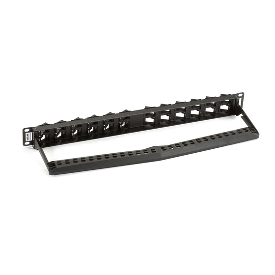
45° Side-Exiting Multmedia Panel
Direction of
IDC slot
Figure 5. IDC slot position.
6. Secure the back cables with the supplied cable ties.
NOTE: Do not overtighten the cables.
7. Figure 6 shows a completed installation.
Figure 6. Completed patch panel installation.
0118 965 6000 | www.blackbox.co.uk
JPMT1024-ANG
Black Box Tech
Support: FREE! Live.
24/7. Tech support
the way it should be.
Great tech support is just 30 seconds
away at 724-746-5500 or blackbox.com.
Customer
Order :
Call 0118 965 6150
Support
Information
FREE technical support
24 hours a day, 7 days a week:
Call 0118 965 6000
Mailing address:
Black Box Network Services
464 Basingstoke Road
Reading, Berkshire, RG2 0BG
Web site: www.blackbox.co.uk
E-mail: info@blackbox.co.uk
© Copyright 2011. Black Box Corporation. All rights reserved.
Black Box and the Double Diamond logo are registered trademarks of
BB Technologies, Inc. Any other trademarks mentioned in this manual
are acknowledged to be the property of the trademark owners.
Page 5
0118 965 6000 | www.blackbox.co.uk
45° Side-Exiting Multimedia Panel
Angles ports
BLACK BOX
®
to the sides.
Helps to reduce stress on the ports.
Horizontal cable management is not required.
1. Speci cations
Size: Without rear base installed: 1.75"H (1U) x
19"W x 0.625"D (4.5 x 48.3 x 1.6 cm);
With rear base installed: 1.75"H (1U) x 19"W x
5"D (4.5 x 48.3 x 12.7 cm)
Weight: 1.5 lb. (0.7 kg)
2. Overview
2.1 Introduction
The 24-Port 45° Side-Exiting Multimedia Panel
angles ports to the sides, which helps reduce
stress on the ports and eliminates the need for
horizontal cable management. The rear of the
panel has an optional cable support bar that
provides support to horizontal cables accessing
the panel.
Page 6
0118 965 6000 | www.blackbox.co.uk
JPMT1024-ANG
BLACK B
Advertisement

Summary of Contents for Black Box JPMT1024-ANG
- Page 1 © Copyright 2011. Black Box Corporation. All rights reserved. provides support to horizontal cables accessing Black Box and the Double Diamond logo are registered trademarks of the panel. BB Technologies, Inc. Any other trademarks mentioned in this manual are acknowledged to be the property of the trademark owners.
- Page 2 Make sure the locking knob is locked rst before Your package should include the following items. sliding in the keystone jack or support tting. See If anything is missing or damaged, contact Black Box mark “R” Figure 4. Slide in Technical Support on 0118 965 6000 or info@blackbox.co.uk.