Emerson Micro Motion 2400S Installation Manual
Hide thumbs
Also See for Micro Motion 2400S:
- Installation manual (44 pages) ,
- Product data sheet (28 pages) ,
- Configuration and use manual (188 pages)

Related Manuals for Emerson Micro Motion 2400S


Summary of Contents for Emerson Micro Motion 2400S
- Page 1 Installation Manual 20003402, Rev. DA January 2021 Micro Motion Model 2400S Transmitters Installation Manual...
- Page 2 European directives, and the complete ATEX Installation Drawings and Instructions are available on the internet at www.emerson.com/flowmeasurement or through your local Micro Motion support center. Information affixed to equipment that complies with the Pressure Equipment Directive can be found on the internet at www.emerson.com/flowmeasurement...
-
Page 3: Table Of Contents
Contents Chapter 1 Before you begin ......................5 Safety ............................ 5 Flowmeter components......................Transmitter installation overview ................... Flowmeter documentation ....................Chapter 2 Transmitter orientation and power supply ..............9 Moisture protection ....................... 9 Rotating the transmitter on the sensor (optional) ..............9 Rotating the user interface module on the transmitter (optional) ......... - Page 4 Model 2400S Transmitters...
-
Page 5: Before You Begin
Before you begin Before you begin This manual describes the procedures required to install the following transmitters: • Model 2400S transmitter with analog outputs • Model 2400S transmitter with PROFIBUS-DP • Model 2400S transmitter with DeviceNet Safety Read each safety message in this document carefully before proceeding to the next step. WARNING! Improper installation in a hazardous area can cause an explosion. -
Page 6: Transmitter Installation Overview
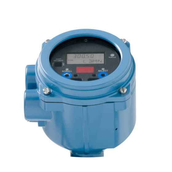
Before you begin Figure 1-1 Model 2400S transmitter Transmitter housing cover Conduit openings Clamping ring Sensor case Transmitter installation overview The Model 2400S transmitter component is mounted integrally with the sensor and grounded via the sensor. To install and ground the sensor, see the sensor documentation. Additional transmitter installation steps are documented in this manual: •... -
Page 7: Flowmeter Documentation
Sensor documentation shipped with the sensor Hazardous area installation See the approval documentation shipped with the transmitter, or download the appropriate documentation from the Micro Motion www.emerson.com/flowmeasurement web site at Transmitter configuration, Micro Motion Model 2400S Transmitters with Analog Outputs: ... - Page 8 Before you begin Model 2400S Transmitters...
-
Page 9: Transmitter Orientation And Power Supply
Transmitter orientation and power supply Transmitter orientation and power supply This section describes: • Rotating the transmitter on the sensor (optional) • Rotating the user interface module on the transmitter (optional) • Power supply requirements and wiring Moisture protection When rotating or wiring the transmitter, guard against condensation or excessive moisture inside the transmitter housing. -
Page 10: Rotating The User Interface Module On The Transmitter (Optional)
Transmitter orientation and power supply Figure 2-1 Rotating the transmitter on the sensor Clamping ring Feedthrough Feedthrough notches CAUTION! Do not rotate the housing more than 360°. Excessive rotation can damage the wiring and cause measurement error or flowmeter failure. Rotating the user interface module on the transmitter (optional) For easier access, you can rotate the user interface module (whether or not the transmitter... - Page 11 Transmitter orientation and power supply 2. Remove the transmitter housing cover and user interface module using the following steps (see Figure 2-2). a. Loosen the four transmitter housing cover screws. b. Remove the transmitter housing cover. c. Loosen the 2 user interface screws. d.
-
Page 12: Power Supply Requirements
Transmitter orientation and power supply Power supply requirements Model 2400S Analog and Model 2400S PROFIBUS-DP transmitters can accept either AC or DC power. The transmitter automatically recognizes the source voltage. Power supply requirements are: • AC power: 85–265 VAC 50/60 Hz 4 watts typical, 7 watts maximum •... -
Page 13: Wire The Power Supply
Transmitter orientation and power supply Example The transmitter is mounted 350 feet from a DC power supply. If you want to use 16 AWG cable, calculate the required voltage at the DC power supply as follows × × MinimumSupplyVoltage CableResistance CableLength 0.5A ×... - Page 14 Transmitter orientation and power supply Figure 2-3 Wiring the transmitter power supply Model 2400S Analog transmitter Warning flap screw User interface connector Warning flap Transmitter internal grounding screw + (L) – (N) Model 2400S PROFIBUS-DP transmitter Warning flap screw User interface connector Warning flap Transmitter internal grounding screw...
-
Page 15: Analog Transmitter I/O Wiring
Analog transmitter I/O wiring Analog transmitter I/O wiring This section describes how to wire I/O for Model 2400S Analog transmitters. Note: To wire I/O for Model 2400S PROFIBUS-DP and DeviceNet transmitters, see Section Important: Follow all corporate, local, and national safety requirements and electrical codes. Moisture protection When rotating or wiring the transmitter, guard against condensation or excessive moisture inside the transmitter housing. -
Page 16: Wire The Outputs
Analog transmitter I/O wiring Wire the outputs WARNING! Improper installation in a hazardous area can cause an explosion. For information about hazardous applications, refer to the appropriate Micro Motion approval documentation, shipped with the meter or available from the Micro Motion web site. CAUTION! Shut off power before installing the transmitter. - Page 17 Analog transmitter I/O wiring Figure 3-1 Basic mA output wiring with internal power – 820 Ohm maximum loop resistance Figure 3-2 HART/analog single-loop wiring with internal power – HART-compatible host or controller For analog communications: 820 Ohm maximum loop resistance For HART communications: •...
- Page 18 Analog transmitter I/O wiring Figure 3-3 Basic mA output wiring with external power – – load Note: Figure 3-5 for voltage and resistance values. CAUTION! Do not exceed 30 VDC input. Terminal current must be less than 500 mA. Excessive current will damage the transmitter.
- Page 19 Analog transmitter I/O wiring Figure 3-4 HART/analog single-loop wiring for external power – – HART- compatible host or controller load (250–600 Ohm resistance) Note: Figure 3-5 for voltage and resistance values. Figure 3-5 Required external voltage versus mA load resistance If communicating with HART, a minimum of 250 Ohms is required.
- Page 20 Analog transmitter I/O wiring Figure 3-6 HART multidrop wiring for internal or external power 24 VDC loop power HART-compatible HART-compatible supply required for HART SMART FAMILY ™ host or controller transmitter 4–20 mA passive Model 2400S transmitter Model 2400S transmitters Internal power External power 600 Ohm maximum resistance...
- Page 21 Analog transmitter I/O wiring Figure 3-7 Frequency output wiring for internal power – 000042 Counter Output voltage level is +24 VDC ±3% with high resistance load. Note: Figure 3-11 for output voltage versus load resistance. Figure 3-8 Frequency output wiring for external power –...
- Page 22 Analog transmitter I/O wiring CAUTION! Do not exceed 30 VDC input. Terminal current must be less than 500 mA. Excessive current will damage the transmitter. 3.3.3 Discrete output wiring Discrete output wiring depends on whether you will use internal or external power. The following diagrams are examples of proper wiring for these configurations: •...
- Page 23 Analog transmitter I/O wiring Figure 3-10 Discrete output wiring for external power – – 3–30 VDC Pull-up resistor or DC Relay Maximum sink current: 500 mA Note: Figure 3-12 for recommended resistor versus supply voltage. CAUTION! Do not exceed 30 VDC input. Terminal current must be less than 500 mA. Excessive current will damage the transmitter.
- Page 24 Analog transmitter I/O wiring Figure 3-11 Output voltage vs load resistance for internal power Open circuit output voltage = 24 VDC ±3% OPERATING REGION 20000 40000 60000 80000 100000 Load resistance (Ohms) Model 2400S Transmitters...
- Page 25 Analog transmitter I/O wiring Figure 3-12 Recommended pull-up resistor versus supply voltage for external power 4400 4000 3600 3200 2800 2400 2000 Recommended resistor value range 1600 1200 Supply voltage (Volts) Note: When using a discrete output to drive a relay, choose external pull-up to limit current to less than 500 mA. 3.3.4 Discrete input wiring Discrete input wiring depends on whether you will use internal or external power.
- Page 26 Analog transmitter I/O wiring Figure 3-13 Discrete input wiring for internal power – Figure 3-14 Discrete input wiring for external power PLC or other device – – Direct DC input (see (see Table 3-2 Table 3-2 Model 2400S Transmitters...
-
Page 27: I/O Wiring For Model 2400S Profibus-Dp And Devicenet Transmitters
I/O wiring for Model 2400S PROFIBUS-DP and DeviceNet I/O wiring for Model 2400S PROFIBUS-DP and DeviceNet transmitters This section describes how to wire I/O for Model 2400S PROFIBUS-DP and DeviceNet transmitters. Note: To wire I/O for Model 2400S Analog transmitters, see Chapter Important: Follow all corporate, local, and national safety requirements and electrical codes. - Page 28 I/O wiring for Model 2400S PROFIBUS-DP and DeviceNet transmitters Note: Do not open the power compartment unless you are also wiring the power supply. Note: Ground the PROFIBUS cable shield at both ends. At the 2400S, ground the cable shield in an appropriate cable gland. If using an optional PROFIBUS-DP Eurofast M12 connector, ground the cable shield using the threads of the connector.
-
Page 29: I/O Wiring For Model 2400S Devicenet Transmitters
I/O wiring for Model 2400S PROFIBUS-DP and DeviceNet Note: The Model 2400S PROFIBUS-DP transmitter does not have terminals for termination wiring. An external terminator is not required. The transmitter has an internal terminator. There is a switch on the user interface for enabling internal termination. - Page 30 I/O wiring for Model 2400S PROFIBUS-DP and DeviceNet transmitters Figure 4-3 Model 2400S DeviceNet I/O wiring Attach a 5-pin female Eurofast connector here Model 2400S Transmitters...
-
Page 31: Appendix A Dimensions And Specifications
I/O wiring for Model 2400S PROFIBUS-DP and DeviceNet Appendix A Dimensions and specifications Dimensions Figure A-1 Figure A-2 show the dimensions of the Model 2400S transmitter. For sensor dimensions, see the sensor data sheet. Figure A-1 Transmitter housing dimensions for painted aluminum housing inches 4.545 Dimensions in... - Page 32 I/O wiring for Model 2400S PROFIBUS-DP and DeviceNet transmitters Figure A-2 Transmitter housing dimenstions for stainless steel housing inches Dimensions in (mm) 5.70 (114,8) 5.20 (132,1) 5.70 (114,8) 5.20 (132,1) 0.793 (20,1) 1.586 (40,3) 4.515 (114,7) Note: Torque the cover screws to a minimum of 19 in-lbs (2,1 N-m). Model 2400S Transmitters...
-
Page 33: Physical Specifications
I/O wiring for Model 2400S PROFIBUS-DP and DeviceNet Physical specifications Housing Polyurethane-painted aluminum Optional: 316L stainless steel Weight Transmitter is mounted integrally with sensor. For weight of flowmeter, see product data sheet for sensor. Mounting and cabling Model 2400S transmitters are mounted integrally with sensor. The transmitter can be rotated on the sensor up to 360°... -
Page 34: Electrical Connections
I/O wiring for Model 2400S PROFIBUS-DP and DeviceNet transmitters Electrical connections Model 2400S Analog Input and output connections Two pairs of wiring terminals for transmitter inputs/ outputs. Screw terminals accept solid or stranded conductors, 26 to 14 AWG (0,14 to 2,5 mm Power connections One pair of wiring terminals accepts AC or DC power. -
Page 35: User Interface
I/O wiring for Model 2400S PROFIBUS-DP and DeviceNet User interface Model 2400S Analog With display Without display Model 2400S PROFIBUS-DP With display Without display Model 2400S DeviceNet With display Without display Installation Manual... - Page 36 I/O wiring for Model 2400S PROFIBUS-DP and DeviceNet transmitters Interface functions All models with or without display Suitable for hazardous area installation. User interface module can rotate 360° on the transmitter in 90° increments. Three-color status LED on user interface module ...
-
Page 37: Input/Output Signals
I/O wiring for Model 2400S PROFIBUS-DP and DeviceNet Input/output signals A.6.1 Model 2400S Analog Channel A One active or passive 4–20 mA output Not intrinsically safe Isolated to ±50 VDC from all other outputs and earth ground Maximum load limit: 820 ohms ... -
Page 38: Digital Communications
I/O wiring for Model 2400S PROFIBUS-DP and DeviceNet transmitters Digital communications All versions Service port One service port for temporary connections (requires removing transmitter housing cover) Uses RS-485 Modbus signal, 38.4 kBaud, one stop bit, no parity Address: 111 (not configurable) Wireless If transmitter has display, service port can be accessed with IrDA device (for example, a PDA running Pocket ProLink) without removing transmitter housing cover. -
Page 39: Environmental Limits
I/O wiring for Model 2400S PROFIBUS-DP and DeviceNet Environmental limits Ambient temperature limits Operating and storage: –40 to +140 °F (–40 to +60 °C) Below –4 °F (–20 °C), LCD responsiveness decreases and LCD may become difficult to read. Above 131 °F (55 °C), some darkening of the LCD panel might occur. Humidity limits 5 to 95% relative humidity, non-condensing at 140 °F (60 °C) Vibration limits... - Page 40 I/O wiring for Model 2400S PROFIBUS-DP and DeviceNet transmitters Model 2400S Transmitters...
-
Page 41: Appendix B Return Policy
I/O wiring for Model 2400S PROFIBUS-DP and DeviceNet Appendix B Return Policy Follow Micro Motion procedures when returning equipment. These procedures ensure legal compliance with government transportation agencies and help provide a safe working environment for Micro Motion employees. Failure to follow Micro Motion procedures will result in your equipment being refused delivery. - Page 42 F +44 0800 966 181 ©2021 Micro Motion, Inc. All rights reserved. The Emerson logo is a trademark and service mark of Emerson Electric Co. Micro Motion, ELITE, ProLink, MVD and MVD Direct Connect marks are marks of one of the Emerson Process Management family of companies.