Table of Contents
Advertisement
FOREWORD
FOREWORD
A message to hyundai lift truck operators ----------------------------------------------------------------------- 0-1
Introduction ------------------------------------------------------------------------------------------------------------------------ 0-2
How to use this manual ---------------------------------------------------------------------------------------------------- 0-3
EC regulation approved ----------------------------------------------------------------------------------------------------- 0-5
Safety labels ---------------------------------------------------------------------------------------------------------------------- 0-6
Guide (Direction, Serial number, Symbols) -------------------------------------------------------------------- 0-16
1. SAFETY HINTS
1. SAFETY HINTS
1. Daily inspection ------------------------------------------------------------------------------------------------------------- 1-1
2. Do's and don'ts -------------------------------------------------------------------------------------------------------------- 1-2
3. Seat belts ----------------------------------------------------------------------------------------------------------------------- 1-4
4. No riders ------------------------------------------------------------------------------------------------------------------------- 1-5
5. Pedestrians -------------------------------------------------------------------------------------------------------------------- 1-6
6. Operator protection -------------------------------------------------------------------------------------------------------- 1-7
7. Fork safety ------------------------------------------------------------------------------------------------------------------- 1-8
8. Pinch points ---------------------------------------------------------------------------------------------------------------- 1-9
9. Travel ------------------------------------------------------------------------------------------------------------------------------- 1-10
10. Grades, ramps, slopes and inclines ----------------------------------------------------------------------------- 1-11
11. Tip over --------------------------------------------------------------------------------------------------------------------------- 1-12
12. Surface and capacity ----------------------------------------------------------------------------------------------------- 1-14
13. Parking ---------------------------------------------------------------------------------------------------------------------------- 1-15
14. Refueling ------------------------------------------------------------------------------------------------------------------------ 1-16
15. Step --------------------------------------------------------------------------------------------------------------------------------- 1-17
16. Operator's safety rules -------------------------------------------------------------------------------------------------- 1-18
1. Loose loads -------------------------------------------------------------------------------------------------------------------- 2-1
2. Long and wide loads ----------------------------------------------------------------------------------------------------- 2-2
3. Rear swing --------------------------------------------------------------------------------------------------------------------- 2-2
4. Low overhead clearance ----------------------------------------------------------------------------------------------- 2-3
5. Fast turns and high loads ---------------------------------------------------------------------------------------------- 2-3
6. Right angle stacking ------------------------------------------------------------------------------------------------------ 2-4
7. Chain slack --------------------------------------------------------------------------------------------------------------------- 2-4
8. Pallets and skids ------------------------------------------------------------------------------------------------------------ 2-5
9. Caution for electrical lines --------------------------------------------------------------------------------------------- 2-5
10. Lifting loads -------------------------------------------------------------------------------------------------------------------- 2-6
CONTENTS
CONTENTS
Advertisement
Table of Contents

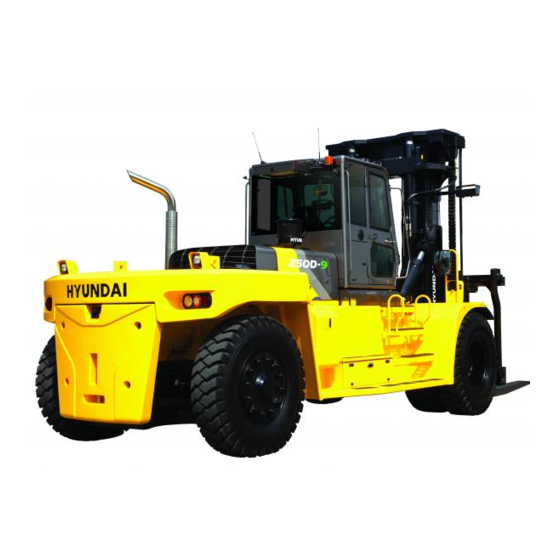
Summary of Contents for Hyundai 250D-9
-
Page 1: Table Of Contents
CONTENTS CONTENTS FOREWORD FOREWORD A message to hyundai lift truck operators ----------------------------------------------------------------------- 0-1 Introduction ------------------------------------------------------------------------------------------------------------------------ 0-2 How to use this manual ---------------------------------------------------------------------------------------------------- 0-3 EC regulation approved ----------------------------------------------------------------------------------------------------- 0-5 Safety labels ---------------------------------------------------------------------------------------------------------------------- 0-6 Guide (Direction, Serial number, Symbols) -------------------------------------------------------------------- 0-16 1. SAFETY HINTS 1. - Page 2 11. Side shift ------------------------------------------------------------------------------------------------------------------------- 2-6 12. Fork positioner --------------------------------------------------------------------------------------------------------------- 2-8 13. When solid tire are equipped ---------------------------------------------------------------------------------------- 2-8 3. KNOW YOUR TRUCK 3. KNOW YOUR TRUCK 1. General locations ----------------------------------------------------------------------------------------------------------- 3-1 2. Data/safety plate and decal ------------------------------------------------------------------------------------------ 3-2 3. Cab devices ------------------------------------------------------------------------------------------------------------------- 3-4 4.
- Page 3 6. EMERGENCY STARTING AND TOWING 6. EMERGENCY STARTING AND TOWING 1. How to tow a disabled truck -------------------------------------------------------------------------------------------- 6-1 2. How to use battery jumper cables ---------------------------------------------------------------------------------- 6-3 7. PLANNED MAINTENANCE AND LUBRICATION 7. PLANNED MAINTENANCE AND LUBRICATION 1. Introduction -------------------------------------------------------------------------------------------------------------------- 7-1 2.
-
Page 4: A Message To Hyundai Lift Truck Operators
HYUNDAI lift trucks are built to take hard work, but not abuse. They are built to be dependable, but they are only safe and efficient as the operator and the persons responsible for maintaining them. Do not make any repairs to this truck unless you have been trained in safe lift truck repair procedures and are authorized by your employer. -
Page 5: Introduction
HYUNDAI lift truck in a safe and correct manner. Your HYUNDAI lift truck has been designed and built to be as safe and efficient as today's technology can make it. As manufactured, for some models, it meets all the applicable mandatory requirements of ANSI B56.1-1988 Safety Standard for Powered Industrial Trucks. -
Page 6: How To Use This Manual
The descriptions and specifications included in this manual were in effect at the time of printing. HYUNDAI reserves the right to make improvements and changes in specifications or design, without notice and without incurring obligation. Please check with your authorized HYUNDAI dealer for information on possible updates or revisions. - Page 7 Acquaint yourself with the various procedures in this manual. Understand how all gauges, indicator lights, and controls function. Please contact your authorized HYUNDAI dealer for the answers to any questions you may have about your lift truck's features, operation, or manuals.
-
Page 8: Ec Regulation Approved
EC REGULATION APPROVED EC REGULATION APPROVED · Noise level (2000/14/EC and EN 12053) are as followings. Model (EU only) 250D-9 108 dB 76 dB · The value of vibrations transmitted by the operator's seat are lower than standard value of (2005/88/EC) -
Page 9: Safety Labels
30 31 CABIN INSIDE - RH CABIN INSIDE - LH VIEW A CONSOLE BOX 18 12 24 19 10 25 250D9OM101-1 Logo (HYUNDAI) 13 Start warning 28 Starting procedure Warning-mast 16 Fork positioner-LH 29 Load capacity Hand caution 17 Fork positioner-RH... - Page 10 2. DESCRIPTION 2. DESCRIPTION There are several specific warning labels on this machine please become familiarized with all warning labels. Replace any safety label that is damaged, or missing. 1) 1) WARNING-MAST WARNING-MAST (ltem 2) This warning label is positioned on the both side of the mast.
- Page 11 4) 4) HAND CAUTION HAND CAUTION (Item 3) This warning label is positioned on the bottom side of mast. It warns of the danger of injury from It warns of the danger of injury from m o v e m e n t b e t w e e n r a i l s , c h a i n s , m o v e m e n t b e t w e e n r a i l s , c h a i n s , sheaves, fork carriage, and other parts of sheaves, fork carriage, and other parts of...
- Page 12 8) 8) SAFETY INSTRUCTION SAFETY INSTRUCTION (Item 30) Truck for USA or equipped with *OPSS. This warning label is positioned on the left SAFETY INSTRUCTIONS window of cabin inside if the truck is for USA or equipped with *OPSS. OPSS. This forklift equipped with an operator existence sensingsing system per ISO 3691 Power travel movement of the truck shall be possible only if the...
- Page 13 If necessary or the engine would not start, 30 seconds lift pump cycle can be repeated until air is purged from low pressure side of fuel system. Re-cranking. If the engine still would not start, please contact the nearest HYUNDAI or Cummins dealers. 0-10...
- Page 14 START WARNING START WARNING (Item 13) This warning label is positioned on the middle side of dashboard cover. 5 6’ ※ Start key switch after 5~6 seconds from Start key switch after 5~6 seconds from 92AD-00920 O N p o s i t i o n . I t n e e d s a p p r o x 5 ~ 6 O N p o s i t i o n .
- Page 15 AIR COMPRESSOR-CABIN AIR COMPRESSOR-CABIN (Item 31) This warning label is positioned on the left window of cabin inside. 1. Park on a flat place to use the air compressor. 2. Be sure the engine working during the use of air compressor, Park on a flat place to use the air After the use, make sure the compressor switch off.
- Page 16 A special air bleed valve is accumulator. A special air bleed valve is necessary for this operation, so please necessary for this operation, so please contact your Hyundai distributor. contact your Hyundai distributor. 0-13...
- Page 17 DEF / ADBLUE® DEF / ADBLUE® (Item 38) This label is positioned on the DEF / AdBlue® tank of the right side frame. ※ Fill the DEF / AdBlue® only. Fill the DEF / AdBlue® only. ※ Never use diesel oil. Never use diesel oil.
- Page 18 HAMMER HAMMER (Item 27) This label is located on the rear right side of the cabin inside. ※ The rear window serves as an alternate The rear window serves as an alternate exit. exit. ※ To remove rear window, pull the ring and To remove rear window, pull the ring and push out the glass.
-
Page 19: Guide (Direction, Serial Number, Symbols)
GUIDE GUIDE 1. DIRECTION 1. DIRECTION The directions of this truck indicate forward, Front backward, right and left when truck is in the travelling direction. Left Right Rear 250D9OM01 2. SERIAL NUMBER 2. SERIAL NUMBER Inform following when you order parts or the truck is out of order. TRUCK SERIAL NUMBER It's shown on front of the right side frame. -
Page 20: Daily Inspection
1. GENERAL SAFETY RULES 1. GENERAL SAFETY RULES 1. DAILY INSPECTION 1. DAILY INSPECTION At the beginning of each shift, inspect your truck and fill out a check, maintenance and lubrication table. Check for damage and maintenance problems. Have repairs made before you operate the truck. Do not make repairs yourself. -
Page 21: Do's And Don'ts
2. DO'S AND DON'TS 2. DO'S AND DON'TS Do watch for pedestrians. D35AOM03 Do wear safety equipment when required. D35AOM05 Don't mix drugs or alcohol with your job. D35AOM02 Don't block safety or emergency equipment. 40B9OM04 Don't smoke in NO SMOKING areas or when charging. D35AOM06... - Page 22 Don't operate the truck outdoors in rainy day. ※ Exclude the truck equipped cabin. Exclude the truck equipped cabin. 250D9OM07 Exhaust gas is dangerous. Do not operate the truck at the inhouse, if possible. Provide adequate ventilation when working in a closed space. 250D9OM08...
-
Page 23: Seat Belts
3. SEAT BELTS 3. SEAT BELTS Always buckle up for the truck equipped Always buckle up for the truck equipped with safety belt. with safety belt. 160D7OM09 Seat belts can reduce injuries. Seat belts can reduce injuries. 160D7OM11... -
Page 24: No Riders
4. NO RIDERS 4. NO RIDERS The operator is the only one who should be on a truck. 250D9OM12 Never transport personnel on the forks of a lift truck. 250D9OM14... -
Page 25: Pedestrians
5. PEDESTRIANS 5. PEDESTRIANS Watch where you are going. Look in the direction of travel. Pedestrians may use the same roadway you do. Sound your horn at all intersections or blind spots. 250D9OM05 Watch for people in your work area even if your truck has warning lights or alarms. -
Page 26: Operator Protection
6. OPERATOR PROTECTION 6. OPERATOR PROTECTION Stay inside the cabin. Always keep your body within the confines of the truck. Do not operate truck without cabin or Do not operate truck without cabin or overhead guard, unless condition prevent overhead guard, unless condition prevent use of it. -
Page 27: Fork Safety
7. FORK SAFETY 7. FORK SAFETY Never allow anyone to walk under raised forks. D255OM17A There is special equipment to raise people for overhead work. DO NOT USE LIFT TRUCKS. 250D9OM14 Always lower the load slowly. Raise and lower with mast vertical or tilted slightly back (Never forward). -
Page 28: Pinch Points
8. PINCH POINTS 8. PINCH POINTS Keep hands, feet and legs out of the Keep hands, feet and legs out of the mast. mast. D255OM61 Don't use the mast as a ladder. Don't use the mast as a ladder. 250D9OM62 Never try to repair the mast, carriage, Never try to repair the mast, carriage, chain, or attachment by yourself. -
Page 29: Travel
9. TRAVEL 9. TRAVEL Travel with the load near the floor/ground, with mast tilted back to cradle the load whenever possible. Never lift or lower the load when the Never lift or lower the load when the truck is in motion. truck is in motion. -
Page 30: Grades, Ramps, Slopes And Inclines
10. GRADES, RAMPS, SLOPES AND INCLINES 10. GRADES, RAMPS, SLOPES AND INCLINES Never turn on a grade, either loaded or unloaded. Never turn on a grade, either loaded or unloaded. Unloaded-Forks downgrade 250D9OM30 Loaded - Forks upgrade 250D9OM33 1-11... -
Page 31: Tip Over
11. TIP OVER 11. TIP OVER 1) 1) LATERAL TIP OVER LATERAL TIP OVER L a t e r a l t i p o v e r c a n o c c u r w i t h a combination of speed and sharpness of turn. - Page 32 3) 3) WHAT TO DO IN CASE OF A TIP OVER WHAT TO DO IN CASE OF A TIP OVER If your truck starts to tip over, Do not If your truck starts to tip over, Do not jump. jump. Brace yourself as illustrated right.
-
Page 33: Surface And Capacity
12. SURFACE AND CAPACITY 12. SURFACE AND CAPACITY Avoid these conditions. They can cause a truck to tip over or lose traction for braking or driving. Know the weight of your truck and load. Know the weight of your truck and load. Especially when using elevators, Know Especially when using elevators, Know the capacity of the elevator you intend to... -
Page 34: Parking
13. PARKING 13. PARKING Never park on a grade. 250D9OM41 Always come to a complete stop before leaving truck. Be sure travel control is in NEUTRAL. 250D9OM42 Lower forks fully to floor and tilt forward. 250D9OM44 Set parking brake. Position 1 : OFF (Release) Position 2 : ON (Lock) Turn key to OFF position. -
Page 35: Refueling
14. REFUELING 14. REFUELING Before adding oil, check around truck for oil leakage. 250D9OM47 Keep away from fire when adding oil or during operation. 250D9OM48 After adding oil, wipe off any oil spilled on truck. 250D9OM49 1-16... -
Page 36: Step
15. STEP 15. STEP When getting on or off the truck, use the step provided. 250D9OM50 Do not jump up or down from the truck. 250D9OM52 1-17... -
Page 37: Operator's Safety Rules
16. OPERATOR'S SAFETY RULES 16. OPERATOR'S SAFETY RULES All operational functions require that the operator be seated in the operator's seat. Always buckle up if a seat belt is Always buckle up if a seat belt is provided. provided. 250D9OM18 Parking brake must be locked in the PARK POSITION before exiting from the vehicle. -
Page 38: Operating Hazards
2. OPERATING HAZARDS 2. OPERATING HAZARDS 1. LOOSE LOADS 1. LOOSE LOADS Loose or unbalanced loads are dangerous. Loose or unbalanced loads are dangerous. Observe these precautions. Observe these precautions. Never carry loose or uneven material. 250D9OM53 Center wide loads. 250D9OM55 Stack and band loose material. -
Page 39: Long And Wide Loads
2. LONG AND WIDE LOADS 2. LONG AND WIDE LOADS With long or wide loads, you need more With long or wide loads, you need more room. So slow down and watch your room. So slow down and watch your clearance. -
Page 40: Low Overhead Clearance
4. LOW OVERHEAD CLEARANCE 4. LOW OVERHEAD CLEARANCE Know the height of your truck, with and Know the height of your truck, with and without a load. Check your clearances. without a load. Check your clearances. Keep the load low and tilted back. Keep the load low and tilted back. -
Page 41: Right Angle Stacking
6. RIGHT ANGLE STACKING 6. RIGHT ANGLE STACKING When right angle stacking or moving with When right angle stacking or moving with a raised load to clear low objects, avoid a raised load to clear low objects, avoid sharp turns and move slowly. sharp turns and move slowly. -
Page 42: Pallets And Skids
8. PALLETS AND SKIDS 8. PALLETS AND SKIDS Do not move or store materials on Do not move or store materials on damaged pallets or skids. Items can fall damaged pallets or skids. Items can fall through them causing severe injury or through them causing severe injury or death. -
Page 43: Lifting Loads
10. LIFTING LOADS 10. LIFTING LOADS Never permit any persons to stand or Never permit any persons to stand or pass under lifted load. pass under lifted load. 250D9OM58 Never use wire rope to lift a load. Never use wire rope to lift a load. 250D9OM60... -
Page 44: Fork Positioner
3. KNOW YOUR TRUCK 3. KNOW YOUR TRUCK 1. GENERAL LOCATIONS 1. GENERAL LOCATIONS 250D9OM54 Mast Tilt cylinder 13 Bonnet Lift chain Cabin 14 Counterweight Lift cylinder Head light-fender 15 Rear wheel Fork positioner cylinder 10 Work lamp-mast 16 Front wheel Carriage 11 Work lamp-cabin rear 17 Rear combination lamp... -
Page 45: Data/Safety Plate And Decal
Truck serial number An identification number assigned to this particular truck and should be used when requesting information or ordering service parts for this truck from your authorized HYUNDAI dealer. The serial number is also stamped on the frame. Attachment description (If any installed) The user must see that the truck is marked to identify the attachment (s), including the weight of the truck/attachment combination and truck capacity with the attachment. - Page 46 OPERATOR SAFETY WARNING DECAL 110D9OM59 Safety and warning decals are placed in conspicuous locations on the truck to remind you of essential procedures or to prevent you from making an error that could damage the truck or possibly cause personal injury. You should know, understand, and follow these instructions.
-
Page 47: Cab Devices
3. CAB DEVICES The ergonomically designed console box and suspension type seat provide the operator with comfort. ELECTRONIC MONITOR SYSTEM The centralized electronic monitor system allows the status and conditions of the truck to be monitored at a glance. It is equipped with a safety warning system for early detection of truck malfunction. Front Rear Cluster... -
Page 48: Cluster
4. CLUSTER STRUCTURE The cluster consists of gauges, lamps, buttons and LCD as shown below, to warn the operator in case of abnormal truck operation or conditions for the appropriate operation and inspection. Gauges : Indicate operating status of the truck. Warning lamps : Indicate abnormality of the truck. - Page 49 GAUGE Speed meter The speed meter displays the speed of truck in mph and km/h. - 0~50 km/h - 0~31 mph 50D93CD03K Fuel gauge This gauge indicates the amount of fuel in the fuel tank. Fill the fuel when the indicator moves E point, refuel as soon as possible to avoid running out of fuel.
- Page 50 WARNING LAMPS DEF low level warning lamp Transmission oil temp warning lamp Engine coolant temp warning lamp Engine check warning lamp Fuel low level warning lamp Battery charge warning lamp Seat belt warning lamp Fan error warning lamp Air cleaner warning lamp Transmission error warning lamp Brake system temp warning lamp Brake system pressure warning lamp...
- Page 51 Engine oil pressure warning lamp This lamp comes ON for a while after starting the engine because of the low oil pressure. If the lamp comes ON during engine operation, shut OFF engine immediately. Check oil level. 50D93CD18 Air cleaner warning lamp This lamp operates by the vacuum caused inside when the filter of air cleaner is clogged.
- Page 52 Immediately pull the truck to a convenient stop. Stop the engine. Investigate the cause. Consult a HYUNDAI dealer to investigate the cause. Do not operate until the cause has been corrected. 50D93CD19...
- Page 53 50% derate, 30 min. Engine error code 3712 DEF level final derate warning Flash Contact Hyundai service center or dealer. Manual SCR cleaning method Manual SCR cleaning applies if the machine is in a fireproof area and there is no plan to turn off the machine during the SCR cleaning.
- Page 54 Engine stop warning lamp When this warning lamp lights ON, stop the engine immediately and and check the DEF level and related parts of the engine. Please contact your Hyundai service center or local dealer. 50D9CD33 (16) Fan error warning lamp This lamp is turned ON when the cooling fan error occurs.
- Page 55 PILOT LAMPS DEF level pilot lamp Left turning pilot lamp Right turning pilot lamp Parking brake pilot lamp Head light pilot lamp Expendables replacement indicator lamp Inching pilot lamp Fuel warmer pilot lamp Preheater pilot lamp HEST pilot lamp SCR cleaning inhibit pilot lamp OPSS pilot lamp Cooling fan reverse pilot lamp 250D9CD02-2...
- Page 56 Head light pilot lamp This lamp comes ON when the main light switch is operated to 2nd step. 50D9CD07 Preheater pilot lamp This lamp lights ON when start switch is turned clockwise to the ON position. Light will turn off after approximately 15~45 seconds, depending on engine coolant temperature, indicating that preheating is completed.
- Page 57 SCR cleaning inhibit pilot lamp This pilot lamp lights ON when the SCR cleaning switch is pushed inhibit position, therefore automatic and manual SCR cleaning can not occur. It should inhibited, before caused fire due to the exhaust gas in high temperature. Refer to the page 3-35 for the SCR cleaning switch.
- Page 58 CLUSTER BUTTON Each button has the following function. Menu button Camera/Enter button Move button Buzzer stop/ESC button 50D9CD121 Buzzer stop/ESC button This button is used to stop the buzzer sound. If another alarm condition occurs after this button has been pressed, the alarm buzzer will re-sound.
- Page 59 Main screen You can select or set the menu by the button of the cluster. Please refer to the page 3-15 for the selection and change of the menu and input value. Main screen Main menu screen Sub menu screen MENU 180D9CD10 50D9CD11...
- Page 60 Main menu Main menu Sub menu Description Model select Model select Tilt setting Tilt setting (mast and vehicle angle) Rear angle setting Rear angle setting Weight sensor setting Cross-section, load weight adjust, weight display setting, load indicator buzzer ESL setting ESL setting Vehicle max speed limit Vehicle max speed limit (10~30 km)
- Page 61 Equipment Choose the equipment 180D9CD20 50D9CD21 To enter the menu, you must input user password. Default password is ‘00000’ You should set password by fi ve to ten digit. Model select 180D9CD22 50D9CD23 50D9CD24 Select the Model The initial model is selected at the factory, so don’t change the different model.
- Page 62 Weight sensor setting Cross-section 180D9CD35-1 180D9CD36-1 180D9CD37 Enter the designated cross-section (cm Mast spec 250D-9 V-Mast 402.12 TS-Mast 508.94 180D9CD38 Load weight adjust Unloaded status adjustment In the unloaded from the ground waiting 5 seconds after lift 30 cm, and tare ON.
- Page 63 180D9CD35-1 50D9CD39-1 50D9CD49 Initialization It is initialized loaded status and unloaded status. 50D9CD51-1 50D9CD50-1 Weight display setting 180D9CD35-1 50D9CD53-1 50D9CD54 Select the number of points of weight value display. 50D9CD55 Overload warning buzzer 180D9CD35-1 50D9CD57-1 50D9CD58-1 Choose using buzzer when over weight. 3-19-1...
- Page 64 ESL setting 180D9CD59 50D9CD60 180D9CD61K 180D9CD55 50D9CD61-2 50D9CD61-3 180D9CD55 50D9CD62 50D9CD63 180D9CD55 50D9CD64-1 Set ON/OFF function for using limitation of ignition and time for starting. Set time 5 minutes for starting : In 5 minutes you can restart without password, but after 5 minutes, you should input password for starting. 3-20...
- Page 65 Vehicle max speed limit 180D9CD65-1 50D9CD66-1 50D9CD67 Set the maximum speed. 10 km/h~30 km/h (1 km/h intervals) 50D9CD68 180D9CD69 50D9CD70-1 AEB setting 180D9CD71-1 180D9CD72 Press OK button, then calibration will be started, for cancel, press Menu/ECS/Enter button. When it is fi nished (OK sign at gear box), Press Menu/ECS/Enter button. Start the engine : AEB start KEY ON : Brake pedal sensor calibration (R) MCU / Cluster information...
- Page 66 Cooling fan reverse mode 180D9CD101-1 180D9CD103-1 Manual : The fan only rotate in reverse direction while you hold down the manual button. Automatic : The fan rotate in reverse direction at pre-set interval. - Interval : 30 minutes ~ 5 hours - Time : 30 seconds ~ 5 minutes Refer to the page 3-35 for the cooling fan control switch.
- Page 67 Finger tip setting Lever position setting 50D9CD74 50D9CD74 50D9CD74 50D9CD74 50D9CD74 50D9CD74 50D9CD74 50D9CD74 50D9CD74 50D9CD74 50D9CD74 Ability to set up the maximum Pull, Push (Min,Max) value and neutral value (Mid) of lever. Finger Tip lever set up about 0.5V~2.5V~4.5V. You must be to move with actual Lever.
- Page 68 Lever deadzone setting 50D9CD74 50D9CD74 50D9CD74 50D9CD74 50D9CD74 50D9CD74 50D9CD74 50D9CD74 50D9CD74 50D9CD74 50D9CD74 Ability to prevent the Value output due to a tiny error of the neutral Lever state (2.5V) ex) If you set up the Upper : 0.26, Lower : 0.24, Lever operating range will be Upper zone : 2.76V (2.5+0.26) ~ 4.5V (Lever Max value) Lower zone : 2.26V (2.5-0.24) ~ 0.5V (Lever Min value)
- Page 69 Valve setting 50D9CD74 50D9CD74 50D9CD74 50D9CD74 50D9CD74 50D9CD74 50D9CD74 50D9CD74 50D9CD74 50D9CD74 50D9CD74 Current Setting : Current setting for input each Valve Coil, it is to set up each maximum value of movements according ot the current value (Unit % (Over 110D-9 only), mA (Under 80D-9 Only) ex) If the Max value increase, the maximum speed will also increase.
- Page 70 Maintenance Choose the maintenance 180D9CD75-1 180D9CD76 To enter the Menu, you must input user password. Default password is ‘00000’ You should set password by fi ve to ten digit. Failure history a. Current failure history 180D9CD77 180D9CD77-1 180D9CD78 Show the failure status of the current engine, transmission and/or air conditioner.
- Page 71 c. Delete logged fault 180D9CD77 180D9CD77-3 180D9CD78-2 Initialize of the past logged fault history. 180D9CD79-1 Maintenance management 180D9CD81 180D9CD82 180D9CD83 Exchange expendable supplies. Change the replacement cycle. Show the Maintenance 180D9CD84 180D9CD85 Information below 10. (Delete the old item, when Information have more than 10) 180D9CD86 180D9CD87...
- Page 72 Signal status 180D9CD89-1 50D9CD90 180D9CD91 Display information of each sensors. 50D9CD92 180D9CD93 User password change 180D9CD94-1 50D9CD95-1 50D9CD96-1 You should set password by fi ve to ten digit. 180D9CD97 50D9CD97-1 Alternate torque 180D9CD201-1 50D9CD1000 50D9CD1002 Select the alternate torque mode 3-23...
- Page 73 Opening of communication 180D9CD98-1 180D9CD99 180D9CD100 When successfully opened RMCU communication, except for the RMCU comm. 180D9CD102-1 180D9CD101 180D9CD102 180D9CD104-1 180D9CD105-1 180D9CD107 180D9CD106 3-23-1...
- Page 74 Display setting Choose the display setting No password is required. 180D9CD108 LCD adjustment 180D9CD109 50D9CD110 180D9CD111 50D9CD112 180D9CD113 Manual : Manual setting for LCD brightness. Automatic : Automatic control of LCD brightness as set level of Day/Night. Setting day time : Set the time for daylight. (If you set the time for daylight, the rest time will be night.) 180D9CD114 180D9CD115...
- Page 75 Unit setting 180D9CD118 50D9CD118-1 50D9CD119 Change units of temperature / speed / wight / pressure. Language setting 180D9CD120 180D9CD121 180D9CD122 Set the language used by your device. (13 Multiple language) 50D9CD123 A/S phone number 50D9CD124 50D9CD125 180D9CD126 Check and change of contact information for customer service. ESL password change 50D9CD127 180D9CD128...
- Page 76 Maintenance management 50D9CD131 50D9CD132-1 50D9CD133-1 Show the maintenance information (replacement cycle, elapsed time, change count, alarm information). 3-26...
- Page 77 In case of possible errors in the system, a wrench appears on the display, combined with indication of the error number. Also sporadically occurring errors can be indicated. Transmission message display 180D93ACD33 If it happens error codes, consult with Hyundai service center to repair the fault. 3-27...
- Page 78 DISPLAY DURING AEB-MODE Symbol Meaning Remarks K1..K3 Calibrating clutch K1...K3, KV or KR KV, KR resp. _and Kx Wait for start, initialization of clutch Kx, x : 1, 2, 3, V, R and Kx Fast fill time determination of clutch Kx =and Kx Compensating pressure determination of clutch Kx...
- Page 79 INITIALIZING THE INCHING SENSOR Start engine after parking the machine on flat floor and blocking wheels. Release parking brake and keep neutral gear shift. Adjust the inching sensor linkage so that the regular voltage is supplied to inching sensor when operating the pedal.
-
Page 80: Switches
6. SWITCHES Main light switch Work lamp switch Hazard switch(opt) Beacon lamp switch(opt) Cover Parking brake switch Auto/manual changeover switch Inching switch Fuel warmer switch In/decrement switch SCR cleaning switch Power/standard switch Rear wiper/washer switch Top wiper/washer switch(opt) Air compressor switch (opt) Seat heater switch (opt) Cooling fan control switch (opt) Cover... - Page 81 START SWITCH There are three positions, OFF, ON and START. (OFF) : None of electrical circuits activate. (ON) : All the systems of truck operate. (START) : Use when starting the engine. Release key immediately after starting. 77073CD41 HAZARD SWITCH (OPTION) Use for parking, or loading truck.
- Page 82 WORK LAMP SWITCH This switch is used to operate the work lamps by two steps. First step : Front work lamp comes ON. Second step : Rear work lamp comes ON. 180D9OM16 AUTO/MANUAL CHANGEOVER SWITCH Manual mode ( ) Press the top of the switch for the manual mode of the autoshift function.
- Page 83 FUEL WARMER SWITCH This switch is used to heat the fuel of pre-heater. 35D9AOM19 BEACON SWITCH (OPTION) This switch turn ON the strobe light. 35D9AOM18 INC/DECREMENT SWITCH When engine running, the low rpm of engine increase or decrease by 25 rpm by operating this switch. Engine low rpm returns to normal value when engine restarted.
- Page 84 CAB LAMP SWITCH This switch turns ON the cab room lamp. 73033CD24 MULTI FUNCTION SWITCH Front wiper and washer switch When the switch is in J position, the wiper moves intermittently. When placed in position, the wiper moves continuously. If you push the grip of the lever, washer liquid will be sprayed and the wiper will be activated 2-3 times.
- Page 85 SCR (Selective Catalytic Reduction) CLEANING SWITCH This switch is used to select the cleaning function of the SCR. Inhibit position ( ) The inhibit position disallows any automatic or manual SCR cleaning. This may be used by operator to prevent SCR cleaning when the machine is operating in a hazardous environment is concerned 50D9OM21A about high temperature.
- Page 86 AIR COMPRESSOR SWITCH (option) This switch is used to activate the air compressor. 110D9CD61 SEAT HEAT SWITCH This switch is used to heat the seat. 110D9CD62 COOLING FAN CONTROL SWITCH (option) This switch use to control the cooling fan. AUTO This switch has three positions.
-
Page 87: Control Device
7. CONTROL DEVICE Lift lever Tilt lever Steering wheel 3-spool lever(opt) Gear selector lever 4-spool lever(opt) Inching pedal 5-spool lever(opt) Brake pedal Accelerator pedal 110D9CD08 LIFT LEVER LIFT PULL the lever BACK to LIFT the forks. Lower LOWER PUSH the lever FORWARD to LOWER the load. Lift HOLDING When the lever is released, the lifting or lowering action stops. - Page 88 LEVER FOR SIDE SHIFT LH MOVEMENT Push the lever forward to move the left hand for the side shift. RH MOVEMENT Pull the lever backward to move the right hand for the side shift. 50D9CD17 LEVER FOR SIDE SHIFT WITH FORK POSITIONER FORK POSITIONER (SYNCHRONIZER TYPE) OUTSTRECH THE FORKS Outstrech...
- Page 89 RH FORK MOVEMENT Outward - Push the lever forward to move outward for the RH fork. - Pull the lever backward to move inward for the RH fork. Inward 50D9CD22 GEAR SELECTOR LEVER This lever is used for gear selection, forward 3 stages and reverse 3 Acceleration stages.
- Page 90 ACCELERATOR PEDAL This pedal controls the engine speed. The engine speed will increase in proportion to the degree of force applied to this pedal. Unless this pedal is pressed, the truck will run at low idling. 160D7ECD32 INCHING PEDAL Inching pedal is used for fine control of forward and reverse movement when lifting up or putting down loads.
-
Page 91: Air Conditioner And Heater
8. AIR CONDITIONER AND HEATER Fuel auto air conditioner and heater are equipped for pleasant operation against outside temperature and defrost on window glass. Fan speed control knob Outlet control button Air conditioner button Air inlet control button Temperature control knob Air conditioner switch 110D9CD90 AIR CONDITIONER BUTTON... - Page 92 OUTLET CONTROL BUTTON There are five kinds of air flow. Face Rear Face and rear Face and defrost Defrost The pilot lamp is turned ON when the button is pushed. 50D9CD51 TEMPERATURE CONTROL KNOB This knob regulates the temperature of air. Right side (red zone) : Cool down air temperature Left side (blue zone) : Heat up air temperature 50D9CD53...
-
Page 93: Others
9. OTHERS Front Rear Radio and USB player Monitor(option) Cigar lighter 12V socket Fuse box Handsfree(option) Remote controller(option) Seat 110D9CD09 CIGAR LIGHTER This can be used when the engine starting switch is ON. The lighter can be used when it springs out in a short while after being pressed down. - Page 94 TRANSMISSION CONTROL UNIT (TCU) The control unit is shifting the required speeds fully-automatically under consideration of the following criteria. Gear selector lever position Driving speed Load level 77073CD91 RADIO AND USB PLAYER BASIC FUNCTIONS LCD display 75793CD62-2 FRONT PANEL PRESENTATION -------- Audio selection button ------- Preset memory button 5 D- ---------------- Directory down...
- Page 95 GENERAL Power and volume button Power ON/OFF button Press power button to turn the unit ON or OFF shortly. When the power is ON, the previous mode (last memory) will appear. Volume up / down control 75793CD66 Turn volume up / down button right to increase the volume level. The level will be shown in VOLUME xx on the LCD display.
- Page 96 HANDSFREE (OPTION) Allow you to dial a call or to have a conversation without holding your handset. Use the remote controller when making and answering a calls or ring off. Indicator lamp Private call jack socket Handsfree jack socket USB socket Mobile phone stroage box Service socket 21093CD51...
- Page 97 Handsfree jack socket Connect the jack cable when call by handsfree. Use the special adapter when jack cable is not interchangeable. Check the jack type of mobile phone before use. 21093CD51D Indicator lamp This lamp is turned ON when the handsfree mode selected. 21093CD51E 3-59...
- Page 98 (connection process of the mobile phone and handsfree), you can Call button hear beep sounds three times. 55I3CD26 The mobile phone finds bluetooth named " HYUNDAI". Select "HYUNDAI" and set "connect with Bluetooth on the mobile phone". HYUNDAI · Default password : 0000 PAIRING 55I3CD27 The Bluetooth pairing is made, the LCD screen shows "CONNECTED".
- Page 99 REMOTE CONTROLLER (OPTION) Radio handsfree jack External speaker LED (null) External speaker microphone (null) Handsfree jack MIC Power/volume switch External speaker switch (null) Handsfree mode button CALL button SEEK button SEEK button MODE button MUTE button TALK button Radio calling mode button 55I3CD31 Power and volume switch This switch is used to turn the audio or handsfree ON or OFF.
- Page 100 Handsfree MIC This MIC transfers user voice to receiver of the call when making a call by handsfree. 55I3CD31D Seek button If this button pressed, the radio automatically stops at the next frequency of broadcasting for your listening. This button enable to select the song of the MP3 from USB. : Turn a station of higher frequency and the next song of the MP3.
- Page 101 Radio calling mode button Press this button, activated or deactivated the radio handsfree function. As long as you do not press this button, you can hear the other party. 55I3CD31H The LED is turned ON when this button is activated. The LED turned OFF when the audio mode or the mobile phone handsfree calling mode is activated.
- Page 102 MONITOR (OPTION) · Adjusting the angle Upwards and downwards up to 7˚, swivels left and right up to 15˚. Sunshade LCD (7") Buttons 50D9CD211 Symbol Name Description LEFT - Move the Menu (left). Lower the value. - Enter the OSD menu MENU / ENTER - Choose the menu RIGHT...
- Page 103 Operation CAM set 50D9CD200 50D9CD201 Set the number of camera channels on screen. 1 CH (standard) Display one camera image on screen. Press left or right key to change the camera channel. Rear Front Side 1 Side 2 50D9CD202K 2 CH (dual) Display two camera images on screen.
- Page 104 Gear linkage mode 50D9CD205 50D9CD206 Depending on the gear state (forward/ backward), camera channel is switched automatically. Brightness setting 50D9CD207 50D9CD208 Adjust the display brightness. Language 50D9CD209 50D9CD210 Set the language (13 multiple language). 3-66...
-
Page 105: Operator Maintenance And Care
Do not make repairs yourself unless you are trained in lift truck repair procedures and authorized by your employer. Have a qualified mechanic make repairs using genuine HYUNDAI or HYUNDAI- approved parts. Do not operate a truck if it is in need of repair. If it is in an unsafe condition, remove the key Do not operate a truck if it is in need of repair. - Page 106 2) 2) FUNCTIONAL CHECKS FUNCTIONAL CHECKS Check the operation of the truck as follows. ※ Before performing these checks, familiarize yourself with the starting, operating, and Before performing these checks, familiarize yourself with the starting, operating, and shutdown procedures in Section 5 of this manual. Also, know the safety rules given in shutdown procedures in Section 5 of this manual.
-
Page 107: Suggestion For New Truck
2. SUGGESTION FOR NEW TRUCK 2. SUGGESTION FOR NEW TRUCK It takes about 100 operation hours to enhance its designed performance. Operate according to below three steps and avoid excessive operation for the initial 100 hours. Avoid excessive operation for initial 100 hours Service meter Load... -
Page 108: Fuel Safety Practices
3. FUEL SAFETY PRACTICES 3. FUEL SAFETY PRACTICES REFUELING DIESEL TRUCKS REFUELING DIESEL TRUCKS 100D7OM106 Stop the engine when refueling. Stop the engine when refueling. All lights and flames shall be kept at a All lights and flames shall be kept at a safe distance while refueling. -
Page 109: Starting And Operating Procedures
5. STARTING AND OPERATING PROCEDURES 5. STARTING AND OPERATING PROCEDURES 1. BEFORE OPERATING THE TRUCK 1. BEFORE OPERATING THE TRUCK Be sure that you have read and understand the information in this Operator's Manual and are trained and authorized before operating the lift truck. A lift truck can be dangerous if not used properly. -
Page 110: Check Before Operation
2. CHECK BEFORE OPERATION 2. CHECK BEFORE OPERATION The Occupational Safety and Health Act (OSHA) required that truck users examine their trucks before each shifts to be sure they are in safe working order. Defects when found shall be immediately reported and corrected. The truck shall be taken out of service until it has been restored to safe operating condition. -
Page 111: Check Before Starting Engine
CHECK FOR WATER OR OIL LEAKAGE CHECK FOR WATER OR OIL LEAKAGE Walk around your HYUNDAI truck and check for water, oil or hydraulic leakage. Examine truck for obvious damage. Check cabin, backrest and forks for crack or obvious damage. - Page 112 3) 3) CHECK COOLANT LEVEL CHECK COOLANT LEVEL If the cooling water in the radiator reservoir tank is not within normal range when cool, add water to the FULL line. FULL ※ Always check the coolant level in the radiator reservoir Always check the coolant level in the radiator reservoir Normal tank prior to beginning of daily operation of the truck.
- Page 113 5) 5) CHECK FAN BELT CHECK FAN BELT An deflection method can be used to check belt tension by applying 11 kgf (25 lbf) force between the pulleys on V-belts. If the deflection is more than one belt thickness per foot of pulley center distance, the belt tension must be adjusted.
- Page 114 7) 7) CHECK CHECK BRAKE BRAKE COOLER OIL LEVEL COOLER OIL LEVEL Rest fork on ground and stop engine. Pull out dipstick and check oil level. If insufficient, add oil. Hot oil and components can cause personal injury. Do not Hot oil and components can cause personal injury.
- Page 115 MULTI FUNCTION SWITCH MULTI FUNCTION SWITCH Front wiper and washer switch Front wiper and washer switch O J Ⅰ Ⅱ ① When the switch is in J position, the wiper moves intermittently. ② When placed in Ⅰ or Ⅱ position, the wiper moves continuously. ③...
-
Page 116: Seat Adjustment
4. SEAT ADJUSTMENT 4. SEAT ADJUSTMENT 1) 1) SEAT ADJUSTMENT SEAT ADJUSTMENT The seat is adjustable to fit the contours of the operator's body. It will reduce operator fatigue due to long work hours and enhance work efficiency. (1) (1) Forward/Backward adjustment Forward/Backward adjustment (slide adjustment) -
Page 117: Starting From A Safe Condition
5. STARTING FROM A SAFE CONDITION 5. STARTING FROM A SAFE CONDITION Always start from a safe condition. Before operating a lift truck, make sure that : · You are safely seated in the truck. · Seat belt is buckled up. ·... -
Page 118: General Starting And Operating Tips
6. GENERAL STARTING AND OPERATING TIPS 6. GENERAL STARTING AND OPERATING TIPS Before you start the truck, make sure that you have taken all the above-mentioned precautions, you have read this manual, you are starting from a safe condition, with the gear selector lever in NEUTRAL, the seat adjusted, and your seat belt buckled. -
Page 119: Starting And Stopping The Engine
7. STARTING AND STOPPING THE ENGINE 7. STARTING AND STOPPING THE ENGINE 1) 1) CHECK INDICATOR LIGHTS CHECK INDICATOR LIGHTS Gear selector lever Check if the parking brake switch is ON. Check if the gear selector lever is in neutral Parking brake switch position. - Page 120 3) 3) STARTING ENGINE IN A COLD WEATHER STARTING ENGINE IN A COLD WEATHER ※ Sound horn to warn surroundings after Sound horn to warn surroundings after checking if there are obstacles in the area. checking if there are obstacles in the area. ※...
- Page 121 4) 4) INSPECTION AFTER ENGINE START INSPECTION AFTER ENGINE START Inspect and confirm the following after engine starts. Is the level gauge of hydraulic oil tank in the normal level? Are there leakages of oil or water? Are all the warning lamps OFF? Check the following after warming up operation.
- Page 122 Check warning lamps. E/G COOLANT SEAT BELT ENGINE CHECK FUEL LOW LEVEL T/M OVERHEAT SCR CLEANING DEF LOW ENGINE STOP OVERHEAT WARNING LAMP WARNING LAMP WARNING LAMP WARNING LAMP WARNING LAMP WARNING LAMP WARNING LAMP WARNING LAMP E/G OIL BRAKE SYSTEM BRAKE SYSTEM AIR CLEANER WATER IN FUEL...
- Page 123 5) 5) TRANSMISSION COLD STARTING TRANSMISSION COLD STARTING At an oil temperature in the shifting circuit < -12˚C, the transmission must be warmed-up for some minutes. This must be carried out in neutral with an increased engine speed. Until this oil temperature is reached, the electronics remains in neutral, and the symbol of the cold start phase will be indicated on the display.
-
Page 124: Warming-Up Operation
8. WARMING-UP OPERATION 8. WARMING-UP OPERATION ※ The most suitable temperature for the hydraulic Gear selector lever oil is about 50˚C (112˚F ). It can cause serious trouble in the hydraulic Parking brake switch s y s t e m b y s u d d e n o p e r a t i o n w h e n t h e hydraulic oil temperature is below 25˚C (77˚F ). -
Page 125: Levers And Pedals
9. LEVERS AND PEDALS 9. LEVERS AND PEDALS 1) 1) POSITIONING FORKS AND MAST POSITIONING FORKS AND MAST When driving, with or without a load, it is a good practice to always raise the forks slightly and tilt the mast (forks) backward. Raising the forks and tilting them back prevents the fork tips from catching on possible obstructions and reduce the wear on the fork blades from striking or dragging on the floor or ground. - Page 126 2) 2) SELECTING DIRECTION OF TRAVEL SELECTING DIRECTION OF TRAVEL Push the gear selector lever forward, center it , or pull it back for FORWARD, NEUTRAL, or REVERSE, respectively. Forward Traction is disabled in NEUTRAL. Neutral Reverse 110D9OM95 3) 3) USING THE ACCELERATOR PEDAL USING THE ACCELERATOR PEDAL With the parking brake released and the gear selector lever in...
-
Page 127: Traveling Of The Truck
10. TRAVELING OF THE TRUCK 10. TRAVELING OF THE TRUCK 1) 1) BASIC OPERATION BASIC OPERATION (1) (1) Traveling posture Traveling posture Tilt back fully Lift the forks so that the forks are placed 15~ 20 cm (6~8 in) above the ground and tilt back the mast fully. - Page 128 When traveling at high speed, do not When traveling at high speed, do not abruptly decelerate by using the gear abruptly decelerate by using the gear selector lever, to slow down instead press selector lever, to slow down instead press the brake pedal.
- Page 129 Stopping the truck Stopping the truck (6) (6) ① Press the brake pedal to stop the truck. Gear selector lever ② Put the gear selector lever in the neutral position. Parking brake switch ③ Press the parking brake switch ON. 110D9OP14 ④...
- Page 130 (7) (7) Stopping engine Stopping engine Gear selector lever ※ If the engine is abruptly stopped before it has If the engine is abruptly stopped before it has c o o l e d d o w n , i t s s e r v i c e l i f e m a y b e c o o l e d d o w n , i t s s e r v i c e l i f e m a y b e Parking brake switch shortened.
-
Page 131: Operating Safely
11. OPERATING SAFELY 11. OPERATING SAFELY Safe operation is the responsibility of the operator. WATCH WHERE YOU ARE GOING. DON’T GO IF YOU CAN’T SEE... WATCH WHERE YOU ARE GOING. DON’T GO IF YOU CAN’T SEE... 1) 1) Before driving, check all around to be sure that your intended path of travel is clear of obstructions and pedestrians. - Page 132 Travel with the fork carriage tilted back and raised only enough to fully clear the ground or obstacles. When the carriage (load) is in an elevated position the stability of the truck is reduced. Do not elevate the load except during stacking. 5) 5) GRADES, RAMPS, AND INCLINES...
-
Page 133: Load Handling
12. LOAD HANDLING 12. LOAD HANDLING 1) 1) GENERAL GENERAL Handle only loads that are within the truck rated capacity as shown on the nameplate. This rating specifies the maximum load that should be lifted. However, other factors such as special load handling attachments, load having a high center of gravity, or uneven terrain may dictate that the safe working load be less than the rated capacity. - Page 134 2) 2) ADJUSTING THE LOAD FORKS ADJUSTING THE LOAD FORKS The load forks are adjustable on the hanger, carriage. Forks should be spaced as far apart as the load will allow. Both forks should always be the same distance from the center of the fork carriage.
- Page 135 4) 4) TRAVELING WITH LOAD TRAVELING WITH LOAD Travel with load or carriage as low as possible and tilted back. Never travel with the load or carriage raised (elevated) in a high position. Do not elevate the load except during stacking. Observe all traffic regulations and watch for other traffic, pedestrians, and safe clearances.
- Page 136 5) 5) PICKING UP AND MOVING LOADS PICKING UP AND MOVING LOADS When picking up a load from the ground, approach the load slowly and carefully align the truck square with the load. The forks should be adjusted to fit the load or pallet being handle and spread as wide as possible to provide good stability and balance.
- Page 137 7) 7) STACKING STACKING To put a load on a stack To put a load on a stack (1) (1) ① Aproach slowly and align the lift truck and load squarely with the stack. D35AOM137 ② Raise the load as the lift truck nears the stack. D35AOM138 ③...
- Page 138 (2) (2) To move a load from a stack To move a load from a stack Approach the stack carefully, truck lined up squarely with the load. With mast vertical, raise the forks to the correct height for freely engaging the load pallet. Adjust fork angle as necessary to fit squarely under the load.
-
Page 139: Shut Down Procedure
13. SHUT DOWN PROCEDURE 13. SHUT DOWN PROCEDURE ※ Always leave your lift truck in a safe condition. Always leave your lift truck in a safe condition. 1) 1) WHEN YOU LEAVE YOUR TRUCK, OR PARK IT, FOLLOW THESE SAFETY RULES WHEN YOU LEAVE YOUR TRUCK, OR PARK IT, FOLLOW THESE SAFETY RULES Park in a safe area away from normal traffic. -
Page 140: Storage
14. STORAGE BEFORE STORAGE When you keep your forklift truck in storage for an extended period of time, observe the following safeguard instruction: Wash and tidy the truck and house it in a dry building. When the truck has to be placed outdoors, park it on a even ground and cover it securely with canvas. -
Page 141: Transport
PRECAUTIONS FOR LOADING AND UNLOADING PRECAUTIONS FOR LOADING AND UNLOADING Contact your HYUNDAI forklift distributor for advice regarding transportation of the truck. When loading or unloading the truck on or from a transporter, using loading ramp, the following precautions must always be observed. -
Page 142: Loading And Unloading By Crane
16. LOADING AND UNLOADING BY CRANE Check the specification of the truck when you are going to hoist the truck. Use long wire rope and stay to keep the distance Wire rope Stay with the machine as it should avoid touching with the truck body. -
Page 143: Emergency Starting And Towing
Check that the counterweight bolts are in place and properly torqued. (This bolt is made of a special high tensile steel and is not commercially available. Replace it, when necessary, only with a genuine HYUNDAI replacement part). Use an approved, solid metal tow bar with towing couplers that connect to the towing pins in the counterweights. - Page 144 Park the disabled truck in authorized areas only. Fully lower the forks to the floor, put the gear selector lever in the NEUTRAL position and turn the staring switch to the OFF position. Turn the parking brake switch ON. Remove the key and, when necessary, block the wheels to prevent the truck from rolling.
-
Page 145: How To Use Battery Jumper Cables
2. HOW TO USE BATTERY JUMPER CABLES 2. HOW TO USE BATTERY JUMPER CABLES If your lift truck battery is discharged (dead), you can start your lift truck by jumping it from another lift truck that has a 24V negative-ground electrical system. The "Booster" battery must be fully charged and in good condition. - Page 146 Connect the jumper cables in the following To ground sequence: To starter switch ⓐ Connect a jumper cable from the positive Charged battery (+; red) terminal on one battery to the positive (+; red) terminal on the other battery. Never connect positive (+; red) to negative (-;...
-
Page 147: Planned Maintenance And Lubrication
Specifications for selected components, fuel, lubricants, critical bolt torques, refill capacities, and settings for the truck are found in section 8. If you have needed for more information on the care and repair of your truck, see your HYUNDAI dealer. -
Page 148: Safe Maintenance Practices
Carefully read and understand these instructions and the specific maintenance procedures before attempting to do any repair work. When in doubt of any maintenance procedure, please contact your local HYUNDAI dealer. Powered industrial trucks can become hazardous if maintenance is neglected. Therefore, suitable maintenance facilities and trained personnel and procedures shall be provided. - Page 149 Before leaving the truck. Stop the truck. Fully lower the load-engaging means: mast, carriage, forks or attachments. Put the gear selector lever in NEUTRAL. Apply the parking brake. Stop the engine. Turn the key switch to the OFF position. Put blocks at the wheels if the truck must be left on an incline. Brakes, steering mechanisms, control mechanisms, warning devices, lights, governors, lift overload devices, lift and tilt mechanisms, articulating axle stops, load backrest, cabin and frame members must be carefully and regularly inspected and maintained in a safe operating condition.
- Page 150 Parts, including tires, are to be installed per the manufacturer's procedures. Always use genuine HYUNDAI or HYUNDAI-approved parts. When removing tires follow industry safety practices. Most importantly, deflate pneumatic tires completely prior to removal.
-
Page 151: Instructions Before Maintenance
3. INSTRUCTIONS BEFORE MAINTENANCE 3. INSTRUCTIONS BEFORE MAINTENANCE 1) 1) INTERVAL OF MAINTENANCE INTERVAL OF MAINTENANCE You may inspect and service the machine by the period as described at based on service meter of LCD. Shorten the interval of inspect and service depending on site condition. - Page 152 Engine and hydraulic components have been preset in the factory. Do not allow unauthorized personnel to reset them. Ask to your local dealer or Hyundai for maintenance advise it unknown. Drain the used oil and coolant in a container and handle according to the method of handling for industrial waste to meet with regulations of each province or country.
- Page 153 Replace clamp at the same time if the hose clamp is cracked when checking and replacing hose. EMISSION-RELATED COMPONENTS WARRANTY (USA AND CANADA ONLY) Hyundai shall have obligation under the EPA (Environmental Protection Agency) regulation of warranty about Emission-related components. This warranty shall exist for 3,000 hours or five years, whichever occurs first.
-
Page 154: Planned Maintenance Intervals
4. PLANNED MAINTENANCE INTERVALS 4. PLANNED MAINTENANCE INTERVALS 1) 1) MAJOR COMPONENTS LOCATION MAJOR COMPONENTS LOCATION 250D9OM21 Mast Transmission 17 Counterweight Lift cylinder 10 Torque converter 18 Radiator Steering unit 11 Engine 19 Seat Tilt cylinder 12 Steering cylinder 20 Cabin Main control valve 13 Hydraulic pump 21 Steering wheel... - Page 155 2) 2) MAINTENANCE CHECK LIST MAINTENANCE CHECK LIST (1) (1) EVERY 10 HOURS SERVICE EVERY 10 HOURS SERVICE Check items Service Remarks Visual inspection ·Truck for obvious damage and leaks. Check, Repair or Replace 7-14 ·Warning plates and decals. Check, Replace 7-14 ·Condition of tires and wheels.
- Page 156 (4) (4) EVERY 250 HOURS SERVICE EVERY 250 HOURS SERVICE Check items Service Remarks Axle gear oil (Differential+2×Hub) Check, Refill 7-43 Check, Add 7-45 Brake cooling oil Check, Clean 7-49 Air conditioner filter (outer) Check, Cleaning 7-25 Radiator and oil cooler, piping, hose Check, Cleaning 7-25 Charge air cooler, piping...
- Page 157 (10) (10) EVERY 5000 HOURS SERVICE EVERY 5000 HOURS SERVICE Check items Service Remarks Hydraulic oil (* Replace 7-36 Hyundai genuine long life hydraulic oil (11) (11) WHEN REQUIRED WHEN REQUIRED Check items Service Remarks Fuel system ·Fuel tank Drain or Clean 7-29 ·Fuel filter (water)
-
Page 158: Maintenance Chart
5. MAINTENANCE CHART 5. MAINTENANCE CHART 1) 1) MAINTENANCE LOCATIONS MAINTENANCE LOCATIONS 30, 20 250D9MA011 CAUTION CAUTION ※ Service intervals are based on the hourmeter reading. ※ Stop the engine when servicing. ※ Do not open the cap or drain plug to avoid injury by unexpected spouting of high temperature fluid or gas. - Page 159 5000 Hours Change See page 7-61 Hydraulic oil* Conventional hydraulic oil Hyundai genuine long life hydraulic oil ※ Oil symbol : Refer to the recommended lubricants for specification. DF : Diesel fuel HO : Hydraulic oil EO : Engine oil...
-
Page 160: How To Perform Planned Maintenance
6. HOW TO PERFORM PLANNED MAINTENANCE 6. HOW TO PERFORM PLANNED MAINTENANCE 1) 1) VISUAL INSPECTION VISUAL INSPECTION First, perform a visual inspection of the lift truck and its components. Walk around the truck and take note of any obvious damage or maintenance problems. - Page 161 4) 4) FORKS FORKS Inspect the load forks for cracks, breaks, bending, and wear. The fork top surfaces should be level 10% of "A" is and even with each other. The height difference max. wear between both fork tips refer to below table. allowed Fork length Height difference (mm)
- Page 162 5) 5) WHEEL AND TIRES WHEEL AND TIRES Check the condition of the drive and steering wheels and tires. Remove objects that are embedded in the tread. Inspect the tires for excessive wear and breaks or chunking out. chunking out. Check all wheel lug nuts or bolts to be sure none are loose or missing.
- Page 163 6) 6) TILTING CABIN TILTING CABIN Keep clearance of people except the operator Keep clearance of people except the operator before tilting the cabin. before tilting the cabin. Before tilting the cabin, make sure that the Before tilting the cabin, make sure that the mast is vertical or tilted forward.
- Page 164 Do not operate cabin tilting function while the power is ON or engine is running. START 160D7MI65 Do not operate the tilt control switch or any control parts while servicing under the tilted cabin. It can cause severe injury or death. WARN OPERATE 250D9MI64...
- Page 165 7. REPLACEMENT AND CHECK 7. REPLACEMENT AND CHECK 1) 1) CHECK ENGINE OIL LEVEL CHECK ENGINE OIL LEVEL Check the oil level with the machine on a flat Engine oil fill ground before starting engine. Pull out the dipstick and wipe with a clean cloth. Check the oil level by inserting the dipstick completely into the hole and pulling out again.
- Page 166 Apply a light film of lubricating oil to the gasket sealing surface before installing the filter. ※ Fill the filter with clean lubricating oil before Fill the filter with clean lubricating oil before installation. installation. 7803A6MI07 Install the filler to the filter head. ※...
- Page 167 (10) Operate the engine at low idle and inspect for leaks at the filter and the drain plug. Shut the engine off and check oil level with dipstick. Allow 15 minutes for oil to drain down before checking. ※ Do not overfill the engine with oil. Do not overfill the engine with oil.
- Page 168 4) 4) FLUSHING AND REFILLING OF RADIATOR FLUSHING AND REFILLING OF RADIATOR Change coolant Change coolant (1) (1) Avoid prolonged and repeated skin contact Avoid prolonged and repeated skin contact with used antifreeze. Such prolonged with used antifreeze. Such prolonged repeated contact can cause skin disorders or repeated contact can cause skin disorders or other bodily injury.
- Page 169 ※ The system must be filled properly to prevent The system must be filled properly to prevent air locks. air locks. During filling, air must be vented from the During filling, air must be vented from the engine coolant passages. Wait 2 to 3 engine coolant passages.
- Page 170 (3) (3) Cooling system filling Cooling system filling ※ The system must be filled properly to prevent The system must be filled properly to prevent air locks. air locks. During filling, air must be vented from the During filling, air must be vented from the engine coolant passages.
- Page 171 COOLANT TEST STRIPS INSTRUCTIONS COOLANT TEST STRIPS INSTRUCTIONS 4) 4) (1) (1) Pre-test instruction Pre-test instruction Recommended testing frequency - at every coolant filter change interval. ① Collect coolant sample from the radiator drain valve. Do not collect from the coolant recovery or overflow system Coolant must be between 10~54℃...
- Page 172 Maintenance actions based on results Maintenance actions based on results ① Above normal Above normal Do not replace the coolant filter or add DCA4 liquid until additive concentration falls below 3 units per gallon. Test at every subsequent coolant filter change interval. ②...
- Page 173 CHECK CHARGE AIR COOLER CHECK CHARGE AIR COOLER Inspect the charge air cooler for dirt and debris blocking the fins. Check for cracks, holes, or other damage. If damage is found, please contact hyundai distributor. 160D7A6MA21 7) 7) FAN BELT FAN BELT An deflection method can be used to check belt tension by applying 11.3 kgf (25 lbf) force...
- Page 174 Inspect the drive belt for damage. ① Transverse (across the belt) cracks are accept- able. ② NOT OK Longitudinal (direction of belt rids) cracks that intersect with transverse cracks are not accept- able. 120096MA43 Inspect the belt - Embedded debris - Uneven/excessive rib wear - Exposed belt cords - Glazing (high heat)
- Page 175 9) 9) FAN BELT TENSIONER FAN BELT TENSIONER With the engine stopped, check the tensioner arm, pulley, and stops for cracks. If any cracks are found, the tensioner must be replaced. 2609A6MA23 With the belt installed, verify that neither tension- er arm stop is in contact with the spring case stop.
- Page 176 CLEANING OF AIR CLEANER CLEANING OF AIR CLEANER (1) (1) Primary element Primary element ① Open the cover and remove the element. ② Wipe all contaminant and debris from inside the housing body. ③ Do not clean the filter element by striking or hitting the filter against any object to shake the debris from the filter element.
- Page 177 FUEL TANK FUEL TANK Strainer & cap Fill fuel fully when system the operation to minimize water condensation, and check it with Fuel tank fuel gauge before starting the machine. Drain the water and sediment in the fuel tank by opening the plug.
- Page 178 (6) (6) Prime Prime Do not open the high-pressure fuel system Do not open the high-pressure fuel system with the engine running. Engine operation with the engine running. Engine operation causes high fuel pressure. High-pressure causes high fuel pressure. High-pressure fuel spray can cause serious injury or death.
- Page 179 AFTERTREATMENT DIESEL EXHAUST FLUID AFTERTREATMENT DIESEL EXHAUST FLUID DOSING UNIT FILTER DOSING UNIT FILTER (1) (1) Remove Remove ※ There may be residual DEF in the filter There may be residual DEF in the filter housing. A collection container placed below housing.
- Page 180 ④ Clean the aftertreatment DEF dosing unit cap and threads on the dosing unit with warm water and a clean cloth. ※ Never operate the vehicle with the DEF cap Never operate the vehicle with the DEF cap removed. removed. 250D9DEF03 (3) (3) Install...
- Page 181 DEF/AdBlue® DEF/AdBlue® TANK TANK DEF/AdBlue tank ® The DEF/AdBlue tank level must be checked daily with DEF/AdBlue ® level gauge. DEF/AdBlue level gauge It is unlawful to tamper with or remove any It is unlawful to tamper with or remove any component of the aftertreatment system.
- Page 182 Inspect the breather cover (A) and base (C) for cracks or other damage. Check for internal obstructions or sludge buildup. Clean the crankcase breather cover with hot, soapy water and a soft brush. (10) Rinse the cover with clean water and dry with compressed air.
- Page 183 LEAKAGE OF FUEL LEAKAGE OF FUEL FIRE !!! Be careful and clean the fuel hose, injection Be careful and clean the fuel hose, injection pump, fuel filter and other connections as the pump, fuel filter and other connections as the leakage from these part can cause fire.
- Page 184 CHANGE THE HYDRAULIC OIL CHANGE THE HYDRAULIC OIL Air breather Lower the forks on the ground and extend the tilt cylinder to the maximum. Loosen the cap and relieve the pressure in the tank. Prepare a suitable drain pan. To drain the oil loosen the drain plug. After draining oil, tighten the drain plug.
- Page 185 R E P L A C E M E N T O F E L E M E N T I N R E P L A C E M E N T O F E L E M E N T I N Air breather HYDRAULIC TANK BREATHER HYDRAULIC TANK BREATHER...
- Page 186 TIRE PRESSURE TIRE PRESSURE Inappropriate tire pressure is a primary cause for tire damage. Insufficient tire pressure will damage internal carcass of tire. Repeated excessive bending will damage or break the carcass. Excessive pressure will also cause premature damage of tire. Recommended tire pressure (When tire is cooled) Size...
- Page 187 Do not use recycled wheel parts. Do not use recycled wheel parts. When removing lockering or inflating tire, use When removing lockering or inflating tire, use safety cable or chain to ensure safety. safety cable or chain to ensure safety. B e s u r e t o b l e e d a i r b e f o r e r e m o v i n g B e s u r e t o b l e e d a i r b e f o r e r e m o v i n g lockering.
- Page 188 ② Loosen slightly all wheel mounting. ·Tools : Socket 22 mm Torque wrench Extension bar ③ Lift the machine with a jack. ④ Loosen all wheel mounting nuts and replace the tire. Torque wrench 160D7MI37 (3) (3) Direction of tire to be installed Direction of tire to be installed ①...
- Page 189 CHECK TRANSMISSION OIL LEVEL CHECK TRANSMISSION OIL LEVEL The oil level check must be carried out as follows; oil level check (weekly). At horizontally standing machine. Transmission in neutral position. In cold start phase, the engine must be running about 2~3 minutes at idling speed, and the marking on the oil level gauge must then be lying above the cold start mark COLD.
- Page 190 Remove the transmission oil filter cartridge. Dispose of the used transmission oil filter cartridge properly. Clean the filter cartridge mounting base. Remove any part of the filter cartridge gasket that remains on the filter cartridge mounting base. Transmission oil filter 250D7MI43 Apply a light coat of oil to the gasket of a new transmission oil filter cartridge.
- Page 191 CLEANING TRANSMISSION AIR BREATHER CLEANING TRANSMISSION AIR BREATHER Air breather Remove dust or debris around the air breather. Remove the air breather and wash it with cleaning oil. 180D7EMA45 CHECK AND SUPPLYING AXLE OIL CHECK AND SUPPLYING AXLE OIL Air breather Move the truck to flat ground.
- Page 192 If the oil level is below the plug hole, supply oil Planetary gear through a plug hole. When checking the oil level, turn the parking When checking the oil level, turn the parking brake switch ON and fix the tires with blocks. brake switch ON and fix the tires with blocks.
- Page 193 Supply oil into the differential gear and the Differential gear planetary gear. ·Oil amount : 27.5ℓ(7.3 U.S. gal) (Differential Fill & oil level plug gear)+2×3.2ℓ(0.8 U.S. gal) (Planetary gear) Supply oil until it overflows from the oil filler, then install the plug. As the machine is hot after operation, wait As the machine is hot after operation, wait until the temperature has dropped.
- Page 194 LUBRICATION LUBRICATION Supply grease through the grease nipple, using grease gun. After lubricating, clean off spilled grease. Press the parking brake switch and fix front Press the parking brake switch and fix front and rear tires with blocks. and rear tires with blocks. Set the mast and forks in a stable position Set the mast and forks in a stable position and turn the hydraulic safety lock valve into...
- Page 195 MAINTENANCE OF WORK EQUIPMENT MAINTENANCE OF WORK EQUIPMENT Lubricate to each point of working device. Lubricate the grease to grease nipple in accordance with lubrication intervals. Description Fork adjustment cylinder pin Fork shaft Tilt cylinder pin Load chain Mast support pin Chain sheave pin ※...
-
Page 196: Electrical System
8. ELECTRICAL SYSTEM 8. ELECTRICAL SYSTEM WIRING, GAUGES WIRING, GAUGES Check regularly and repair loose or malfunctioning gauges when found. Loose Open 250D7MI56 2) 2) WELDING REPAIR WELDING REPAIR Before start to welding, follow the below procedure. Shut off the engine and remove the start switch. Cluster Disconnect ground cable from battery by master switch. -
Page 197: Air Conditioner And Heater
9. AIR CONDITIONER AND HEATER 9. AIR CONDITIONER AND HEATER CLEANING AND REPLACING FILTER CLEANING AND REPLACING FILTER ※ Always stop the engine before servicing. Always stop the engine before servicing. Open the door, loosen the wing bolt and remove the recirculation plenum assembly. - Page 198 (1) (1) Equipment contains fluorinated greenhouse gas. Equipment contains fluorinated greenhouse gas. Model Type Quantity 250D-9 HFC-134a 0.55 kg (1.21 lb) 787 CO ※ Global warming potential (GWP) is a measure of how much heat a gas traps in the atmosphere relative to that of carbon dioxide (CO2).
-
Page 199: Replacement And Check
10. REPLACEMENT AND CHECK REPLACEMENT AND CHECK 1) 1) WIRING, GAUGES WIRING, GAUGES Check regularly and repair loose or malfunctioning gauges when found. 13036MI29 2) 2) BATTERY BATTERY (1) (1) Clean Clean ① Wash the terminal with hot water if it is contaminated, and apply grease to the terminals after washing. - Page 200 Prior to reinstall the cable, inspect in detail and Prior to reinstall the cable, inspect in detail and Connect (-) lead last confirm the condition of the cables and replace confirm the condition of the cables and replace it when the cables possess any kind of it when the cables possess any kind of abnormal damages such as cracking and wear abnormal damages such as cracking and wear...
- Page 201 (2) (2) Fuse box (IG) Fuse box (IG) Related electrical No. Capacity component ① ② ③ 60 A Main power ④ Back-up ⑤ 10 A CPS system ⑥ 15 A Cigar jack/ tilt alarm ⑦ 15 A DC/DC converter ⑧ 10 A FDCU ⑨...
- Page 202 4) 4) LAMP BULBS REPLACEMENT LAMP BULBS REPLACEMENT Lamp Spec (24V) Head lamp(up) Head lamp(down) Turn signal lamp Clearance lamp Stop lamp Backup lamp License lamp (option) 160D7EOM69 Beacon lamp (option) Strobe type Rear work lamp After checking that the fuse is not blown and that there is no disconnection in the wiring After checking that the fuse is not blown and that there is no disconnection in the wiring harness, replace the lamp bulb.
- Page 203 (5) (5) Parking brake Parking brake Check the function of the parking brake. Release, then reapply. To check parking brake holding capability, park the lift truck on a grade and apply the parking brake. The parking brake should hold a lift truck with rated load on a 15% grade. Do not operate a lift truck if the service or parking brakes are not operating properly.
- Page 204 Clean the fittings and lubricate the tilt cylinder rod end bushings (forward end) and both the base rod-end bushings (rear end). Clean and lubricate the mast trunnion bushings. (3) (3) Lift chains Lift chains Lubricate the entire length of the mast rail lift and carriage chains with HYUNDAI chain and cable lube. 7-55...
- Page 205 7) 7) AIR CLEANING AIR CLEANING Always maintain a lift truck in a clean condition. Do not allow dirt, dust, lint, or other contaminants to accumulate on the truck. Keep the truck free from leaking oil and grease. Wipe up all oil spills. Keep the controls and floorboards clean, dry, and safe.
- Page 206 HYUNDAI chain lubricant is recommended; it is easily sprayed on and provides superior lubrication. Heavy motor oil may also be used as a lubricant and corrosion inhibitor.
-
Page 207: Handling Truck In Extremely Hot Places
11. HANDLING TRUCK IN EXTREMELY HOT PLACES HANDLING TRUCK IN EXTREMELY HOT PLACES Pay careful attention particularly to the following points when handling the truck in extremely hot places. Scale and rust form more easily in the cooling system, so wash with anticorrosion liquid. Always Radiator try to have clean and soft water circulating in the system. -
Page 208: Cold Weather Operation
12. COLD WEATHER OPERATION COLD WEATHER OPERATION 1) 1) PREPARATION FOR LOW TEMPERATURE PREPARATION FOR LOW TEMPERATURE Replace lubrication oil with oil of the prescribed Min ambient temperature viscosity. (°C) Fuel of low pour point must be used. ASTM Amount of D975 No.1 diesel fuel should be used at antifreeze(%) ambient temperature lower than -5°C. -
Page 209: Recommendation Table For Lubricants
ISO 22241 (32.5% high-purity urea and 67.5% deionized water) T/M oil Engine oil SAE10W-30 Gear oil SAE 80W-90/Hydraulic oil + Lubrizol LZ 9990 A Hydraulic oil ISO VG46/VG68, Hyundai genuine long life hydraulic oil ★1 ISO VG15, Conventional hydraulic oil Grease Lithium base grease NLGI No.2 Fuel ASTM D975-No.2... -
Page 210: Fuel And Lubricants
14. FUEL AND LUBRICANTS 14. FUEL AND LUBRICANTS Ambient temperature˚C (˚F) Service point Kind of fluid Capacityℓ (U.S. gal) (-58) (-22) (-4) (14) (32) (50) (68) (86) (104) ★ SAE 5W-40 SAE 30 Engine oil SAE 10W Engine oil (5.3) SAE 10W-30 SAE 15W-40 Mixture of urea... -
Page 211: Specifications
8. SPECIFICATIONS 8. SPECIFICATIONS 1. SPECIFICATION TABLE 1. SPECIFICATION TABLE C' C 250D7ESP01 Model Unit 250D-9 Capacity kg (lb) 25000 (55000) Load center mm (in) 1200 (48") Weight (Unloaded) kg (lb) 38800 (85540) Lifting height mm (ft · in) 4030 (13' 3") Free lift mm (ft ·... -
Page 212: Specification For Major Components
2. SPECIFICATION FOR MAJOR COMPONENTS 2. SPECIFICATION FOR MAJOR COMPONENTS 1) 1) ENGINE ENGINE Item Unit Specification Model CUMMINS QSL Type 4 cycle turbocharged and inter cooled engine Cooling Method Water cooling Number of cylinders and arrangement 6 cylinders, In-line Firing order 1-5-3-6-2-4 Combustion chamber type... - Page 213 4) 4) STEERING UNIT STEERING UNIT Item Unit Specification Type Load sensing/Non load reaction/Dynamic signal Capacity cc/rev Rated flow 5) 5) POWER TRAIN DEVICES POWER TRAIN DEVICES Item Specification Model W340, 1.786/271 (ZF SACH) Torque converter Type 3 Element, 1 stage, 2 phase Stall ratio 1.786 : 1 Type...
-
Page 214: Tightening Torque
3. TIGHTENING TORQUE 3. TIGHTENING TORQUE Item Size kgf·m lbf·ft Engine mounting bolt, nut M24×3.0 100±15 723±109 Engine Radiator mounting bolt, nut M12×1.75 12.8±3.0 93±22 Hydraulic pump mounting bolt M12×1.75 12.8±3.0 93±22 Hydraulic MCV mounting bolt, nut M16×2.0 29.7±4.5 215±32 system Steering unit mounting bolt M10×1.5... -
Page 215: Troubleshooting
9 . TROUBLESHOOTING 9 . TROUBLESHOOTING 1. ENGINE SYSTEM 1. ENGINE SYSTEM Trouble symptom Trouble symptom Probable cause Probable cause Remedy Remedy ·Low oil level in oil pan. ·Add oil. Oil pressure caution lamp fails ·Oil filter element clogged. ·Replace element. to go out. -
Page 216: Electrical System
2. ELECTRICAL SYSTEM 2. ELECTRICAL SYSTEM Trouble symptom Trouble symptom Probable cause Probable cause Remedy Remedy ·Faulty wiring. ·Check for loose terminal and discon- Lamps dimming even at maxi- mum engine speed. nected wire. ·Improper belt tension. ·Adjust belt tension. Lamps flicker during engine operation. -
Page 217: Torque Flow System
3. TORQUE FLOW SYSTEM 3. TORQUE FLOW SYSTEM Trouble symptom Trouble symptom Probable cause Probable cause Remedy Remedy 1. Excessive oil 1. Excessive oil · Improper oil level. · Check oil level. Add or drain oil as necessary. temperature rise temperature rise ·... - Page 218 Trouble symptom Trouble symptom Probable cause Probable cause Remedy Remedy 3. Low output power 3. Low output power ·Insufficient hydraulic pressure : 1) Torque converter - Low oil level. - Check oil level and add oil - Air sucked in. - Check joints and pipes.
- Page 219 Trouble symptom Trouble symptom Probable cause Probable cause Remedy Remedy 4. Unusual oil pressure 4. Unusual oil pressure ·Control valve malfunctioning. 1) Oil pressure is high (1)Check for spool operation. If necessary, replace valve. (2)Check for clogging of small hole in valve body.
- Page 220 Trouble symptom Trouble symptom Probable cause Probable cause Remedy Remedy ·Foreign matter intruding into oil pass- ·Disassemble, check and repair or 5. Power is not transmitted 5. Power is not transmitted (Continue) age to clutch. replace. ·Shaft spline worn. ·Disassemble, check and replace. ·Oil leaks from oil seal.
-
Page 221: Steering System
4. STEERING SYSTEM 4. STEERING SYSTEM Trouble symptom Trouble symptom Probable cause Probable cause Remedy Remedy ·Low oil pressure. ·Check locknut. Repair. 1. Steering wheel drags. ·Bearing faulty. ·Clean or replace. ·Spring spool faulty. ·Clean or replace. ·Reaction plunger faulty. ·Replace. -
Page 222: Brake System
5. BRAKE SYSTEM 5. BRAKE SYSTEM Trouble symptom Trouble symptom Probable cause Probable cause Remedy Remedy ·Hydraulic system leaks oil. ·Repair and add oil. 1. Insufficient braking force ·Hydraulic system leaks air. ·Bleed air. ·Disk worn. ·Replace ·Brake valve malfunctioning ·Repair or replace. -
Page 223: Hydraulic System
6. HYDRAULIC SYSTEM 6. HYDRAULIC SYSTEM Trouble symptom Trouble symptom Probable cause Probable cause Remedy Remedy ·Seal inside control valve defective. ·Replace spool or valve body. 1. Large fork lowering speed. ·Oil leaks from joint or hose. ·Replace. ·Seal inside cylinder defective. ·Replace packing. -
Page 224: Mast And Fork
7. MAST AND FORK 7. MAST AND FORK 1) 1) MAST MAST Problem Problem Cause Cause Remedy Remedy ·Deformed mast or carriage. ·Disassemble, repair or replace. Forks fail to lower. ·Faulty hydraulic equipment. ·See troubleshooting hydraulic pump Fork fails to elevate and cylinders in section 6, hydraulic system. - Page 225 2) 2) FORKS FORKS Problem Problem Cause Cause Remedy Remedy Abrasion Long-time operations causes the fork to If the measured value is below the wear and reduces the thickness of the wear limit, replace fork. fork. Inspection for thickness is needed. ·Wear limit : Must be 90% of fork thickness Distortion...
-
Page 226: Testing And Adjusting
10. TESTING AND ADJUSTING 10. TESTING AND ADJUSTING 1. ENGINE SYSTEM 1. ENGINE SYSTEM 1) 1) EASE OF STARTING, NOISE EASE OF STARTING, NOISE Set gear selector lever at NEUTRAL. Set gear selector lever at NEUTRAL. (1) (1) Forward Neutral Backward 110D9OM45 Turn ON the parking brake switch. - Page 227 The fuel filter element cannot be inspected from the outside, so replace it periodically (refer to page 7-13). Always use HYUNDAI Forklift genuine parts when replacing the element. After replacing the element, run the engine and check for oil leakage from the filter mount.
- Page 228 7) 7) Move fan backwards and forwards by hand to check for looseness. Tighten mounting bolt with a spanner. Crack 160D7TA11 10-3...
-
Page 229: Drive System
2. DRIVE SYSTEM 2. DRIVE SYSTEM 1) 1) GEAR SHIFT LEVER GEAR SHIFT LEVER Neutral starting Neutral starting (1) (1) Engine can be started only when the shifting lever is in neutral position. (2) (2) Shifting FWD/REV lever Shifting FWD/REV lever ①... - Page 230 (3) (3) Inching pedal Inching pedal ·Adjust stopper bolt (1) so that pedal angle is "H" (voltage : 1±0.1V). ° - Pedal angle (H) : ·W h e n f u l l y p e d a l e d , v o l t a g e i s controlled to 3.5±0.1 V.
-
Page 231: Travel System
3. TRAVEL SYSTEM 3. TRAVEL SYSTEM TIRES TIRES Check tire pressure using tire gauge : SEE page 5-3 CHECK BEFORE STARTING ENGINE. Check visually for cracks and damage to tread and side wall. If crack or damage is serious, replace tire. (3) (3) Wear Wear... -
Page 232: Steering System
4. STEERING SYSTEM 4. STEERING SYSTEM STEERING WHEEL STEERING WHEEL 30~60mm Set rear wheels facing straight forward, (1.2~2.4 in) then turn steering wheel to left and right. Measure range of steering wheel movement before rear wheel starts to move. Range should be 30~60 mm at rim of steering wheel.