Table of Contents
Advertisement
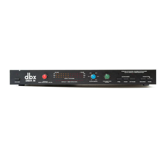
Model 3BX III
Three-Band
Dynamic-Range Expander
with Impact Restoration
SERVICE MANUAL
All dbx products are manufactured under patents in the US and abroad, and on all
dbx circuit designs dbx holds copyright in one or more of the following years:
1979-'85.
"dbx" is a registered trademark of dbx, Newton, Mass. USA.
Advertisement
Chapters
Table of Contents

Related Manuals for dbx 3BX III

Summary of Contents for dbx 3BX III
- Page 1 Dynamic-Range Expander with Impact Restoration SERVICE MANUAL All dbx products are manufactured under patents in the US and abroad, and on all dbx circuit designs dbx holds copyright in one or more of the following years: 1979-’85. “dbx” is a registered trademark of dbx, Newton, Mass. USA.
-
Page 3: Table Of Contents
2. INSPECTION and WARMUP ........9 3. POWER-SUPPLY TESTS .......... 9 4. CONTROL-CIRCUITRY TESTS ........9 5. VCA-SYMMETRY ADJUSTMENTS ........12 6. VCA-GAIN ADJUSTMENTS ........13 7. PERFORMANCE TESTS .......... 14 MODEL 3BX III PRINTED CIRCUIT BOARD ASSEMBLY....20 MODEL 3BX III MAIN ASSEMBLY........25... -
Page 4: Specifications (Performance Minimums)
IMD is measured with 19 kHz and 20 kHz mixed 1:1; output 1 V. 6) Inputs and outputs have identical polarity. 7) All dbx home products are designed to be used with components whose output impedance is less than or equal to 5 k-ohms. -
Page 5: Circuit Description
Model 3BX III Service Manual CIRCUIT DESCRIPTION SCHEMATIC CONVENTIONS The 3BX III is a stereo unit, with two independent, identical signal paths. We will refer here to the left channel only (channel 1). Almost all of its components are identified by designations ending in L (e.g., C705L, R708L);... - Page 6 3 voltage will not cause any variations in the dc level at the output of a VCA, but in the 3BX III, symmetry adjustments (VR701L for the low band, VR702L for the mid, VR703L for the high) are provided to compensate for non-ideal performance.
-
Page 7: Control-Voltage (Cv) Path
Finally, the signal passes to the switching circuitry. The switching allows the 3BX III signal path (a) to come either before or after a tape deck plugged into the tape jacks of the 3BX III, (b) to receive its signal from either the tape deck or the source, and (c) to bypass the circuitry. - Page 8 Model 3BX III Service Manual The output of these ICs (pin 7) is a dc voltage proportional to the dB signal level at the output of the filter that feeds them. TP9 is the low-band output, TP11 the mid-band, and TP13 the high-band.
-
Page 9: High-Band Cv Path
Model 3BX III Service Manual The rms-detector outputs connect to inverting buffer stages (2/2-U710, 2/2-U711, and 2/2-U722) with gains of 9. At these buffers, individual dc voltages from trim pots VR705, VR707 and VR709 are added to the rms- detector output voltages, and a single dc voltage from the Transition- Level control (VR710 on the front panel) is added to all three stages. - Page 10 Model 3BX III Service Manual All photos: All front controls @ maximum; Rear trim (Impact Release Rate) centred a & b photos: c photos; 300 Hz tone-burst @ 316 mV rms (447 mV peak), 3 kHz tone-burst @ 316 mV rms (447 mV peak), 128 cycles on, 172 cycles off, 0.2 s/div...
-
Page 11: Low-Band Cv Path
Model 3BX III Service Manual Finally, the output of the impact-disable circuit connects to the summer stage (2/2-U719) previously mentioned, where both the expansion and impact-restoration CVs are combined before being sent to the VCA. Trim pots (VR721 and VR722) are provided at the output of this summer to allow... -
Page 12: Power Supply And Mute Generator
Model 3BX III Service Manual In the LED display, current sources (QL01 through QL08) of approximately 7 mA each provide constant currents to each series-connected string of six LEDs regardless of the number of LEDs on at any one time. -
Page 13: Alignment Procedure
Model 3BX III Service Manual ALIGNMENT PROCEDURE INPUTS OUTPUTS 1. INSTRUMENTS REQUIRED Audio-frequency sine-wave oscillator with 50 ohm output impedance (Kron- Hite 4200A or equivalent) 10 MHz oscilloscope capable of 2 mV/div sensitivity (Philips PM 3233 or equivalent) DC voltmeter capable of accurately measuring 1 mV (digital preferred,... - Page 14 Model 3BX III Service Manual 4.1.2 Connect the sine-wave oscillator to both inputs of the unit under test. Set it to 20 Hz and an output level of +10 dBV (3.16 V). Connect the scope to the output of the low-band rms- detector buffer at TP10 (U710, pin 7) and set it to 2 mV/div (AC- coupled) and 10 ms/div.
-
Page 15: Reduce The Oscillator's Output Level In 10 Db Steps And
Model 3BX III Service Manual 4.2 Mid-band rms calibration 4.2.1 Set the controls as in 4.1.1. 4.2.2 Connect the sine-wave oscillator to both inputs. Set it to 100 Hz, +10 dBV (3.16 V). Connect the scope to the output of the mid-band rms-detector buffer at TP12 (U711 pin 7) and set it to 5 mV/div (AC-coupled) and 2 ms/div. -
Page 16: Vca-Symmetry Adjustments
5.1.2 Short the main inputs to ground and connect a sine-wave oscillator to TP3 (U706L, pin 3). Set the oscillator for 100 Hz, 100 mV rms. 5.1.3 Connect the scope to the 3BX III left-channel output. vertical sensitivity 20 mV/div horizontal 2 ms/div. -
Page 17: Vca-Gain Adjustments
6.3 Left-Channel Adjustment 6.3.1 Set the oscillator for 100 Hz at 0 dBV (1 V rms) ±0.1 dB. 6.3.2 Connect the left-channel output of the 3BX III to an AC voltmeter. 6.3.3 Adjust VR717 for unity gain, i.e., an output of 0 dBV (1 V rms) ±0.1 dB. -
Page 18: Performance Tests
3BX III. 7.1.3 Connect the oscilloscope to the output of one channel of the 3BX III. Connect the scope sweep-trigger input to the gate or trigger output on the tone-burst oscillator. - Page 19 Model 3BX III Service Manual 7.1.5.2 Observe the output on the scope. Verify that the wave shape is substantially as shown in Fig. 9b, and confirm for the other channel. Figure 9b 7.1.5.3 Observe that the Impact display lights at least 10 out of the 12 LEDs.
- Page 20 Model 3BX III Service Manual 7.2 Expansion Magnitude and Timing 7.2.1 Set the unit as follows: Expansion Maximum Impact Restoration Minimum Transition Level Middle Pre/Post Source/Tape Source Bypass Out (i.e., not set) 7.2.2 Connect the oscillator and tone-burst generator as in 7.1.2 and 7.1.3 above.
- Page 21 Model 3BX III Service Manual Figure 10b 7.2.4.3 Observe that the mid-band display lights at least to the 4 red LED during the burst and returns to the 1 red LED between bursts. 7.2.5 High-Band Test 7.2.5.1 sine-wave oscillator tone-burst generator as in 7.1.6.1.
- Page 22 3BX III output. 7.3.4.3 Reduce the oscillator output to –10 dBV (316 mV rms). 7.3.4.4 Verify that the 3BX III output level decreases to -15 dBV (178 mV rms) ±1 dB. 7.3.4.5 Reduce the oscillator output to –20 dBV (100 mV rms).
- Page 23 (RCA, or phono [pin], plugs with 1 k resistor terminations are ideal). 7.5.3 Connect one channel output of the 3BX III to the input of the rms-responding AC voltmeter. 7.5.4 Verify that the noise level is less than –85 dBV unweighted or –90 dBV A-weighted.
-
Page 24: Model 3Bx Iii Printed Circuit Board Assembly
Model 3BX III Service Manual MODEL 3BX III PRINTED CIRCUIT BOARD ASSEMBLY REFERENCE DESCRIPTION PRODUCT CODE DBX P/N QTY. DESIGNATION LED CONNECTOR CORD ASSEMBLY, M” LEADS 510ACCNL31ULA 310472 POWER LED CONNECTOR CORD ASSEMBLY SIOACC9L7SULA 320215 CONNECTOR RED, ASSEMBLY 510ACZZ243CFA 320216... - Page 25 Model 3BX III Service Manual REFERENCE DESCRIPTION PRODUCT CODE DBX P/N QTY. DESIGNATION D701-727, 807 SILICON DIODE MA150, OR 1N4148 510QDSMA150XN 140031 D805, 806 SILICON DIODE SR1K-4LF OR 1N4003 510QDSSR1K4AP 140022 D801, SILICON DIODE W02M 5l0QDSW02MXXG 140008 U712, 720 IC, OP-AMP, LM301AN...
- Page 26 Model 3BX III Service Manual REFERENCE DESCRIPTION PRODUCT CODE DBX P/N QTY. DESIGNATION R751 RESISTOR, CARBON FILM 1/4W 1.5M ohm 5% 51ORD2SPJISSX 054155 RL02, L14, RESISTOR, CARBON FILM 1/4W 1.6K ohm 5% 51ORD25PJ162X 054162 L24, L36, L46, L58, L68, L77...
- Page 27 Model 3BX III Service Manual REFERENCE DESCRIPTION PRODUCT CODE DBX P/N QTY. DESIGNATION R761 RESISTOR, CARBON FILM 1/4W 390K ohm 5% 51ORD2SPJ394X 054394 RL22, L44, L66 RESISTOR, CARBON FILM 1/4W 430K ohm 5% SIORD25PJ434X 054434 718L, 718R, RESISTOR, CARBON FILM 1/4W 47 ohm 5%...
- Page 28 Model 3BX III Service Manual REFERENCE DESCRIPTION PRODUCT CODE DBX P/N QTY. DESIGNATION ZZ703 THERMALLY CONDUCTIVE TRANSISTOR INSULATOR 510VS223RH002 310417 WIRE JUMPER, 22 AWG, YELLOW 310184 WIRE JUMPER, 22 AWG, GREEN 310183 WIRE JUMPER, 22 AWG, BLUE 310185 WIRE JUMPER, 22 AWG, GREY...
-
Page 29: Model 3Bx Iii Main Assembly
Model 3BX III Service Manual MODEL 3BX III MAIN ASSEMBLY REFERENCE DESCRIPTION PRODUCT CODE DBX PM DESIGNATION ESCUTCHEON 510ME9SEAA024 290693 BUTTON/LED GUIDE 510VF132SBOO4 210213 2, 3, 4 VR KNOB ASSEMBLY 510AVKNOB*175 380211 PAN HEAD RIVET M3 x 4.5 QCK NYLON-B... - Page 30 Model 3BX III Service Manual SCHEMATIC – 26 –...
- Page 31 Model 3BX III Service Manual CIRCUIT BOARD, COMPONENT SIDE (TOP) – 27 –...
- Page 32 Model 3BX III Service Manual CIRCUIT BOARD, NON-COMPONENT SIDE (BOTTOM) – 28 –...
- Page 33 Model 3BX III Service Manual LED SCHEMATIC, PCB, PINOUTS – 29 –...
- Page 34 Model 3BX III Service Manual MECHANICAL ASSEMBLY, EXPLODED VIEW – 30 –...
- Page 35 Model 3BX III Service Manual NOTES Miscellaneous notes on servicing the dbx 3bx III Audio Expander =============================================================== Removing the control knobs -------------------------- Remove the case top. Unplug the 5 LED connectors from the right hand side of the front panel.
- Page 36 Model 3BX III Service Manual NOTES – 32 –...
- Page 37 3853C-600307 Printed in USA...