Table of Contents
Advertisement
Quick Links
Advertisement
Table of Contents

Related Manuals for NDC BenchMike Pro 2025


Summary of Contents for NDC BenchMike Pro 2025
- Page 1 BenchMike Pro Benchtop Laser Micrometer Instruction Handbook NDC Technologies Main Phone +1 (937) 233-9935 8001 Technology Blvd. General Fax +1 (937) 233-7284 Dayton, Ohio 45424 www.ndc.com/betalasermike U.S.A. © BETA LaserMike Products 2019 NDC Technologies © 2017 NDC TechnologiesNDC...
- Page 2 Proprietary Notice The information and design disclosed herein were originated by and are the property of NDC Technologies. NDC Technologies reserves all patent, proprietary design, manufacturing, reproduction use, and sales rights thereto, and to any article disclosed therein, except to the extent rights are expressly granted to others. The fore- going does not apply to vendor proprietary parts.
- Page 3 Contact NDC Online Support You can access the NDC Customer Support portal, myNDC at https://ndc.custhelp.com. myNDC is a cloud-based portal that allows you to get product support by phone, ask a question, provide feed- back, submit an RMA request or access information in our on-line knowledge database. You can browse the myNDC site or create a myNDC account.
- Page 5 NDC Contact Numbers by Product Type Please have your sales order number at hand before contacting NDC. − NDC Systems including Infrared, Xray and Nucleonic Sensors NDC Systems: including Infrared, Xray and Nucleonic Sensors Americas +1 626 939 3855 Japan: +81 (0)3 3255 8157...
- Page 6 All other countries (English speaking): Africa) +44 1621 852244 Please select option 3 to be connected to the service team − NDC Metals Systems, including AccuRay and IRM brands NDC Metals Systems: including AccuRay and IRM brands North America: +1 626 939 3855 Americas...
- Page 7 Caution • This equipment must be earthed/grounded. • Under NO circumstances should the earth safety connections be broken – internal damage to sensi- tive electronic components may occur and at worst electrocution to personnel may result. • Digital outputs are open - collector outputs, with max- imum specs of 35 V DC and 250ma.
- Page 8 Labels and Safety Features This section acquaints you with the advisory and identification labels on the instrument and the safety features incorporated into the design of the instrument. The following figures show the identification and advisory labels on the BenchMike Pro. Front View Scanning laser beam...
- Page 9 Model 2050 LASER SAFETY LABEL SERIAL TAG USB-A PRINTER USB-B SERIAL DB-9 FEMALE ETHERNET SERIAL 1 DB-25 FEMALE FIXTURE DB-25 MALE I/O FCC Manual Digital Devices Statement NOTE: This equipment has been tested and found to comply with the limits for a Class A digital device, pursuant to part 15 of the FCC Rules.
-
Page 10: Table Of Contents
Table of Contents INTRODUCTION ..........................1-1 1.1 I ........................... 1-1 NTRODUCTION 1.2 B ......................1-1 ENCH PTIONS 1.2.1 Laser Beam Options ......................1-1 1.2.2 Interfaces ......................... 1-1 1.2.3 Accessories ........................1-1 1.2.4 Measurement Fixtures ..................... 1-2 1.3 C ..........................1-2 ALIBRATION 1.4 U ...................... - Page 11 2.3.4 Connecting to Digital Outputs with the BenchMike Pro +12V Supply ......2-9 2.3.5 Connecting to Digital Outputs with an External Supply ..........2-10 2.3.6 Serial Connector ......................2-10 2.3.7 USB Printer Connector ....................2-11 2.3.8 USB Serial Connector ....................2-11 2.3.9 Ethernet RJ45 Connector ....................
- Page 12 4.8 S ......................4-16 ETTINGS UNCTIONS 4.9 R ..........................4-17 EPORTS 4.9.1 Sample Report ....................... 4-18 4.9.2 Batch Report ........................4-19 4.9.3 Fixture Sample Report ....................4-20 4.9.4 Fixture Batch Report ...................... 4-21 4.9.5 Rotating Fixture Batch Report Data Flow ..............4-22 4.9.6 Serial Data Out Format ....................
- Page 13 5.1 E ......................... 5-1 XPRESSION DITOR 5.1.1 Components of the Expressions ..................5-1 5.2 A ....................5-6 DVANCED CREEN APABILITIES 5.2.1 Accessing Advanced Capabilities ................... 5-6 5.2.2 Tolerance and Limit Checking Display Capabilities ............5-7 5.3 C ......................5-8 USTOM EASUREMENTS 5.3.1 Custom Measurement Properties ..................
-
Page 15: Introduction
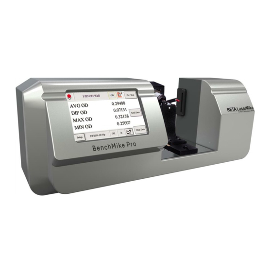
CHAPTER Introduction Introduction This manual contains detailed information about the NDC Technologies BenchMike Pro Benchtop Laser Microme- ters. This includes the following two models: • BenchMike Pro Model 2025 • BenchMike Pro Model 2050 BenchMike Pro Options The Model 2025 BenchMike Pro covers the measurement range 0.003-1.00 inch, and the Model 2050 BenchMike Pro covers the measurement range 0.010-2.00 in. -
Page 16: Measurement Fixtures
In order to ensure the measurement accuracy shown in the Specifications, it is recommended that you have your BenchMike Pro calibrated by NDC Technologies once per year. While at the factory, NDC Technologies can also perform any required retrofits, repairs, or upgrades. -
Page 17: Using The Benchmike Pro
Using the BenchMike Pro To turn on the BenchMike Pro, push the power button on the rear of the unit. It will take about one minute for the unit to initialize. To turn off the BenchMike Pro, push the power button for one second. The BenchMike Pro will begin the power-down cycle. -
Page 18: Sources Of Error
The measurement area surrounds the Pass Line of the gauge and covers of the full measurement range of the unit (1.0 in. for the Model 2025 and 2.0 in. for the Model 2050). The Pass Line of the gauge is located halfway between the transmitter and the receiver. -
Page 19: Measuring Transparent Products
1.5.2 Measuring Transparent Products Transparent product The BenchMike Pro can measure transparent products when a Transparent Object Measurement type (Types 51, 52, and 53) is selected. See section in Setup about Measurement Types for more information. Although an opaque product blocks laser light across its en- tire diameter, a transparent product allows some laser light to pass through. -
Page 20: Data Processing And Display
Data Processing and Display The BenchMike Pro allows you great flexibility in controlling the way data is displayed and processed. As de- scribed in the Advanced Capabilities section, there are several parameters which can be used to control the aver- aging of measurements, the number of digits displayed on the screen, the format of printed reports, etc. -
Page 21: Laser Safety
Warning Information The BenchMike Pro is equipped with a warning label as a reminder that a laser is present during operation. If a problem occurs with the operation of the BenchMike Pro, contact NDC Technologies Customer Service im- mediately. Only trained NDC Technologies service personnel should perform service operations on this product. The use of controls or adjustments or the performance of procedures other than those specified in this manual may result in hazardous radiation exposure. -
Page 23: Installation
CHAPTER Installation Instructions 2.1.1 Power To power the BenchMike Pro, use the supplied, detachable mains supply cord. Using an under-rated or not- certified power cord is a safety hazard. Only power cords with the appropriate ratings for the country of use and with a rating of 5 amps or greater should be used. -
Page 24: Caution Symbol
This product should only be used or serviced by trained NDC Technologies personnel. Failure to do so could result in physical injury, damage to the product, and/or voiding of the warranty. If you have any questions or problems, please contact the NDC Technolo- gies Customer Service Department. -
Page 25: Benchmike Pro Model 2025 Outline Drawing
2.2.1 BenchMike Pro Model 2025 Outline Drawing NOTE: Dimensions are in millimeters (inches). NOTE: mount the universal mounting plate with the -10 in the lower left corner (as seen looking downward from the operator’s position) of the BenchMike Pro’s measurement area. BenchMike Pro Instruction Handbook: Installation... -
Page 26: Benchmike Pro Model 2025 Connector Drawing
2.2.2 BenchMike Pro Model 2025 Connector Drawing LASER SAFETY LABEL PASSLINE SERIAL TAG HEIGHT SCAN CENTER ETHERNET DB-9 FEMALE USB-A FEMALE PRINTER SERIAL 1 USB-B FEMALE SERIAL USB DB-25 MALE I/O DB-25 FEMALE FIXTURE BenchMike Pro Instruction Handbook: Installation... -
Page 27: Benchmike Pro Model 2050 Outline Drawing
2.2.3 BenchMike Pro Model 2050 Outline Drawing NOTE: Dimensions are in millimeters (inches). NOTE: Mount the universal mounting plate with the -20 in the lower left corner (as seen looking downward from the operator’s position) of the BenchMike Pro’s measurement area. BenchMike Pro Instruction Handbook: Installation... -
Page 28: Benchmike Pro Model 2050 Connector Drawing
2.2.4 BenchMike Pro Model 2050 Connector Drawing LASER SAFETY LABEL PASSLINE SERIAL TAG HEIGHT SCAN CENTER ETHERNET RJ 45 SOCKET DB-9 FEMALE USB-A FEMALE PRINTER SERIAL 1 USB-B FEMALE SERIAL USB DB-25 MALE I/O DB-25 FEMALE FIXTURE BenchMike Pro Instruction Handbook: Installation... -
Page 29: Connections
Connections 2.3.1 Connecting the BenchMike Pro to Your PC Use the BenchMike Pro’s serial port, labeled Serial #1, to connect your PC to the BenchMike Pro. The cable used to connect the BenchMike Pro and PC should be a shielded, straight-through cable with a DB-9 female connector on one end and a DB-9 male connector on the other end. - Page 30 Alarm #4 (-Reject) Alarm #3 (-Warning) Alarm #2 (+Warning) Alarm #1 (+Reject) +5 Volts Signal ground Signal ground N. C. N.C. Alarm 11* Alarm 12* Alarm 10 Alarm 9 Signal ground Alarm 8 Alarm 7 Alarm 6 Alarm 5 +12 Volts * Non-sequential order is intentional.
-
Page 31: Connecting To Digital Inputs
2.3.3 Connecting to Digital Inputs Consult the diagram below to connect digital inputs to your BenchMike Pro. See the description of system functions for software configuration of digital inputs for details. 2.3.4 Connecting to Digital Outputs with the BenchMike Pro +12V Supply Consult the diagram below to connect digital outputs via the BenchMike Pro’s +12 V supply. -
Page 32: Connecting To Digital Outputs With An External Supply
2.3.5 Connecting to Digital Outputs with an External Supply Consult the diagram below to connect digital outputs via an external supply. See the description of the system functions for software configuration of digital outputs for details. 2.3.6 Serial Connector The BenchMike Pro has one standard serial port. This port supports RS232 interfaces and baud rates up to 38.4 Kbaud. -
Page 33: Usb Printer Connector
2.3.7 USB Printer Connector The USB A connector is for a CUPS-compatible printer. 2.3.8 USB Serial Connector The USB B simulates a serial port when connected to a P.C. 2.3.9 Ethernet RJ45 Connector The Ethernet connection uses a telnet connection to send and receive PURL commands and send data. 2.3.10 Fixture Connector The fixture connector offers two four-bit output ports capable of driving a four-phase stepper motor. -
Page 34: Connecting To A Quadrature Encoder
C-SDA Serial data line C-SCK Clock Digital input #5 Digital input #6 Digital input #7 Digital input #8 Signal ground Quad encoder #1 input A Quad encoder #1 input B Quad encoder #2 input A Quad encoder #2 input B +12 V 2.3.11 Connecting to a Quadrature Encoder... -
Page 35: Adding A Network Printer
Adding a Network Printer 2.4.1 Requirements The following requirements must be met to allow the BenchMike Pro to print to a network-attached printer: • The BenchMike Pro must be able to access the printer via Ethernet. • The operator must have a PC with a web browser attached to the same network as the BenchMike Pro. •... - Page 36 3. Define the Benchmike Pro Ethernet Settings, e.g., 10.32.0.65 (again, the same network). Ensure that the Use DHCP box is checked. Restart the Benchmike Pro to ensure that the IP address is set correctly. 4. Connect via the web browser to address: https://10.32.0.65:631/admin/ , where 10.32.0.65 is the Bench- mike Pro IP address.
- Page 37 Alternately, you may encounter a different network warning when attempting to add the printer. This warning may be bypassed by clicking on the Advanced button. then clicking the Add Exception button. Finally, click the Confirm Security Exception button. BenchMike Pro Instruction Handbook: Installation 2-15...
- Page 38 6. The printer CUPS server will appear as shown. 7. Select Add Printer 8. There are two options for you to select the desired printer. If your printer appears in the Discovered Network Printers list, select the appropriate printer. If not, but if you know the IP address, select the Internet Printing Protocol (ipp) option.
- Page 39 9. If you selected Internet Printing Protocol (ipp), a screen will appear to allow you to enter the IP address of your printer. Enter the address in the format shown in the image below, then click Continue. If your printer was in the list of Discovered Network Printers, skip to the next step.
- Page 40 11. Select a Make of Raw, then select Add printer. 2-18 BenchMike Pro Instruction Handbook: Installation...
- Page 41 12. Select Raw Queue (en) and then Add Printer. 13. Select “retry-job” for the Error Policy. Then click the “Set Default Options” button at the bottom of the page. BenchMike Pro Instruction Handbook: Installation 2-19...
- Page 42 14. Select the desired printer. 15. Select Administration option and on pull down menu, select Set As Server Default 16. A confirmation message will appear as shown. 17. From the Benchmike Pro, select Save and then cycle power to the unit. 2-20 BenchMike Pro Instruction Handbook: Installation...
- Page 43 18. After the Benchmike Pro has rebooted, verify that the printer output has been set correctly. If not, repeat this procedure. 19. Go to Report Setup, and then the Output tab. Also select the type of report to output and test. BenchMike Pro Instruction Handbook: Installation 2-21...
- Page 44 20. Verify the report. 2-22 BenchMike Pro Instruction Handbook: Installation...
-
Page 45: Adding Ausb Printer
Adding a USB Printer 2.5.1 Requirements The following are required to allow the unit to print to a USB printer: • A USB printer must be plugged into the USB A-type connector on the rear of the unit • The operator must have a PC with a web browser attached to the same network as the unit. 2.5.2 Procedure 1. - Page 46 3. Define the Benchmike Pro Ethernet Settings, e.g., 10.32.0.65 (again, the same network). Ensure that the Use DHCP box is checked. Restart the Benchmike Pro to ensure that the IP address is set correctly. 4. Connect via the web browser to address: https://10.32.0.65:631/admin/ , where 10.32.0.65 is the Bench- mike Pro IP address.
- Page 47 Alternately, you may encounter a different network warning when attempting to add the printer. This warning may be bypassed by clicking on the Advanced button. then clicking the Add Exception button. Finally, click the Confirm Security Exception button. BenchMike Pro Instruction Handbook: Installation 2-25...
- Page 48 6. The printer CUPS server will appear as shown. 7. Select the Local Printer that is connected to the USB port. In this example, we use an HP LaserJet 1012 printer. Then press Continue. 2-26 BenchMike Pro Instruction Handbook: Installation...
- Page 49 8. Enter identifying information for the printer as in the example, below, then click Continue. 9. Click the Select Another Make/Manufacturer button. The BenchMike sends printer data as a Raw printer, not for a specific manufacturer driver. BenchMike Pro Instruction Handbook: Installation 2-27...
- Page 50 10. Choose the Raw Make, then click Continue. 2-28 BenchMike Pro Instruction Handbook: Installation...
- Page 51 11. Choose the Raw Queue (en) Model, then click Add Printer. BenchMike Pro Instruction Handbook: Installation 2-29...
- Page 52 12. Select “retry-job” for the Error Policy. Then click the “Set Default Options” button at the bottom of the page. 13. Set the printer as the default by clicking the Set As Server Default option from the Administration drop- down list. 2-30 BenchMike Pro Instruction Handbook: Installation...
-
Page 53: Workholding Fixtures
CHAPTER Workholding Fixtures Error Signals The BenchMike Pro is designed to detect system errors that occur as the result of improper part positioning, faulty keystrokes by the user, or component failure. When an error condition is detected, the BenchMike Pro alerts the operator by displaying an message on the touch screen display. -
Page 54: Intelligent Fixture: Rotary/Linear Fixture Position
Rotary fixtures include the ID/OD/Wall and Belt Drive fixtures. Most NDC Technologies fixtures contain an ID chip. The Intelli- gent Fixture option allows the BenchMike Pro to read this ID chip to identify the name and physical characteristics of the fixture including motor, encoder, gear ratio, end of travel sensor, etc. -
Page 55: Universal Slide Fixture
3.3.1.1 Drawing of Fixed V-Block 3.3.2 Universal Slide Fixture The Universal Slide Fixture is used to linearly position parts by hand. Features include: • Hardened dovetail rail mates with other fixtures, such as the Adjustable Centers and Adjustable V-Blocks • Manual locking knob to lock the slide at a desired position •... - Page 56 3.3.2.1 Drawing of the Universal Slide Features of Adjustable Centers include: • Pair of adjustable male centers that mate with the dovetail rail. One center is lever-operated and spring- loaded for part loading. • Hardened centers • Centers diameter: 15.8 mm (0.625 in.) Slide 18 in.
- Page 57 3.3.2.2 Drawing of the Adjustable Centers mounted on the Universal Slide Features of Adjustable V-Blocks include: • Pair of adjustable V-blocks that mate with the dovetail rail. V height is adjusted by locking knob. Millimeter position scale. • V-block part size range: 2.286-50.8 mm (0.090-2.0 in.) •...
- Page 58 3.3.2.3 Drawing of the Adjustable V-Blocks mounted on the Universal Slide BenchMike Pro Instruction Handbook: Workholding Fixtures...
-
Page 59: Digital Readout (Dro) Slide Fixture
3.3.3 Digital Readout (DRO) Slide Fixture The Digital Readout (DRO) Slide Fixture is used to linearly position parts to predetermined positions for meas- urement and/or to measure the distance between two points on a part. Features include: • Direct readout of position on the BenchMike Pro screen •... - Page 60 3.3.3.1 Drawing of the DRO Slide Features of Adjustable Centers include: • Pair of adjustable male centers that mate with the dovetail rail. One center is lever-operated and spring- loaded for part loading. • Hardened centers • Centers diameter: 15.8 mm (0.625 in.) Slide 18 in.
- Page 61 3.3.3.2 Drawing of the Adjustable Centers mounted on the DRO Slide Features of Adjustable V-Blocks include: • Pair of adjustable V-blocks that mate with the dovetail rail. V height is adjusted by locking knob. Millimeter position scale. • V-block part size range: 2.286-50.8 mm (0.090-2.0 in.) •...
- Page 62 3.3.3.3 Drawing of the Adjustable V-Blocks mounted on the DRO Slide 3-10 BenchMike Pro Instruction Handbook: Workholding Fixtures...
-
Page 63: Setup
CHAPTER Setup Your instrument was carefully inspected electrically and mechanically prior to shipment. It should be free of sur- face mars and scratches, and it should be in perfect working order upon receipt. If any indication of damage is found, file a claim with the carrier immediately, prior to using the instrument. If no damage is apparent, proceed by using this manual to install and setup this instrument. - Page 64 Only four measurement items are displayed at one time, but you can change the order and type of items by simply touching one of the items in the center of the display if you have Advanced Screen options are enabled. If you wish one measurement item to be magnified on the screen to be visible from a distance, select Magnify from the menu, as shown.
- Page 65 Touch the Quick Info block to access these three pages. You can specify the date, the time, and the display set- ting for Quick Info display from these pages. Selecting Flash will display the amount of flash storage available for library settings. Selecting RAM will display the amount of memory available to the software application.
-
Page 66: Mode Icon And Menu
Mode Icon and Menu Note that the Mode icon changes based on the measurement mode in operation. This icon indicates that measurements are not being taken and the BenchMike Pro has detected the correct number of part edges or segments. This icon pulsates at the measurement update rate, indicating that measurements are being taken. -
Page 67: Feature Icon
When the Send command line is selected, the current measurements that have been selected for serial output are transmitted via serial port #1 and serial USB, both located on the rear panel of the BenchMike Pro. This func- tion can also be performed by pressing the Send Data data button on the front of the BenchMike Pro. To allow data to be transmitted open the Setup->System->Communications Ports, under the Assignment tab, select the Allow Measurement Data to be Sent option. -
Page 68: Measurement Icon
Measurement Icon Touch the Measurement Setup icon in the upper right hand corner of the screen to display the menu shown. This icon allows you to quickly access the settings for measurement parameters. Note that you can access these same screens by selecting Set- up, then Measure, then Measurement. -
Page 69: Setup Menu
Setup Menu Touch the Setup icon in the lower left hand corner of the screen to display the menu shown. From this menu you can access all setup functions of the BenchMike Pro. Note that the order of options shown here indicates the hier- archical order of the commands. - Page 70 The information received via the Digital Inputs port of the BenchMike Pro is defined via the Digital Inputs page. The trigger for each input can be set to: NO, NC, or Toggled. Each of the inputs can be defined separately. These inputs are: •...
- Page 71 The Display Setup page allows you calibrate the touch screen. The Fixture Menu allows you to define the physical attrib- utes of a custom fixture. Note that some fixtures appear to the BenchMike Pro to be two fixtures (as shown), typically as a fixture for each axis of measurement.
- Page 72 Ten configuration menus will appear. If you are not using an Intelligent Fixture, you will be able to enter and de- fine the type of fixture to be used. Note that you can enter the name and functions of the fixture and store the val- ues under that name for future use.
-
Page 73: Communication Ports
Encoder 1 tab Encoder 2 tab Home Sensor tab EOT Sensor tab 4.6.1 Communication Ports The communication ports are a standard feature. The Communication Port Setup menus offer three tabs to cus- tomize the port for data transmission for serial port #1, serial USB, and Ethernet. - Page 74 If you select Serial port #1 or Serial USB, the following three tabs will appear. The Configuration tab shown to the right allows you to select various communication features such as the baud rate and par- ity. The Flow tab appoints the method in which data flow is con- trolled.
-
Page 75: Sleep And Shutdown Functions
On the DNS tab, the Primary DNS Address and Secondary DNS Address can be changed. The Assignment tab offers options to enable/disable Program- mable Universal Resource Language (PURL) commands. These commands are used to for remote control and programming of the BenchMike Pro. -
Page 76: Library Functions
Library Functions NOTE: Library commands are unique to each library but are common to all the features within a library. The use of libraries allows you to store and recall, how the measurements are to be taken, and other system setup infor- mation into separate libraries. - Page 77 When you select Print, values for the currently active library will be sent as directed by the Reports Output setting. NOTE: If the BenchMike Pro is turned off prior to saving the active library, all changes will be lost. When you choose Save, a menu is displayed which asks you to confirm that you wish to save the changes you have made to the active library.
-
Page 78: Settings Functions
Settings Functions Touch Settings from the Setup menu to display the menu shown. This menu contains settings that are unique to each library. NOTE: Settings commands are unique to each library but are common to all features within a library. To access settings for printed reports, select Setup, then Settings, and then Reports. -
Page 79: Reports
Reports The key difference between Batch and Sample Reports is that Sample Reports can only be printed one time per sample, while Batch Reports can be printed multiple times by pressing the Print key. Sample and Batch Reports contain data from a single part measurement. If Continuous measurements are selected for Sample and Batch Reports (under the Measurement Setup Type tab), measurements will be taken until the Print key is touched or until the Reading Count equals the Batch Count value. -
Page 80: Sample Report
4.9.1 Sample Report The Sample Report is designed for use when taking a single measurement of multiple parts. NOTE: A maximum of 31 characters is permitted in the Title (shown as “Your Information Here”) line. NOTE: The headers are optional and can be turned on and off on the Report Setup/Output page. NOTE: This report is printed for each Feature that has been inserted in the library, causing the Feature number to be added to the report header. -
Page 81: Batch Report
4.9.2 Batch Report The Batch Report is a companion report to the Sample Report shown on the previous page. It summarizes the statistical results for all the measured parts, as shown in the example below. NOTE: A maximum of 31 characters is permitted in the Title (shown as “Your Information Here”) line. NOTE: The headers are optional and can be turned on and off on the Report Setup/Output page. -
Page 82: Fixture Sample Report
4.9.3 Fixture Sample Report The Fixture Sample Report is designed for use with automated part positioning fixtures, such as the Auto-Rotating Chuck Fixture. This report is automatically printed one time at the end of the fixture measurement cycle. Note that there is no header for this report. -
Page 83: Fixture Batch Report
4.9.4 Fixture Batch Report The Fixture Batch Report is a companion report to the Fixture Sample Report shown on the previous page. It summarizes the statistical results for all the measured parts. NOTE: A maximum of 31 characters is permitted in the Title (shown as “Your Information Here”) line. Your Information Here Fixture Batch Report Library 03/Untitled/F01... -
Page 84: Rotating Fixture Batch Report Data Flow
4.9.5 Rotating Fixture Batch Report Data Flow Individual Individual Readings Part/Sample NOTE: 0.033350 Summaries Oversize and un- 0.033390 0.03413 0.033550 0.03333 dersize samples 0.033950 0.03365 values are based 0.034000 Std dev 0.000325 on sample averag- 0.034130 Range 0.00080 0.033490 0.033330 0.033390 0.033340 0.03410... -
Page 85: Serial Data Out Format
4.9.6 Serial Data Out Format The Serial Data Out Format menu also accesses the Data Format, Data Flow, and Number Format tabs, which allow the format of serial output to be easily changed. Many data values can be transmitted through the serial ports, as listed below: NOTE: Serial output data values are selected from the Setup - Data... -
Page 86: Sqc Batch Setup
This screen allows you to display a +/- sign in front of numerical values sent through the serial port. If not selected, only negative numbers will include a sign. Note that the second option is used to change the format of sent data. When checked, a period will be used to indicate a decimal point in the data. -
Page 87: Units/Res/Rounding
The Optical Plate Compensation Setup tab shows the optical plate temperature. This is a “read only” value from a sensor on the optical plate. The CPU temperature is a “read only” value of the temperature of the computer inside the BenchMike Pro. 4.9.9 Units/Res/Rounding The Units screen is used to define the measurement units dis-... -
Page 88: Feature Functions
4.10 Feature Functions Features are similar to libraries, in that settings can be saved and stored for repeated use. However, features are different from libraries in that they permit you to develop more complex setups for your applications. Features allow you to link data between one another, unlike libraries, which function inde- pendently. - Page 89 The Delete function deletes the current feature. You will be asked to confirm that you wish to delete the feature. Shortcut: Touch the Feature number (shown here as F01) to display this screen. You can create a new feature with the Insert New function. By default, the new feature will be created in the current library, following the current feature.
-
Page 90: Measurement Functions
4.11 Measurement Functions By selecting the Measurement option, you can define ex- pressions, settings for fixtures, measurement types, nomi- nal/limit/tolerance settings, the floating nominal value, and a user master value. When multiple Features exist, measure- ment settings are unique to each. NOTE: Measurement commands are unique to each feature within each library. - Page 91 Auto positioning fixtures The fixture used for auto positioning is a slave to the fixture which is collecting data. The fixture will move between taking measurements. This option is enabled if both attached fixtures are motorized. Measurement is initiated by the Go command.
- Page 92 Two-fixture movement When two fixtures are selected for movement, the Manual option is not available for selection. The fixture that collects measurement data is the Collection Fixture, and the fixture that moves the product into position is the Po- sitioning Fixture. When the Collection Fixture is configured for Automatic movement –...
- Page 93 The Feature position movement mode of the Positioning Fix- ture can be used to measure different positions in a part. In this mode, the Collection Fixture is subordinate to the Posi- tioning Fixture. The Positioning Fixture will move to the loca- tion specified in the feature, and then the complete movement of Collection Fixture will take place.
-
Page 94: Measurement Type
4.11.3 Measurement Type Eighteen measurement types are available. Options include simple diameter measurement, measurements of multiple parts, or measurements of transparent products. All available measurement types are shown below. Each time the laser beam passes over the product, the BenchMike Pro records the product size as a scan. For greater accuracy, the BenchMike Pro groups these scans together to compute a reading. - Page 95 Name Description Diameter Diameter of product Type 1 Diameter of lower product (2 products in beam) Type 2 Distance between 2 products Type 3 Diameter of upper product (2 products in beam) Type 4 Distance from lower edge, lower product to lower edge, upper product Type 5 Distance from upper edge, upper product to upper edge, lower product Type 6...
-
Page 96: Measurement Method
4.11.4 Measurement Method There are three options for Measurement Method: Single measurements, Continuous measurements, and Moving Average. • When Single measurements are selected, the BenchMike Pro will take one reading and then stop. • When Continuous measurements are selected, the BenchMike Pro will take multiple readings until stopped by the user. -
Page 97: Nominal/Limits/Tolerance Setup
4.11.7 Nominal/Limits/Tolerance Set- These two pages for Nominal/Limits/Tolerances Setup allow you to indicate acceptable deviation of the actual product from the desired product size. When these limits are exceeded, all the following are triggered: audible alarm, alarm digital output, and alarm indication on Main Measurement page. NOTE: Upper or Lower Warning and Reject Limits can be se- lected to be displayed on the main measurement screen. -
Page 98: Master Measurement
4.11.9 Master Measurement The Master Measurement function allows you to ensure that your products match your pre-defined master size. This func- tion creates a positive or negative offset to the size that equals the difference between the measured size and the size entered during mastering. -
Page 99: Data Functions
4.12 Data Functions Select the Data option from the menu to specify a variety of op- tions related to the display of measurement data. If you have purchased a fixture, the words Fixture Position op- tion will appear as shown. You can select Deviation, Nominal, Limits, and Tolerance values from this menu so that you can view them on the main page. - Page 100 The Limits option allows you to specify which (if any) of the Warning and Reject Limits are displayed on the main meas- urement display page or are transmitted to the serial port. Posi- tive and Negative and Reject and Warning Limits can be turned on and off individually.
- Page 101 The Part Position displays the vertical part position. Part Po- sition is the position of the part relative to the vertical center of the scan. A positive value indicates that the part is above the centerline, and a negative value indicates that the part is be- low the centerline.
- Page 102 The SQC Setup menus for each of the SQC parameters are identical except for the title. Use these pages to change the label of the parameter or change its location on the main measurement page. You can also decide to transmit these values through the serial output.
-
Page 103: Save Function
The Actual Pressure displays the pressure as read by the hardware. When Barometric Compensation is enabled, this value affects the measurement. The Barometric Temperature displays the barometric temper- ature as read by the hardware. When Barometric Compensa- tion is enabled, this value affects the measurement. 4.13 Save Function You can save your changes to memory by selecting Setup... -
Page 104: Status Menus
Data calculation cannot keep up with gauge’s data rate No Scan No gauge start or stop pulse detected in 500 milliseconds. Factory Calibration Required Contact NDC Technologies Customer Service. Message Description High Reject Product size exceeds Positive Reject Limit value... - Page 105 The Configure button allows you to control system parame- ters such as security, user interface settings, and scanner configuration. Revision information about a NDC Technologies Intelligent Fixture is also available from the Fixture tab, if an Intelligent Fixture is in use.
- Page 106 Note that tabs for international operation, installed options, scanner information, and fixture information are also displayed here. 4-44 BenchMike Pro Instruction Handbook: Setup...
-
Page 107: Security Setup
4.15 Security Setup The BenchMike Pro Security features allow the unit set up to be password protected. The unit can be locked on power up. When the unit is locked, you have the option of permitting or preventing library, limit, nominal, or mas- ter information changes. -
Page 108: Entering The System Password
4.15.1 Entering the System Pass- word When you choose Yes, you will be asked to enter the pass- word. The default password is 000000. NOTE: To toggle between upper case and lower case let- ters, press the Up arrow button. 4.15.2 Security Page The Configuration screen will appear. -
Page 109: Screen Configuration
From these three pages, you can send and receive infor- mation about the configuration of the BenchMike Pro’s scan- ner settings. This information is typically only used by NDC Technologies Service personnel. The data can be sent or received via the serial ports. The data is in ASCII format and can be saved on a PC. -
Page 110: Scan Errors Configuration
From this page you can select UK English, US English, French, German, or Spanish for all spelling, date, and num- ber formats. Other international language support is availa- ble. Contact NDC Technologies for details. 4.15.8 Options 1: Reports This page allows you to enable or disable report options. -
Page 111: Options 2: Graphs
4.15.9 Options 2: Graphs This page allows you to enable or disable two graph options. Note that these graph pages will only operate during meas- urement when a rotating fixture is connected or configured for use. When setup is complete, press the OK button to ac- cept changes. -
Page 113: Advanced Capabilities
CHAPTER Advanced Capabilities Expression Editor The Expression Editor allows you to compute values based on data collected by the BenchMike Pro. Each expression you define is linked to the Feature in which it is created. As shown on the screen to the right, you can copy, cut, edit, delete, insert, paste, move, and restore the expression from factory defaults. - Page 114 Precedence Operator Description 8 (highest) ( or ) Parenthetical expression + or - Unary plus and minus (for example, -4) * or / Multiplication and division + or - Addition and subtraction < or or > or Less-than, less-then-equal, greater-than, and greater-than-equal = or ...
- Page 115 Here are some example variable names: seg[2] f1.pos f2.circumference Once defined, a variable name can be utilized in any feature, from #1 to #32. Variables are created by assignment, such as the expression a=2. The value assigned to variable “a” is updated if another expression changes its value.
- Page 116 pos.offset Position in measurement area “offset” SQC standard deviation size Measured size size.offset Measured size “offset” (single point master) under Count of “under” measurements (limits) urlim Upper reject limit (+reject) urtol Upper reject tolerance (+reject) uwlim Upper warning limit (+warning) uwtol Upper warning tolerance (+warning) You can use also access individual segments, fixture position, temperature information, and global variables (see...
- Page 117 5.1.1.5 Mathematical Functions You can also use the following mathematical functions in your expressions. These expressions use double float- ing point precision. Function Usage Description abs(num) Absolute value of num acos acos(num) Arccosine of num; returned angle is given in radians from 0 to pi. asin asin(num) Arcsine of num;...
-
Page 118: Advanced Screen Capabilities
pow(num,pow) Raises num to the power “pow” radians radians(angle) Converts degrees to radians. sin(num) Sine of given angle; num is in radians sinh sinh(num) Hyperbolic sine of given angle, num. sqrt sqrt(num) Square root of num tan(num) Tangent of given angle; num is in radians tanh tanh(num) Hyperbolic tangent of given angle, num. -
Page 119: Tolerance And Limit Checking Display Capabilities
6. From the main data display, touch any data item in the center of the screen. A new menu will appear as shown. The Magnify function magnifies a single line of data to be visible from a distance. The Delete function deletes the line of data that was touched, and the line below it is moved up one line. -
Page 120: Custom Measurements
Custom Measurements The BenchMike Pro has eighteen measurement types, as shown. When you wish to measure or calculate a dimension other than the first seventeen in this list, you can use the Cus- tom Measurement Type to define your own. To access the Custom Measurement Wizard, select Setup, then Measure, then Measurement, and then select the Custom tab. - Page 121 If you select the Custom Wizard, several pages will be displayed, each allowing you to select settings for your measurement. Part Wizard can be used with products of less than 58 segments. See also Measuring a Product. If you wish to create a custom measurement using a sample part, select Measure Part Sample.
-
Page 122: Custom Measurement Properties
With this page, you can allow the BenchMike to identify the num- ber of segments in the measurement area. Only one Custom measurement per Feature can be defined at a time. 5.3.1 Custom Measurement Proper- ties This screen allows you to manually set up the measurement type. -
Page 123: Remote Setup
The BenchMike Pro utilizes PURL to communicate with a host computer via the serial port. You can write your own software programs with PURL to perform necessary functions, or you can utilize a NDC Technologies program, such as LibraryPro. Note the symbols listed below. These symbols are used in this manu- al to indicate non-printable characters. -
Page 124: Command Format
Command Format Each command is composed of several phrases, plus a wrapper, forming a statement which looks like the one below, where the number of phrases varies based on the entire command. The BenchMike Pro also allows a simplified structure without the wrapper, following the format below. CMDA.CMDB.CMDC.CMDD:DATA♪... -
Page 125: Messages From The Benchmike Pro Without The Wrapper
6.2.2 Messages from the BenchMike Pro without the Wrapper Here is the format of a message from the BenchMike Pro to the host device, with a sample message, when the message has been understood and data is returned: ♠♪ Here is the format of a message from the BenchMike Pro to the host device, with a sample message, when the message has been understood but there is no data to return: ♠♪... -
Page 126: Messages From The Benchmike Pro With The Wrapper
Command Segment <CMD> Each Command is composed of several message parts, separated by periods. The number of characters varies based on the command itself. When you are asking the BenchMike Pro to return information to you, the command ends with a question mark. End of Transmission <EOT>... - Page 127 6.2.4.1 Status Update Characters Status Update Character Status Change ASCII Binary Tolerance Flaw Scanner System 0011 0000 0011 0001 0011 0010 0011 0011 0011 0100 0011 0101 0011 0110 0011 0111 0011 1000 0011 1001 0011 1010 0011 1011 < 0011 1100 0011 1101 >...
- Page 128 6.2.4.2 Status Update Characters and Commands Status Update Type of Sta- Command to Re- Command to Request the Character tus Change quest the Latched Non-Latched Status** Status* Bit 0 System .SYST.STAT.ALARMS? .SYST.STAT.NOW.ALARMS? Bit 1 Scanner .SYST.STAT.SCAN? .SYST.STAT.NOW.SCAN? Bit 2 Flaw .FLAW.STAT? .SYST.STAT.NOW.FLAW? Bit 3...
- Page 129 Here is the format of a message from the BenchMike Pro to the host device, with a sample message, when the message was invalid or is not understood: Negative Acknowledgement <NAK> § When the BenchMike Pro receives a command that is not understood or is invalid, it will return the NAK response, in addition to a text string indicating the reason for the lack of acknowledgement.
- Page 130 EQUATION TOO LONG BAD EQUATION BAD SEGMENT DIVIDE BY ZERO TOO MANY SEGMENTS STRING TOO LONG BAD FORMAT INVALID SELECTION NO GOOD MEASUREMENT NO I/O CARD PRESENT COMMAND FAILED DUPLICATE DH+ NODE UNIT MUST BE OFFLINE DISABLED BY DIP SWITCHES DATA LIST TOO LONG FEATURE NOT ENABLED BAD VALUE...
-
Page 131: Prefix Setting
Measure Data <MEAS DATA> Measure Data is either the actual measurement data specified by the .MEAS.FORMAT command or is an error message. The error messages are: NO SCAN!♪◙ GATE OBSCURED! ♪◙ MISSING! ♪◙ EXTRA! ♪◙ EXCESSIVE FILTERING! ♪◙ 100% FLAWS! ♪◙ LOW POWER! ♪◙... -
Page 132: Command Descriptions
Command Descriptions Note that the following tables list all commands in alphabetical order for simplicity. However, some commands must be issued prior to other commands. For example, you must select the desired feature number before you can alter the settings of that feature. A table is also given at the end of this section which lists all commands in the order they are most commonly used. - Page 133 6.3.1.3 Configuring the Digital Port: CONF.DIG The following table lists the options for configuring the optional digital input and output. NOTE: The CONF.DIG.INPUT.SWITCH.SEL command should be used to select the desired switch before any MODE commands are issued. NOTE: The CONF.DIG.OUTPUT.ALARM.SWITCH.SEL command should be used to select the desired switch before any MODE commands are issued.
- Page 134 CONF.DIG.OUTPUT.ALARM.SWITCH.SEL? Configuring the Scanner’s Features: CONF.SCANNER.FEAT 6.3.1.4 The following table lists the options for defining the features in use by the BenchMike Pro. NOTE: The CONF.SCANNER.FEAT.SEL command should be used to select the desired feature before any other commands are issued. The BenchMike Pro must be in STOP mode to accept any serial setup commands. Select the advance feature mode even CONF.SCANNER.FEAT.ADV.
- Page 135 Enable (ON) or disable (OFF) the measurement limits for CONF.SCANNER.FEAT. MEAS.LIMITS the feature. Use CONF.SCANNER.FEAT.MEAS.LIMITS. SEL to select the item to modify. Examples: CONF.SCANNER.FEAT.MEAS.LIMITS:ON CONF.SCANNER.FEAT.MEAS.LIMITS:OFF Request or specify the type of measurement limit to be CONF.SCANNER.FEAT. MEAS.LIMITS.SEL set by the .TOLVAL command. Applies only to this fea- ture.
- Page 136 Select the number of the active feature. The number can CONF.SCANNER.FEAT.SEL range from 1 to 32. Examples: CONF.SCANNER.FEAT.SEL:1 CONF.SCANNER.FEAT.SEL? Configuring the Feature’s Fixture Measurement Parameters: 6.3.1.5 CONF.SCANNER.FEAT.FIX The following table lists the options for defining the Intelligent Fixtures for each feature. NOTE: The CONF.SCANNER.FEAT.SEL command should be used to select the desired feature before any other commands are issued.
- Page 137 Request or specify the speed of rotation (in RPM) of CONF.SCANNER.FEAT.FIX. SPEED the part being measured. Examples: CONF.SCANNER.FEAT.FIX.SPEED:5.0 CONF.SCANNER.FEAT.FIX.SPEED? Request or specify the start position of a linear fix- CONF.SCANNER.FEAT.FIX. STARTPOS ture. Examples: CONF.SCANNER.FEAT.FIX.STARTPOS Request or specify whether half-stepping mode is on CONF.SCANNER.FEAT.FIX.
- Page 138 6.3.1.7 Configuring the Reports: CONF.REPORT The following table lists the options for report format. NOTE: The CONF.REPORT.SEL command should be used to select the desired report before any other com- mands are issued. Printed reports can be turned ON and OFF. Examples: CONF.REPORT.MODE CONF.REPORT.MODE:ON CONF.REPORT.MODE:OFF...
- Page 139 Request or specify the baud rate of the selected serial CONF.SER.BAUD port. Values from 300 to 19200 are possible for either serial port. Examples: CONF.SER.BAUD:9600 CONF.SER.BAUD? Request or specify the data bits of the selected serial port. CONF.SER.DBITS This value can be either 7 or 8; the default value is 8. Ex- amples: CONF.SER.DBITS:8 CONF.SER.DBITS?
- Page 140 Options are: NONE, SPACE, COMMA, SEMICOLON, CR, LF, CR/LF, and TAB. Examples: CONF.SER.FORMAT.SEP:NONE CONF.SER.FORMAT.SEP? Turn the inclusion of a +/- sign in front of a number ON CONF.SER.FORMAT.SIGN or OFF. Examples: CONF.SER.FORMAT.SIGN:ON CONF.SER.FORMAT.SIGN:OFF Request or specify the termination character for serial da- CONF.SER.FORMAT.TERM ta.
-
Page 141: Getting Help
6.3.2 Getting Help 6.3.2.1 Help Commands: HELP The following command lists all available help commands. Request a listing of all supported PURL commands. HELP Examples: HELP 6.3.3 Performing Measurements 6.3.3.1 Performing Measurements: MEAS The MEASure command allows you to perform several operations related to measurements by BenchMike Pro. This command will clear all data. - Page 142 valid data unless the appropriate measurements have been taken. Examples: MEAS.LISTVARS? Request or specify the measurement resolution MEAS.RES (number of significant digits). Options are numbers 0 through 7. Examples: MEAS.RES:5 MEAS.RES? Request or specify the measurement rounding. Op- MEAS.ROUND tions are: NEAREST, EVEN, 0/5, and TRUNCATE. Ex- amples: MEAS.ROUND:NONE MEAS.ROUND?
-
Page 143: Checking System Status And Configuring Libraries
6.3.4 Checking System Status and Configuring Libraries 6.3.4.1 Monitoring Status: SYST With the SYSTem commands, you can request information about the status of the measurement system. Request the bootloader firmware version. Example: SYST.BOOTVER SYST.BOOTVER? Request or specify the current date and time in this SYST.DATETIME format: hh:mm:ss mm/dd/yyyy, where hh is meas- ured in 24-hour time. - Page 144 settings consist of the settings not included in the user libraries. See SYST.LIBRARY.USER and SYST.LIBRARY.SETTINGS. Example: SYST.LIBRARY.COMMON Initialize the current library. Example: SYST.LIBRARY.INIT SYST.LIBRARY.INIT Request a list of names for all libraries which are SYST.LIBRARY. LIST- NAMES not empty. Example: SYST.LIBRARY.LISTNAMES Define a name for the currently selected library.
- Page 145 Request PURL version. Example: SYST.SKILL SYST.SKILL? This command will return the status of the laser SYST.STAT.SCAN gauge. There are five characters to indicate the status. Extra segments Missing part Low power Scan overrun No scan If the condition exists, a character will be returned in that location.
-
Page 146: Table Of Commands
Table of Commands Commands are listed here in the order they are most commonly used and in hierarchical order. For example, you must use the CONF.BUTTON.SEL command to select the desired button before you can change the mode with the CONF.BUTTON.MODE command. Where commands may be equally used, they are listed in alphabetical order. - Page 147 CONF.SCANNER.FEAT.MEAS.LIMITS.SEL CONF.SCANNER.FEAT.MEAS.LIMITS CONF.SCANNER.FEAT.MEAS.LIMITS.TOLVAL CONF.SCANNER.FEAT.MEAS.POS.OFFSET CONF.SCANNER.FEAT.MEAS.SIZE.OFFSET CONF.REPORT.SEL Configure report CONF.REPORT.MODE CONF.REPORT.OUTPUT CONF.REPORT.TITLE CONF.SER.PORT Configure serial port CONF.SER.BAUD CONF.SER.DBITS CONF.SER.FLOW CONF.SER.PAR CONF.SER.SBITS CONF.SER.FORMAT.AUTO Configure serial CONF.SER.FORMAT.DELAY data output CONF.SER.FORMAT.HEADER CONF.SER.FORMAT.LABEL CONF.SER.FORMAT.REQ CONF.SER.FORMAT.SEP CONF.SER.FORMAT.TERM CONF.SER.FORMAT.TIME CONF.SOUND.VOL Configure sound HELP Help commands MEAS.CLEARALL.NOW Performing MEAS.CLEARLATCHED.NOW measurements MEAS.CLEARLAST.NOW...
- Page 148 SYST.LIBRARY.INIT SYST.LIBRARY.NAME SYST.LIBRARY.SAVE SYST.LIBRARY.SAVEAS SYST.LIBRARY.SEL System commands SYST.LIBRARY.SETTINGS SYST.LIBRARY.PRINT SYST.LIBRARY.USER SYST.SKILL SYST.STAT.SCAN SYST.STAT.MEAS SYST.VER SYST.WIRED.ADDRESS 6-26 BenchMike Pro Instruction Handbook: Remote Setup...
-
Page 149: Servicing Your Equipment
When returning equipment for service, it is important to first obtain a Return Material Authorization (RMA) number. The RMA number is needed for proper handling of returned equipment. • To obtain an RMA, go to https://ndc.custhelp.com/. • Select Service •... -
Page 151: Specifications
CHAPTER Specifications Operational Specifications Dimensions (H x W x D) 253 x 641 x 194 mm (10 x 25.24 x 7.7 in.) Power Requirements 100-240 V AC, 50-60 Hz, 90 VA Weight 24 kg (53 lbs.) Operating Temperature 7-36 °C (45-97 °F) at 80% relative humidity for tem- peratures up to 31°C, decreasing linearly to 50% relative humidity at 40°C. -
Page 152: General Benchmike Pro Specifications (2025 And 2050)
Two (2) at Pass Line location; M6 (all others) Setup Parameters Saved in non-volatile memory (NVM) Calibration Factory calibrated Laser Source BenchMike Pro 2025/2050: 635 nm 1 mW collimated diode Display 480 x 800 liquid crystal display; 16000 colors Programmable Display From X.1 to X.000001 in. Resolution... -
Page 153: Benchmike Pro Model 2025 Specifications
8.2.2 BenchMike Pro Model 2025 Specifications Specification Model 2025 Measurement Range 0.100 to 25.4 mm (0.004 to 1.0 in.) Repeatability ±0.25 µm (±0.000010 in.) Linearity ±0.9 µm (±0.000036 in.) Measurement area depth of field ±0.75 x 25 mm (±0.030 x 1.0 in.) Temperature coefficient ... -
Page 154: Drawings
around the working area of the BenchMike Pro. The BenchMike Pro must be linearized by the factory yearly to maintain this specification. Drawings The drawings below indicate the measurement area of both models. 8.3.1 BenchMike Pro Model 2025 NOTE: Dimensions are in mm (inches). BenchMike Pro Instruction Handbook: Specifications... -
Page 155: Benchmike Pro Model 2050
8.3.2 BenchMike Pro Model 2050 NOTE: Dimensions are in mm (inches). Laser Beam Options The following table lists the three options for the laser beam spot size. Item Description 0.001” Spot Provides 0.001” (25.4 µm) spot size (beam di- ameter). Extends measurement range down to 0.001 in. - Page 157 NDC Technologies, to use the product sold hereby for the pur- pose for which it is sold. NDC Technologies does not warrant that the product or its use does not in- fringe any patent owned by persons other than NDC Technologies.
- Page 158 No person, including any NDC Technologies distributor, agent or representative, is authorized to assume any liability on behalf or in the name of NDC Technologies, and NDC Technologies shall not be bound to any un- derstandings, representations, or agreements with respect to warranties except as set forth in this policy.
- Page 159 Index About ............. 4-43 Measurement Method ......4-34 Actual Temperature ......... 4-40 Measurement Type ......... 4-32 Advanced Screen Capabilities ....5-6 Measuring a Product ......... 1-3 Average ........... 4-39 Measuring Transparent Products ....1-5 Batch ............. 4-39 Minimum ..........4-39 Batch Report ..........
- Page 160 Units ............. 4-25 Ventilation Requirements ......2-1 Universal Slide Fixture ....... 3-3 BenchMike Pro Instruction Handbook: Index...