Advertisement
Quick Links
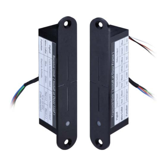
WLP-150 Wireless Power Transfer
Specifications
Transmitter on Frame Side
Input Power
Current Draw
Lock Status Output
Door Status Output
Receiver on Door Side
Output Power
Current Draw
Lock Status Input
Infrared Sensing
Door Opening Time
Maximum Door Gap
Maximum Tolerance
with 3/16" (4~5mm)
Door Gap
Operating Temperature
Humidity
Installation Instruction
13.8 VDC
1.1A/13.8VDC
*Requires 1.5 A power when energized
Relay (Dry contacts: N.O./N.C./Com.)
Rating: 3A/ 30VDC
Reed Switch
(Dry contacts: N.O./N.C./Com.)
Rating: 0.1A/ 20VDC
12 VDC
600mA/12VDC
Dry contacts: N.O./Com.
Transmitter
Receiver
15 / 30 seconds
*For fail-secure locks only
3/16" (4~5mm)
Horizontal alignment : 1/16" (1mm)
Vertical alignment : 1/16" (1mm)
IR Sensing: 1/16" (1mm)
32° to +120.2°F ( 0° to +49°C )
0 to 85% Non-condensing
Copyright © All Rights Reserved. P-MU-WLP-150 Published: 2021.03.10
IR Transmitter
Unit: mm
Inductive Coupling
Power Transfer
Receiver
Transmitter
Unit
Unit
1
Advertisement

Summary of Contents for GEM WLP-150
- Page 1 Horizontal alignment : 1/16" (1mm) Maximum Tolerance Vertical alignment : 1/16" (1mm) with 3/16" (4~5mm) IR Sensing: 1/16” (1mm) Door Gap 32° to +120.2°F ( 0° to +49°C ) Operating Temperature 0 to 85% Non-condensing Humidity Copyright © All Rights Reserved. P-MU-WLP-150 Published: 2021.03.10...
-
Page 2: Installation And Wiring
1. Door & Frame Inspection After checking the door and frame conditions, apply the templates at the appropriate location. The WLP-150 can be installed on the latch side, hinge side, or top of the door. 1a. Apply the door side template. - Page 3 2c. Check if the WLP-150 fits well in the cutout and 2d. Install mounting tabs using M5 screws. use the file if necessary. 3. Wood Door Installation 3a. Drill two 1" (25mm) diameter holes, 3b. Drill and cut the WLP-150 main body to a 1/8"...
- Page 4 N.C. Relay Output Green COM. (Lock Status) Blue N.O. Blue N.O. Lock Status Receiver Input Unit Green COM. 12VDC Door Leaf (Receiver) Red (+) OUTPUT Lock Power 12 VDC Output Black (-) Copyright © All Rights Reserved. P-MU-WLP-150 Published: 2021.03.10...
- Page 5 Power Output Lock Status Output RED(+) 12V (+) Electric Lock YEL (N/C) BLK (-) 12V (-) GRN (COM) max 12VDC GRN (COM) BLU (N/O) @600mA BLU (N/O) Lock Status Input OUTPUT INPUT Copyright © All Rights Reserved. P-MU-WLP-150 Published: 2021.03.10...
- Page 6 No door status Check installation position/alignment is correct output No sensor output Check installation position/alignment is correct (Both) No lock status Make sure lock status wires are connected to wireless power source output Copyright © All Rights Reserved. P-MU-WLP-150 Published: 2021.03.10...