Table of Contents
Advertisement
Quick Links
Intel® Server System
M70KLP Family
Service Guide
A guide providing instructions for the installation and
removal of serviceable system components, configuration options,
and available Intel accessories
Rev 1.0
March 2021
Delivering Breakthrough Datacenter System Innovation – Experience What's Inside!
Advertisement
Table of Contents

Related Manuals for Intel M70KLP Series


Summary of Contents for Intel M70KLP Series
- Page 1 Intel® Server System M70KLP Family Service Guide A guide providing instructions for the installation and removal of serviceable system components, configuration options, and available Intel accessories Rev 1.0 March 2021 Delivering Breakthrough Datacenter System Innovation – Experience What’s Inside!
- Page 2 Intel® Server System M70KLP Family Service Guide <Blank page>...
- Page 3 Intel® Server System M70KLP Family Service Guide Document Revision History Date Revision Changes March 2021 Production Release...
- Page 4 You may not use or facilitate the use of this document in connection with any infringement or other legal analysis concerning Intel products described herein. You agree to grant Intel a non-exclusive, royalty-free license to any patent claim thereafter drafted which includes subject matter disclosed herein.
- Page 5 Intel recommends the following steps be taken when performing any procedures described within this document or while performing service to any computer system.
- Page 6 Weight of the system: • Due to the weight of a system, Intel recommends carrying the system with two people supporting the system from the sides or using a mechanical lift or a cart when moving the system from one location to another.
-
Page 7: Table Of Contents
M.2 Storage Device Installation / Removal ......................47 3.6.1 M.2 SSD Installation ..............................47 3.6.2 M.2 SSD Removal ................................48 Intel® RAID Maintenance Free Backup Unit (RMFBU) Installation / Removal ........48 3.7.1 RMFBU Installation ................................ 49 3.7.2 RMFBU Removal ................................50 4. - Page 8 Intel® Server System M70KLP Family Service Guide 5.6.1 Intel® VROC 7.5 (VMD NVMe* RAID) Key Removal ................... 68 5.6.2 Intel® VROC 7.5 (VMD NVMe* RAID) Key Installation ..................69 Backplane Replacement .............................. 70 5.7.1 Backplane Removal ............................... 70 5.7.2 Backplane Installation ..............................71 Power Distribution Board (PDB) Replacement....................
- Page 9 Intel® Server System M70KLP Family Service Guide List of Figures Figure 1. Intel® Server System M70KLP (Standard System Option) ..................11 Figure 2. System Top Cover Removal ............................... 14 Figure 3. Chassis Intrusion Switch Cable Connection on Server Board ................14 Figure 4.
- Page 10 Figure 57. M.2 SSD Installation ................................47 Figure 58. M.2 SSD Removal ................................48 Figure 59. Intel® RMFBU Placement ..............................48 Figure 60. Intel® RMFBU Accessory Kit ............................. 49 Figure 61. Intel® RMFBU Placement ..............................49 Figure 62. Intel® RMFBU Removal ..............................50 Figure 63.
- Page 11 Figure 86. 2.5" SSD Installation to Drive Carrier .......................... 67 Figure 87. Drive Assembly Installation to Front Drive Bay ...................... 68 Figure 88. Intel® VROC Key Removal ..............................68 Figure 89. Intel® VROC Key Installation ............................69 Figure 90. Backplane Removal ................................70 Figure 91.
- Page 12 Intel® Server System M70KLP Family Service Guide List of Tables Table 1. Product Reference Documentation and Support Collaterals ................11 Table 2. System Features Table ................................51 Table 3. Front Panel Button and LED Operation ......................... 54 Table 4. DDR4 DIMM Attributes Table for “Identical” and “Like” DIMMs ................87...
-
Page 13: Introduction
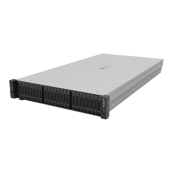
The Intel® Server System M70KLP is a purpose-built system that delivers power and performance at a peak efficiency in a 2U rack mount server form factor. It features the 3rd Gen Intel® Xeon® Scalable processor family in a four-socket configuration, delivering high core count and new hardware-enhanced security features. -
Page 14: About This Document
Intel® RAID Web Console 2 Utility – Various OS support** Public Controllers ** Go to following Intel website to download the latest system software updates, utility software, and drivers for onboard devices: http://downloadcenter.intel.com/ To download the latest product documentation, go to https://www.intel.com/content/www/us/en/support/products/77593/server-products/server-systems.html... -
Page 15: System Access And Cable Routing
Intel® Server System M70KLP Family Service Guide System Access and Cable Routing Most procedures documented in the following chapters will require access to the inside of the system. This chapter provides step-by-step instructions for the removal and reinstallation of both the system top cover and the system air duct. -
Page 16: Air Duct Removal
Intel® Server System M70KLP Family Service Guide Figure 2. System Top Cover Removal 1. Using a phillips screw driver, rotate the latch lock ¼ turn to the “Unlock” position (see Letter A). 2. Lift the latch to its full open position. The top cover will slide back (see Letter B). -
Page 17: Figure 4. Air Duct Lock Bar Removal
Intel® Server System M70KLP Family Service Guide Figure 4. Air Duct Lock Bar Removal 2. Using both hands, squeeze and hold the lock bar latches (see Letter A). 3. Lift the lock bar up and away from the chassis (see Letter B). -
Page 18: System Air Duct And Top Cover - Installation
Intel® Server System M70KLP Family Service Guide Figure 6. Air Duct Removal 5. Carefully lift the air duct up and away from the chassis (see Figure System Air Duct and Top Cover – Installation 2.2.1 Air Duct Installation Ensure that no cables interfere with placement of the air duct. Use the cable management brackets on each... -
Page 19: Figure 8. Air Duct Placement
Intel® Server System M70KLP Family Service Guide Figure 8. Air Duct Placement 1. Position the air duct over all alignment features. • Hold the air duct over the chassis and match alignment pins found on each cable management bracket to matching alignment holes on the air duct. -
Page 20: Figure 10. Air Duct Lock Bar Orientation
Intel® Server System M70KLP Family Service Guide 3. (If present) Connect the M.2 SSD interface board cable to the slim-line connector on the server board below the back edge of the air duct (see Figure 4. Locate the air duct lock bar. -
Page 21: System Top Cover Installation
Intel® Server System M70KLP Family Service Guide Figure 12. Chassis Intrusion Switch Cable to Server Board 9. Orient the latch of chassis intrusion cable connector to the cut-out keyed side of the 4-pin connector on the server board (see above figure). -
Page 22: Figure 14. Top Cover Placement
Intel® Server System M70KLP Family Service Guide Figure 14. Top Cover Placement 2. Align and lower the top cover onto the chassis and slide forward until is stops (see Letter A). Note: the top cover will not be fully engaged with the chassis in this step. -
Page 23: Cable Routing
Intel® Server System M70KLP Family Service Guide Cable Routing Proper cable routing and management within the system is necessary to correctly install the system air duct. In addition, managing how cables are routed within the system is critically important for proper airflow and maintaining system thermals. -
Page 24: Cable Management Brackets
Intel® Server System M70KLP Family Service Guide 2.3.1 Cable Management Brackets Mounted to each chassis sidewall are two cable management brackets as shown in the following figure. Open bracket to install cables Close bracket to secure cables Cables routed and secured Figure 17. -
Page 25: Figure 19. System Fan Housing Removal
Intel® Server System M70KLP Family Service Guide Figure 19. System Fan Housing Removal 3. Lift the latches on both ends of the fan housing to their full upright position (see Letter A). 4. Grasp the fan housing on both ends and pull it straight up from the chassis (see Letter B). -
Page 26: Figure 21. Fan Housing Mounting Bracket Installation
Intel® Server System M70KLP Family Service Guide 2.3.2.2 Fan Housing Installation 1. (If removed) Reinstall one or both fan housing mounting bracket(s) to the chassis sidewall. Note: Each mounting bracket is stamped (L) or (R) to identify which side of the chassis the bracket mounts to. -
Page 27: Figure 23. System Fan Housing Placement
Intel® Server System M70KLP Family Service Guide 2. Lift the latches on both ends of the empty fan housing. Figure 23. System Fan Housing Placement 3. Align the slots on both ends of the fan housing to the alignment pins of the mounting brackets on the chassis sidewalls (see Letter A). -
Page 28: Figure 25. System Fan Placement Orientation Features
Intel® Server System M70KLP Family Service Guide 5. Close both fan housing latches at the same time. The housing will position and secure itself to the chassis (see Letter B). Airflow indicator Airflow Fan Interface Connector to Server board Figure 25. System Fan Placement Orientation Features... -
Page 29: System Options And Accessories
Intel® Server System M70KLP Family Service Guide System Options and Accessories This chapter provides instructions for the integration of system options and other available Intel accessories. Chapter 5, “FRU Replacement” for complete replacement instructions for components identified as field replaceable. -
Page 30: Rail Kit Installation
Intel® Server System M70KLP Family Service Guide Rail Kit Installation The Intel® Server System M70KLP includes a rail kit for system installation into a 4-post rack or cabinet. The following installation guidelines should be observed. • For proper system ventilation, leave a minimum of 15 cm clearance in the front and rear of the system. -
Page 31: Figure 29. Rail Kit - Re-Position Middle Rail
Intel® Server System M70KLP Family Service Guide Figure 29. Rail Kit – Re-position Middle Rail 2. Rotate the tab (a) and slide the middle rail back into the outer rail. Figure 30. Rail Kit - Inner Rail Attachment to Chassis 3. -
Page 32: Figure 31. Rail Kit - Rail Installation To Mounting Posts
Intel® Server System M70KLP Family Service Guide Figure 31. Rail Kit - Rail Installation to Mounting Posts 4. Install the rails one at a time to the back and front posts of the rack or cabinet. • Position the Rear Bracket along the outside of the rear post and push pins into the post from the back (see “Rear Bracket”... -
Page 33: Figure 32. Rail Kit - Server Installation Into Rails
Intel® Server System M70KLP Family Service Guide Caution: The server system is very heavy. It is highly recommended that two or more people and/or the aid of a mechanical lift be used to install the server into the rack or cabinet. -
Page 34: Add-In Card Installation And Removal
Intel® Server System M70KLP Family Service Guide Add-in Card Installation and Removal PCIe* add-in cards can be installed to any available PCIe add-in cards slots found on the server board and/or to installed riser cards (if present). No tools are required to install or remove a PCIe add-in card. -
Page 35: Pcie* Add-In Card Removal - Server Board Add-In Slots
Intel® Server System M70KLP Family Service Guide 3.2.2 PCIe* Add-in Card Removal - Server Board Add-in slots Required Tools and Supplies • Anti-static wrist strap and conductive workbench pad (recommended) System Prerequisites • The system must be powered off and AC Power cord(s) disconnected •... -
Page 36: Pcie* Add-In Card Installation - Riser Cards
Intel® Server System M70KLP Family Service Guide 3.2.3 PCIe* Add-in Card Installation – Riser Cards The following illustrations show the Riser 1 assembly. However, the instructions to add or remove an add-in card is the same regardless of riser card assembly location. -
Page 37: Figure 36. Riser Card Assembly Removal
Intel® Server System M70KLP Family Service Guide Figure 36. Riser Card Assembly Removal 3. Lift the riser assembly from the system (see Letter C). Figure 37. Riser Card - Filler Plate Removal 4. Press the blue latch to open the black filler plate retention cover (see Letters A and B). -
Page 38: Figure 38. Riser Card - Add-In Card Installation
Intel® Server System M70KLP Family Service Guide Figure 38. Riser Card - Add-in Card Installation 6. Carefully insert the edge connector of the add-in card into the slot on the riser card. Ensure the card is fully seated. Figure 39. Riser Card - Close Filler Plate Retention Cover 7. -
Page 39: Pcie* Add-In Card Removal - Riser Card
Intel® Server System M70KLP Family Service Guide Figure 41. Riser Card Installation into System 9. Align the back of the riser assembly to the slot guides on the chassis back panel (see Letter A). 10. Carefully lower the riser assembly into the chassis, ensuring the edge connector of the riser card aligns with the riser slot on the server board. -
Page 40: Figure 42. Riser Card Assembly Removal
Intel® Server System M70KLP Family Service Guide 1. Fold up the blue tab located at the end of the riser card assembly (see Letter A). 2. Rotate the blue tab counterclockwise ¼ turn to release the riser assembly from the server board (see Letter B). -
Page 41: Figure 43. Add-In Card Removal From Riser Assembly
Intel® Server System M70KLP Family Service Guide Figure 43. Add-in Card Removal from Riser Assembly 1. Press the blue latch to open the black filler plate retention cover (see Letters A and B). 2. Remove the add-in card from riser assembly (see Letter C). -
Page 42: Figure 44. Riser Card - Auxiliary Pcie* Cable Connection
Intel® Server System M70KLP Family Service Guide Figure 44. Riser Card - Auxiliary PCIe* Cable Connection 5. (If present) Reattach all auxiliary PCIe cables to the backside of the riser card. Cables should be locked when fully seated. Figure 45. Riser Card Installation into System 6. -
Page 43: Front 2.5" Drive Installation
Intel® Server System M70KLP Family Service Guide Front 2.5” Drive Installation The front drive bay may have support for 8, 16, or 24 drive bays. Each drive bay will include a drive carrier that must be populated with a 2.5” drive (SSD or HDD) or supplied drive blank. All drives attached to a common backplane must match media type (SSD or HDD). -
Page 44: Figure 48. 2.5" Drive Installation To Drive Carrier
Intel® Server System M70KLP Family Service Guide Figure 48. 2.5” Drive Installation to Drive Carrier 3. Carefully position the drive between the carrier side rails (see Letter A). 4. Ensure all mounting holes on the rails align with those of the drive. -
Page 45: Ddr4 Dimm / Intel® Optane™ Pmem Installation
Intel® Server System M70KLP Family Service Guide DDR4 DIMM / Intel® Optane™ PMem Installation This section describes adding a standard DDR4 DIMM or Intel® Optane™ PMem device to an existing memory configuration. For replacement instructions, see Section 5.2. DDR4 DIMM and Intel® Optane™ PMem will be commonly referred to as “Memory Module” in the following instructions. -
Page 46: Network Adapter For Ocp* 3.0 (Small Form Factor) - Installation / Removal
(see Letter D). 6. Ensure that the ejection tabs are firmly in place (see Letter E). Note: Intel® Optane™ PMem devices require additional steps to enable and configure them. Refer to the appropriate Intel® Optane™ PMem documentation to complete the installation process. -
Page 47: Network Adapter For Ocp* 3.0 (Small Form Factor) Installation
Intel® Server System M70KLP Family Service Guide 3.5.1 Network Adapter for OCP* 3.0 (Small Form Factor) Installation Figure 52. OCP* Card Bay Insert Removal 1. Remove the OCP card bay insert: • Loosen the thumb screw on the right side of the insert (see Letter A). -
Page 48: Network Adapter For Ocp* 3.0 (Small Form Factor) Removal
Intel® Server System M70KLP Family Service Guide 3.5.2 Network Adapter for OCP* 3.0 (Small Form Factor) Removal Figure 54. OCP* Card with Pull-tab Removal 1. Loosen the thumbscrew (see Letter A). 2. Using the pull-tab, pull the OCP card from the chassis (see Letter B). -
Page 49: M.2 Storage Device Installation / Removal
Intel® Server System M70KLP Family Service Guide M.2 Storage Device Installation / Removal On the system air duct is an M.2 SSD interface board that supports up to two SATA M.2 SSDs. Each connector can support SSDs that conform to a 22110 (110 mm) or 2280 (80 mm) form factor. -
Page 50: M.2 Ssd Removal
Depending on the system configuration, the Intel® Server System M70KLP supports up to three Intel® RMFBU accessories (Standard System) or one Intel® RMFBU (GPU supported system). In either system configuration, the Intel® RMFBU is mounted to the top side of the system air duct as shown in Figure To support three RMFBUs in a standard system, two RMFBUs are stacked on top of each other with the third mounted next to them. -
Page 51: Rmfbu Installation
Intel® Server System M70KLP Family Service Guide Intel® RAID Maintenance Free Backup Unit (RMFBU) accessory kits include several components, including a molded plastic mounting bracket. In this system, the mounting bracket is not used. Figure 60. Intel® RMFBU Accessory Kit Required Tools and Supplies •... -
Page 52: Rmfbu Removal
Intel® Server System M70KLP Family Service Guide Open the pre-installed hook and loop strap on top of the air duct. Position the RMFBU within the designated mounting location on the air duct (see Letter A). Using the hook and loop strap, securely fasten down the RMFBU. -
Page 53: System Features Overview
Maximum supported processor TDP: ≤ 250W ** Supported 3 Gen Intel® Xeon® Scalable processor SKUs must end in (H) or (HL). All other processor SKUs are not supported. ** Previous generation Intel® Xeon® processor and Intel® Xeon® Scalable processor families are... - Page 54 (DPC – DIMMs per Channel) • Gold 63xx: 2933 (1 or 2 DPC) Intel® Optane™ persistent memory 200 Series (App Direct Mode Only) Memory Speeds in MT/s : 2666 (Intel® Optane™ PMem + DDR4 SDRAM configurations) • Up to four (4) onboard •...
-
Page 55: Figure 64. 8 X2.5" Ssd Front Drive Bay Configuration
TPM 2.0 Option (Rest of the world) - iPC KLPTPM Note: China only TPM not supported Security Intel® Platform Firmware Resilience (Intel® PFR) Converged Boot Guard and Intel® Trusted Execution (Intel® TXT) Rack mount rails Rack Mount Kit Tool-less attachment to chassis and rack installation... -
Page 56: Figure 67. Front Control And I/O Panels
Intel® Server System M70KLP Family Service Guide Integrated within the front system handles are a control panel (Left) and I/O panel (Right), as shown below. Memory Status Fan Status System Status LED Power Button / LED VGA Connector USB 3.0 Port System ID Button / USB 2.0 Port... -
Page 57: Figure 68. 2.5" Hot Swap Drive Led Identification
Riser #0 and up to three (3) half-height/half-length PCIe add-in cards from Riser #1. The top side of the air duct has mounting features for an M.2 interface board capable of supporting up to two (2) SATA M.2 SSDs, and support for up to three (3) Intel® RAID Maintenance Free Backup (RMFBU) modules. -
Page 58: Figure 70. Standard System - Back Panel Features
The top side of the air duct has mounting features for an M.2 interface board capable of supporting up to two (2) SATA M.2 SSDs, and support for one (1) Intel® RAID Maintenance Free Backup (RMFBU) module. -
Page 59: Figure 72. 2000W Power Supply Module
Figure 72. 2000W Power Supply Module Important Note: All integrated L9 system configurations from Intel will draw greater than 1000W of power when running medium to heavy workloads. To support this power requirement, systems must be connected to a 220V AC input power source to operate. A system running a medium to heavy workload and is... -
Page 60: Figure 73. Server Board Features
Intel® Server System M70KLP Family Service Guide Integrated within the server system is the Intel® M70KLP server board. The following illustration identifies the supported features and available system option interconnects. Figure 73. Server Board Features... -
Page 61: Fru Replacement
Or for component replacement that does not require top cover removal, the time the component is removed from the system to the time it is reinstalled. Intel recommends that all system service procedures be performed by a qualified service technician. Before You Begin Before replacement of any system components, review all the safety and ESD precautions found in the Safety Warnings section at the beginning of this document. -
Page 62: System Fan Replacement
Intel® Server System M70KLP Family Service Guide System Fan Replacement Required Tools and Supplies • Anti-static wrist strap and other anti-ESD precautions (recommended) • No tools are required to replace a faulty system fan • Replacement system fan Average Time to Complete: < 3 minutes Procedure Prerequisites •... -
Page 63: Figure 75. System Fan
Intel® Server System M70KLP Family Service Guide Locate and unpack the replacement fan. Airflow indicator Airflow Fan Interface Connector to Server board Figure 75. System Fan Orient the fan so the arrow on top of the fan points to the back of the system. -
Page 64: Dimm / Intel® Optane™ Pmem Replacement
Sections 2.1.1 and 2.1.2. Instructions to physically replace a DDR4 DIMM or an Intel® Optane™ PMem 200 series module are the same. For the following procedure, Standard DDR4 DIMMs and Intel® Optane™ PMem devices are commonly referred to as “Memory Module”... -
Page 65: System Battery Replacement
10. Reinstall the system air duct and top cover (see Sections 2.2.1 and 2.2.2). Note: Replacing Intel® Optane™ PMem devices requires additional steps to enable and configure them. Refer to the appropriate Intel® Optane™ PMem documentation to complete the installation process for these devices. -
Page 66: Power Supply Module Replacement
Intel® Server System M70KLP Family Service Guide Unpack the new battery Figure 80. System Battery Installation Orient the battery so that its positive (+) side is facing up. Carefully insert the new battery into the battery socket. Ensure it is locked in place. -
Page 67: Front 2.5" Drive Replacement
Intel® Server System M70KLP Family Service Guide 1. Identify the power supply module to be replaced (see the LED on the back of the power supply). 2. Disconnect the AC power cord of the faulty power supply from the AC power source. -
Page 68: Drive Removal
Intel® Server System M70KLP Family Service Guide 5.5.1 Drive Removal Figure 83. Front Drive Bay - Drive Extraction 1. Remove the drive carrier from the system. • Push the button to release the drive carrier latch (see Letter A). •... -
Page 69: Drive Replacement
Intel® Server System M70KLP Family Service Guide Lock Lock Tabs Drive Carrier Lock Pin Holes Lock Figure 85. Drive Blank Installation to Drive Carrier • Locate the drive blank insert. • Position the drive blank insert behind the drive carrier. -
Page 70: Intel® Vroc 7.5 Key Replacement
Intel® VROC 7.5 (VMD NVMe* RAID) Key Removal Figure 88. Intel® VROC Key Removal Locate the Intel® VROC for NVMe Key near the bottom right edge of the server board. Using the key pull tab, carefully pull up on the key until it disengages from the connector. -
Page 71: Intel® Vroc 7.5 (Vmd Nvme* Raid) Key Installation
Intel® VROC 7.5 (VMD NVMe* RAID) Key Installation Figure 89. Intel® VROC Key Installation Remove the Intel® VROC for NVMe key from its packaging. Ensure the key and server board connector are oriented correctly. Press the key down onto the connector until it locks into place. -
Page 72: Backplane Replacement
Intel® Server System M70KLP Family Service Guide Backplane Replacement The following provides instructions for the replacement of a faulty backplane. Required Tools and Supplies • No tools are required to replace a faulty backplane • Follow all ESD precautions described in the Safety section at the beginning of this document •... -
Page 73: Backplane Installation
Intel® Server System M70KLP Family Service Guide 5.7.2 Backplane Installation 1. Locate and unpack the replacement backplane. Figure 91. Backplane Installation 2. Carefully align and place the two mounting keyholes of the backplane over the mounting studs on the drive bay (see Letter A). -
Page 74: Power Distribution Board (Pdb) Replacement
Intel® Server System M70KLP Family Service Guide Power Distribution Board (PDB) Replacement The following provides instructions for the replacement of a faulty power distribution board (PDB). Required Tools and Supplies • Anti-static wrist strap, an ESD safe workbench, and other anti-ESD precautions (recommended) •... -
Page 75: Power Distribution Board (Pdb) Installation
• Remove the system top cover and air duct (see Sections 2.1.1 and 2.1.2). Caution: Fin edges of the processor heat sink are very sharp. Intel recommends wearing thin ESD protective gloves when handling the PHM during the following procedures. -
Page 76: Processor Heat Sink Module (Phm) Removal
Intel® Server System M70KLP Family Service Guide Caution: Processor heat sinks are easily damaged if handled improperly. See the following image for proper handling. Figure 94. Processor Heat Sink Handling 5.9.1 Processor Heat Sink Module (PHM) Removal 1. Identify and locate the faulty processor. -
Page 77: Phm Disassembly
Intel® Server System M70KLP Family Service Guide If not replacing the processor, install the original plastic socket cover over the processor socket. Figure 96. Processor Socket Cover Installation • Squeeze the finger grips at each end of the cover (see Letter A). -
Page 78: Phm Reassembly
Intel® Server System M70KLP Family Service Guide Figure 98. Processor Carrier Clip Removal from PHM Assembly 3. Return the lever to the original position (see Letter C). 4. Detach the processor carrier clip from the heat sink. • Unlatch the hook on each corner of the processor carrier clip and lift it from the heat sink (see Letter D). -
Page 79: Figure 100. Installing Processor Carrier Clip Onto Processor - Part 2
Intel® Server System M70KLP Family Service Guide Figure 100. Installing Processor Carrier Clip onto Processor – Part 2 1. With the processor still in its tray, place the processor carrier clip over the processor. 2. Ensure the pin 1 indicator on the processor carrier clip is aligned with the pin 1 indicator of the processor. -
Page 80: Figure 102. Processor Heat Sink Anti-Tilt Wires In The Outward Position
Intel® Server System M70KLP Family Service Guide Figure 102. Processor Heat Sink Anti-tilt Wires in the Outward Position 7. Set the anti-tilt wire over each of the four heat sink fasteners to their outward position. Figure 103. Pin 1 Indicator of Processor Carrier Clip 8. -
Page 81: Phm Installation
Intel® Server System M70KLP Family Service Guide 5.9.4 PHM Installation If installed, remove the plastic cover from the processor socket Caution: Do not touch the socket pins. The pins inside the processor socket are extremely sensitive. A damaged processor socket may produce unpredictable system errors. -
Page 82: Figure 106. Phm Installation Onto Server Board
Intel® Server System M70KLP Family Service Guide Figure 106. PHM Installation onto Server Board 1. Set all four anti-tilt wires on the heat sink to the inward position (see Letter A). 2. Align the pin 1 indicators of the processor carrier clip and processor with the pin 1 indicator on the socket assembly bolster plate. -
Page 83: 5.10 Server Board Replacement
Intel® Server System M70KLP Family Service Guide 5.10 Server Board Replacement Replacing the server board within the Intel® Server System M70KLP is considered a major service procedure. This procedure should only be performed by qualified service technicians. Before You Begin Before performing this procedure, review all the safety and ESD precautions found in the Safety Warnings section at the beginning of this document. -
Page 84: Server Board Removal
Intel® Server System M70KLP Family Service Guide 11. Remove the Power Distribution Board (PDB) mounted to the front of the power supply bay (see Section 5.8.1). 12. Label and disconnect all remaining cables attached to the server board. Note: All cable connectors have latches to secure them to the connectors on the board. DO NOT attempt to pull off a cable without unlatching them. -
Page 85: Server Board Installation
Intel® Server System M70KLP Family Service Guide 5.10.3 Server Board Installation This section is a continuation from Section 5.10.2. 1. Locate and unpack the replacement server board. • The replacement server board is pre-assembled to the mounting plate • Take care to only handle the server board by its edges. -
Page 86: System Reassembly
3. Reset BIOS options to desired settings. Note: If Intel® Optane™ PMem devices we re-installed, it may be necessary to unlock them for continued use and to retrieve any persistent data they may still have written on them. See the Intel® Optane™ PMem... -
Page 87: Appendix A. Getting Help
Server and chassis accessory parts list for ordering upgrades or spare parts • A searchable knowledge base to search for product information throughout the support site If a solution cannot be found at Intel’s support site, send an email to Intel’s technical support center using the online form available at http://www.intel.com/p/en_US/support/contactsupport. -
Page 88: Appendix B. Memory Population Rules
Appendix B. Memory Population Rules The Intel® Server System M70KLP supports up to 48 DDR4 DIMMs; 12 DIMM slots per processor. Each processor supports six memory channels identified as 0 – 5. Each memory channel supports two DIMM slots identified as Slot 0 (White slots) and Slot 1 (Black slots). -
Page 89: Table 4. Ddr4 Dimm Attributes Table For "Identical" And "Like" Dimms
However, Intel may ship back a validated “Like” DIMM. A “Like” DIMM may be from the same vendor but may not be the same revision # or model #, or it may be an Intel validated DIMM from a different vendor. At a minimum, all “Like”... - Page 90 The following DDR4 SDRAM population rules apply for most reliable operation. • Mixed DDR4 DIMM rules: Note: Intel will only support mixed DDR4 DRAM DIMM configurations as defined in the Intel DDR4 Support Disclaimer above. o Mixing DDR4 DIMMs of different speeds and latencies is not supported within or across processors.
- Page 91 • A minimum of one PMem module per system. • When populating DDR4 DRAM + PMem, Intel recommends devices have a DDR4 DIMM capacity to PMem module capacity ratio of 1:1, 1:2, or 1:4 Examples: o 1:1 = 128 GB DRAM DIMM : 128 GB PMem Module...
-
Page 92: Appendix C. Product Safety - Multi-Language
Intel® Server System M70KLP Family Service Guide Appendix C. Product Safety – Multi-Language WARNING: English (US) The power supply in this product contains no user-serviceable parts. There may be more than one supply in this product. Refer servicing only to qualified personnel. - Page 93 Intel® Server System M70KLP Family Service Guide For proper cooling and airflow, always reinstall the chassis covers before turning on the system. Operating the system without the covers in place can damage system parts. To install the covers: 1. Check first to make sure you have not left loose tools or parts inside the system.
- Page 94 Intel® Server System M70KLP Family Service Guide ОСТОРОЖНО: русский Блок питания данного изделия не содержит деталей, подлежащих обслуживанию пользователем. В этом изделии может быть несколько блоков питания. Обслуживание должно выполняться только квалифицированным персоналом. Не модифицируйте и не используйте прилагаемый кабель питания, если он не...
- Page 95 Intel® Server System M70KLP Family Service Guide ОСТОРОЖНО: русский (продолжение) Для обеспечения надлежащего охлаждения и воздушного потока всегда устанавливайте на место крышки корпуса перед включением системы. Работа системы без установленных крышек может привести к повреждению компонентов системы. Чтобы установить крышки, выполните следующие действия: Сначала...
- Page 96 Intel® Server System M70KLP Family Service Guide УВАГА! Українська Джерело живлення в цьому виробі не містить жодних частин, які користувачі могли б обслуговувати самостійно. Цей виріб може містити більше одного джерела живлення. Обслуговувати його може виключно кваліфікований персонал. Не намагайтеся модифікувати шнур живлення змінного струму з комплекту або користуватися...
- Page 97 Intel® Server System M70KLP Family Service Guide УВАГА! Українська (продовження) Для правильного охолодження та вентиляції завжди повертайте на місце кришки корпусу перед увімкненням системи. Робота системи без кришок може пошкодити деталі системи. Щоб установити кришки, виконайте такі дії: Спочатку переконайтеся, що всередині системи не залишилося деталей або незакріплених...
- Page 98 Intel® Server System M70KLP Family Service Guide AVERTISSEMENT: Français Le bloc d'alimentation de ce produit ne contient aucune pièce pouvant être réparée par l'utilisateur. Ce produit peut contenir plus d'un bloc d'alimentation. Veuillez contacter un technicien qualifié en cas de problème.
- Page 99 Intel® Server System M70KLP Family Service Guide Afin de permettre le refroidissement et l’aération du système, réinstallez toujours les panneaux du boîtier avant de mettre le système sous tension. Le fonctionnement du système en l’absence des panneaux risque d’endommager ses pièces. Pour installer les panneaux, procédez comme suit:...
- Page 100 Intel® Server System M70KLP Family Service Guide WARNUNG: Deutsch Benutzer können am Netzgerät dieses Produkts keine Reparaturen vornehmen. Das Produkt enthält möglicherweise mehrere Netzgeräte. Wartungsarbeiten müssen von qualifizierten Technikern ausgeführt werden. Versuchen Sie nicht, das mitgelieferte Netzkabel zu ändern oder zu verwenden, wenn es sich nicht genau um den erforderlichen Typ handelt.
- Page 101 Intel® Server System M70KLP Family Service Guide Zur ordnungsgemäßen Kühlung und Lüftung muß die Gehäuseabdeckung immer wieder vor dem Einschalten installiert werden. Ein Betrieb des Systems ohne angebrachte Abdeckung kann Ihrem System oder Teile darin beschädigen. Um die Abdeckung wieder anzubringen: 1.
- Page 102 Intel® Server System M70KLP Family Service Guide AVVERTENZA: Italiano Rivolgersi ad un tecnico specializzato per la riparazione dei componenti dell'alimentazione di questo prodotto. È possibile che il prodotto disponga di più fonti di alimentazione. Non modificare o utilizzare il cavo di alimentazione in c.a. fornito dal produttore, se non corrisponde esattamente al tipo richiesto.
- Page 103 Intel® Server System M70KLP Family Service Guide Per il giusto flusso dell’aria e raffreddamento del sistema, rimettere sempre le coperture del telaio prima di riaccendere il sistema. Operare il sistema senza le coperture al loro proprio posto potrebbe danneggiare i componenti del sistema. Per rimettere le coperture del telaio: 1.
- Page 104 Intel® Server System M70KLP Family Service Guide ADVERTENCIAS: Español El usuario debe abstenerse de manipular los componentes de la fuente de alimentación de este producto, cuya reparación debe dejarse exclusivamente en manos de personal técnico especializado. Puede que este producto disponga de más de una fuente de alimentación.
- Page 105 Intel® Server System M70KLP Family Service Guide Para obtener un enfriamiento y un flujo de aire adecuados, reinstale siempre las tapas del chasis antes de poner en marcha el sistema. Si pone en funcionamiento el sistema sin las tapas bien colocadas puede dañar los componentes del sistema. Para instalar las tapas: 1.
- Page 106 Intel® Server System M70KLP Family Service Guide אזהרה: עברית ממקור אספקת חשמל אספקת החשמל במוצר זה לא מכילה חלקים שניתנים לשירות על ידי משתמש. ייתכן שיש יותר .אחד במוצר זה. לקבלת שירות יש לפנות רק אל אנשים המוסמכים לכך הנדרש. למוצר עם יותר ממקור...
- Page 107 Intel® Server System M70KLP Family Service Guide תקין מחדש את מכסי המעטפת לפני הפעלת המערכת. הפעלת המערכת ללא לקירור ולזרימת אוויר תקינים, יש תמיד לה :המכסים במקומם, עלולה לגרום נזק לחלקי המערכת. להתקנת המכסים .ו חלקים רופפים בתוך המערכת יש לבדוק תחילה כדי לוודא שלא נשארו כלים א...
-
Page 108: Appendix D. Glossary
Intel® Server System M70KLP Family Service Guide Appendix D. Glossary Definition Term ACPI Advanced Configuration and Power Interface Add-In Card ASHRAE American Society of Heating, Refrigerating and Air-Conditioning Engineers BIOS Boot Specification Baseboard Management Controller BIOS Basic Input/Output System CMOS... - Page 109 Intel® Server System M70KLP Family Service Guide Definition Term PMBus Power Management Bus Persistent Memory Module POST Power-on Self-Test Power Supply Unit Quad Rank RAID Redundant Array of Independent Disks Random Access Memory RDIMM Registered DIMM RMFBU RAID Maintenance Free Backup Unit...