
Related Manuals for Alesis Ineko


Summary of Contents for Alesis Ineko
- Page 1 TABLE-TOP STEREO EFFECTS PROCESSOR Reference Manual 2001 Ineko Reference Manual...
- Page 2 Ineko Manual Ineko Reference Manual...
-
Page 3: Table Of Contents
Connecting to the Channel Inserts of a mixing console:...22 Connecting to the Main Inserts of a mixing console: ...23 Connecting to the inserts on an instrument amplifier: ...23 About Audio Cables...24 Using the Ineko... 25 Description of Controls...25 List of Programs...25 Reverb Effects (1 Column) ...26... - Page 4 Cleaning...44 Refer All Servicing to Alesis ...44 Obtaining Repair Service...44 Specifications ...46 Audio I/O...46 Audio Performance...46 Physical ...45 Alesis Limited Warranty ... 47 Ineko Reference Manual...
- Page 5 Ineko Manual Ineko Reference Manual...
-
Page 6: Welcome
Welcome! Thank you for making the Alesis Ineko™ a part of your studio. Since 1984, we've been designing and building creative tools for the audio community. We believe in our products, because we've heard the results that creative people like you have achieved with them. -
Page 7: How To Use This Manual
Chapter 1: Quick Start. recording, this will get you started using the Ineko right away. It's a short guide to the essential elements of connections and operation. -
Page 8: Important Safety Instructions
9. Do not defeat the safety purpose of the polarized or grounding- type plug. A polarized plug has two blades with one wider than the other. A grounding-type plug has two blades and a third grounding prong. The wide blade or the third prong are Ineko Reference Manual... - Page 9 17. Do not expose the apparatus to dripping or splashing. Do not place objects filled with liquids (flower vases, softdrink cans, coffee cups) on the apparatus. 18. WARNING: To reduce the risk of fire or electric shock, do not expose this apparatus to rain or moisture. Ineko Reference Manual...
- Page 10 à la terre. Cette dernière est présente pour votre sécurité. Si le cordon secteur ne rentre pas dans la prise de courant, demandez à un électricien qualifié de remplacer la prise. Ineko Reference Manual...
- Page 11 Beim Benutzen dieses Produktes beachten Sie bitte die folgenden Sicherheitshinweise: (German) 1. Lesen Sie die Hinweise. Halten Sie sich an die Anleitung. Beachten Sie alle Warnungen. Beachten Sie alle Hinweise. Bringen Sie das Gerät nie mit Wasser in Berührung. Ineko Reference Manual...
- Page 12 Gehörschäden verursachen. Betreiben Sie es nicht über längere Zeit mit hoher Lautstärke oder einem Pegel, der Ihnen unangenehm is. Wenn Sie ein Nachlassen des Gehörs oder ein Klingeln in den Ohren feststellen, sollten Sie einen Ohrenarzt aufsuchen. Ineko Reference Manual...
-
Page 13: Ce Declaration Of Conformity
CE Declaration of Conformity See the Internet site: www.alesis.com Ineko Reference Manual... -
Page 14: Fcc Notice
TV reception. The user is cautioned that changes and modifications made to the equipment without the approval of manufacturer could void the user’s authority to operate this equipment. Ineko Reference Manual... -
Page 15: Quick Start Guide
Quick Start Guide If you can't wait to get started: The Alesis Ineko™ is a unique product, but its basic hookup and operation is similar to other effects processors in most respects. If you're experienced with signal processors, this chapter is a "shorthand"... -
Page 16: Step 2: Try Some Effects
If you aren’t hearing any effect, check your connections or try another program. Some programs are easier to hear than others. all the way down so that you don’t INPUT light comes on, then back INPUT buttons to change programs on Ineko Reference Manual knob... - Page 17 1 • quick start guide Ineko Reference Manual...
- Page 18 • chapter 1 Ineko Reference Manual...
-
Page 19: Connections
POWER INPUT AC power outlet. Tip: It’s good practice to not plug in the Ineko until all other audio cables are hooked up as well. Make sure your amplifier or powered speakers are switched off when turning the Ineko on or off to avoid damage. -
Page 20: Connecting Inputs And Outputs
Most mixing consoles have post-fader effects send and return jacks on their rear panels. This is usually the best choice for connecting the Ineko, as you will be able to use an effect on several sources at once. Ineko In... - Page 21 2 • connections direct and effect signal with the effects return level control on your mixer. Ineko Reference Manual...
-
Page 22: Connecting To The Channel Inserts Of A Mixing Console
Most mixing consoles have a jack near the mic and line inputs labeled "Insert". This is typically a TRS jack with the send and return on the same jack. To use the Ineko as a channel insert, you will need an insert cable (not included). -
Page 23: Connecting To The Main Inserts Of A Mixing Console
In addition to channel inserts, most mixing consoles have main insert jacks near the main outputs. You can use insert cables to connect the Ineko to the main L/R bus the same way you connect it to a pair of channels. Simply connect one insert cable... -
Page 24: About Audio Cables
About Audio Cables The connections between the Ineko and your studio are your music’s lifeline, so use only high quality cables. These should be low-capacitance shielded cables with a stranded (not solid) internal conductor and a low-resistance shield. Although quality cables cost more, they do make a difference. -
Page 25: Using The Ineko
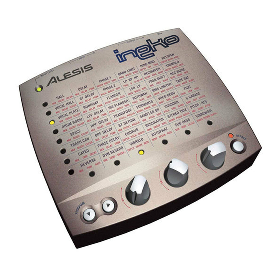
This section explains the functions of the controls on the Ineko and lists the programs and their parameters’ functions. Description of Controls The Ineko has five controls on its front panel: PROGRAM This button changes programs within a column of effects. -
Page 26: Reverb Effects (1 St Column)
Reverb Effects (1 Column) The first column of effects programs in the Ineko are all reverberation programs. Reverb is made up of a large number of distinct echoes, called reflections. In a natural acoustic space, each reflection’s amplitude and brightness decays over time. - Page 27 This reverb has a reversed decay envelope – fading in, then cutting off abruptly. Balance between direct/reverb signal. TIME Length of time until the effect cuts off. RATE This adjusts the fade-in slope, or “attack” of the effect. Turn the control clockwise for a more gradual fade-in. Ineko Reference Manual...
-
Page 28: Delay Effects (2 Nd Column)
Delay Effects (2 Column) The second column of effects programs in the Ineko are delay programs. Delay provides a discrete repetition, or echo of the input signal. A portion of the delayed signal is fed back into the input to produce additional echoes of the original signal. - Page 29 Balance between direct/reverb signal SENS This controls the sensitivity of the effect – how closely it follows the input level. -DECAY+ This adjusts whether the reverb decay time grows shorter or longer when the input level increases. Ineko Reference Manual...
-
Page 30: Pitch Effects (3 Rd Column)
Classic sweeping tape flange effect. PITCH Adjusts the center frequency from which the LFO modulates up and down. This effectively sets the frequency range and character of the effect. WIDTH Controls how far the LFO sweeps. RATE Rate of the LFO. Ineko Reference Manual... - Page 31 Balance of direct and effected signals. PITCH Adjusts the center frequency from which the LFO modulates up and down. This effectively sets the frequency range and character of the effect. WIDTH Controls how far the LFO sweeps. Ineko Reference Manual...
- Page 32 VIBRATO LFO controlled pitch shift. DEPTH How far the pitch is shifted by the LFO. SHAPE Shape of the LFO wave. Constantly variable from a smooth sine to chaotic sample-and-hold. RATE Rate of the LFO. Ineko Reference Manual...
-
Page 33: Filter Effects (4 Th Column)
Filter Effects (4 Column) The fourth column of effects on the Ineko has a series of filter effects. These effects change the frequency response of the input by boosting or cutting parts of the signal. BAND LIMIT Limits the high and low frequency range of the input. Good for emulating telephones, radio and other low-fidelity sound sources. - Page 34 Rate at which the filter frequency will change. RESONATOR Resonant band-pass filters swept by an LFO. PITCH Center frequency of the filters. RANGE Controls how far from the center frequency the filters are swept. RATE Rate of the LFO. This determines how much Ineko Reference Manual...
- Page 35 Sensitivity of the envelope. closely the phasor follows the input level. FDBK Amount of feedback. Turn clockwise to make the effect more pronounced. RATE Rate of the envelope. This determines how quickly the phasor sweeps. Ineko Reference Manual This determines how...
-
Page 36: Misc. Effects (5 Th And 6 Th Columns)
Misc. Effects (5 and 6 The last two columns of effects on the Ineko are a selection of miscellaneous effects. RING MOD Ring modulator effect with envelope follower. DEPTH Amount of ring modulation. Input envelope follower amount. clockwise to increase the effect that the input level has on the modulator frequency. - Page 37 LO CUT Adjusts frequency of steep high-pass filter. At high volumes, the ultra-low bass frequencies produced by the SUB BASS program have the potential to damage some speakers. Turn knob clockwise to reduce the low frequencies. Ineko Reference Manual Works best with dynamic...
- Page 38 SKIP Turn the control in either direction to simulate a record skipping. TAPE SAT Simulates the effects of analog tape saturation. DRIVE Amount of tape saturation. NOISE Amount of simulated tape hiss. BUMP Amount of bass boost. Ineko Reference Manual...
- Page 39 Amount of pitch shift up or down. VIBROWOBL Unsynchronized Vibrato and tremolo effects. VIBRO Rate of the Vibrato effect. TREMO Rate of the Tremolo effect. DEPTH Depth of the Vibrato and Tremolo effects. amounts may cause sea-sickness! Ineko Reference Manual Large...
- Page 40 • chapter 3 Ineko Reference Manual...
-
Page 41: Troubleshooting
Troubleshooting Index If you experience problems while operating your Ineko, please use the following table to locate possible causes and solutions before contacting Alesis Product Support for assistance. Symptom Cause No audio from No input audio outputs Bad cables Destination is... -
Page 42: Avoiding Ground Loop Noise
TO ELIMINATE HUM IF THE ABOVE HAS FAILED: A) Disconnect the power from all outboard devices and tape machines except for the Ineko, the mixer and control room monitor power amp. B) Plug in each tape machine and outboard effects device one at a time. -
Page 43: Line Conditioners And Protectors
NOT connect to the chassis ground of other equipment in the system. Line Conditioners and Protectors Although the Ineko is designed to tolerate typical voltage variations, in today’s world the voltage coming from the AC line may contain spikes or transients. -
Page 44: Care And Maintenance
Spray onto a cloth, then use cloth to clean the unit. Refer All Servicing to Alesis We believe that the Ineko is one of the best signal processors that can be made using current technology, and should provide years of trouble-free use. However, should problems occur, DO NOT attempt to service the unit yourself unless you have training and experience. - Page 45 Alesis will pay for standard one-way shipping back to you on any repair covered under the terms of this warranty. Next day service is available for a surcharge. Field repairs are not authorized during the warranty period, and repair attempts by unqualified personnel may invalidate the warranty.
-
Page 46: Specifications
470k Ohms +10dBV (7.78 Vrms) 470 Ohms >95dB 0.006% 20Hz -20 kHz ±0.1 dB 24 bit, 44.1 kHz 28 bit Alesis DSP 5.75” x 1.75” x 5.50” (146mm x 45mm x 140mm) 13.4 oz (6.1 kg) 9V AC Ineko Reference Manual... -
Page 47: Alesis Limited Warranty
During the warranty period ALESIS shall, at its sole and absolute option, either repair or replace free of charge any product that proves to be defective on inspection by ALESIS or its authorized service representative. concerning this warranty shall be resolved as prescribed by law. - Page 48 This warranty only applies to products sold to purchasers in the United States of America or Canada. The terms of this warranty and any obligations of Alesis under this warranty shall apply only within the country of sale. Without limiting the foregoing, repairs under this warranty shall be made only by a duly authorized Alesis service representative in the country of sale.