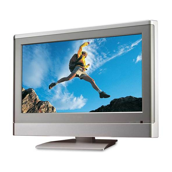
Toshiba 23HL85 Circuit Diagrams
Lcd color television
Hide thumbs
Also See for 23HL85:
- Service manual (57 pages) ,
- Owner's manual (44 pages) ,
- Specifications (2 pages)
Summary of Contents for Toshiba 23HL85
- Page 1 FILE NO. 050-200531 SERVICE MANUAL CIRCUIT DIAGRAMS LCD Color Television 23HL85 - 1 - DOCUMENT CREATED IN JAPAN, Sept., 2005 Published in Japan, Sep. 2005 (YC) TOSHIBA CORPORATION 2005...
-
Page 2: Schematic Diagram
8. SCHEMATIC DIAGRAM MODEL : 23HL85 WARNING : BEFORE SERVICING THIS CHASSIS, READ THE "SERVICE SAFETY PRECAUTIONS" ON PAGE 3 OF THIS MANUAL. CAUTION : The international hazard symbols " " in the schematic diagram and the parts list designate components which have special characteristics important for safety and should be replaced only with types identical to those in the original circuit or specified in the parts list. -
Page 3: Wiring Diagram
8-1. WIRING DIAGRAM - 58 -... -
Page 4: Block Diagram
8-2. BLOCK DIAGRAM - 59 -... - Page 5 1. Video Controller Unit & Display Data Conversion Unit The video controller unit receives the video signals inputted through the tuner, AV port (VIDEO1, VIDEO2), and converts them into an ITU656 signal through the microcomputer (VCTI) combined with the video decoder that integrates various functions in one chip.


