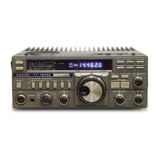
Yaesu FT-757GX Operating Manual
Hide thumbs
Also See for FT-757GX:
- Supplement manual (97 pages) ,
- Operating manual (73 pages) ,
- Technical supplement (70 pages)
Table of Contents
Advertisement
Advertisement
Table of Contents

Related Manuals for Yaesu FT-757GX


Summary of Contents for Yaesu FT-757GX
-
Page 2: Table Of Contents
TABLE OF CONTENTS GENERAL DESCRIPTION ........SPECIFICATIONS . -
Page 3: General Description
. The FT- 7 5 7GX offers full break-in QSK CW operation plus Yaesu 's new custom-designed iambic elec tronic keyer with dot memory using a 4-bit microprocessor built in, as a stand... -
Page 5: Specifications
SPECIFICATIONS TRANSMITTER Maximum FM deviation: Frequency range: ±5 kHz 160 m band 1 . 5 to 1. 99999 MHz 80 m band 3 .5 to 3 . 9 9 9 9 9 MHz Output impedance: 40 m band 7 .0 to 7 .49 999 MHz 50 ohms (nominal), unbalanced 30 m band 10.0 to 10.49999 MHz... - Page 6 GENERAL Selectivity (adjusted for maximum IF width): -6 dB -60 dB Voltage: SSB , CW(W), FSK 2. 7 kHz 4. 5 kHz 13. 5 V DC CW(N) 600 Hz l .3 kHz 6 kHz 18 kHz Power consumption: 15 kHz 30 kHz Receiver : NOTE: These figures apply as maximum band...
-
Page 7: Semiconductors
SEMICONDUCTORS Transistors Varactor diodes I Cs 2SA733AP l SVSO AN655 l 2SA733AQ 1 SV103 AN65 5 2 2SA95 2L 1 (GX) FC5 2M-5 HD10551P MB3713 2SA1012Y FC53M-5 MC335 9 2SA1193K MC14011B 2SC380TMY Zener diodes 2SC45 8B MC14013B HZ3C l 2SC45 8D MC14028B HZ4B3 2SC496Y... -
Page 8: Front Panel Controls
FRONT PANEL CONTROLS POWER This selector determines the operating mode of the This is the main on/off switch for the transceiver. transceiver. The CW-W (wide) position activates Frequency data stored in the memories and VFOs an internal AF filter, while the IF filter is the same is not affected by this switch, or by whether power as for S S B . - Page 9 not respond to weaker signals. This control also later. Clockwise rotation increases the threshold affects the squelch (SQL) control, and should be point, causing the receiver not to resp � nd to set fully clockwise when setting the squelch weaker signals. threshold point.
- Page 10 When a memory channel is recalled (as described When pressed, the displayed operating frequency later), the SOOk STEP button will be disabled, and will remain the same until the TX/RX state is the BAND/CH DWN and UP keys will then func changed (PTT line switched).
- Page 11 To the right of the ON AIR indicator are status (yellow marking) indicators for the dial lock (LOCK), split fre Note quency operation (SPLT), clarifier operation Do not press this button when operating on a (CLAR), VFO A, VFO and memory recall VFO tuned to a band different that in the o peration (MR).
- Page 12 AGC-F Pressing this button places a signal attenuator In the depresse d position, this button activates in the receiver front end, to reduce the receiver the fast AGC time constants during SSB, CW sensitivity by approximately dB when listen and AM reception; for tuning, and listening to ing to strong signals.
- Page 14 (jJ) COMP LEVEL This potentiometer sets the compression level of This RCA jack offers access to the PTT line, for the audio speech compressor during S SB trans e xternal receive/transmit switching by a foot mission with the processor on. The adj ustment switch or other device.
-
Page 15: Top Cover (Keying) Contro Ls
AF OUT This RCA jack provides constant, low-level audio transverter such as the FTV- 700. Power level is output from the receiver, unaffected by the AF approximately -6 dBm (0 .1 Vrms) at 50 ohms. gain control setting, for data decoding mo dems ®... -
Page 16: Installation
1 . 5 ) volts DC, capable o f up t o 20 amps on mentioned above and illustrated i n the diagram voice peaks. For base station installations, Yaesu on the next page, but the plastic sleeve on the o ffers a variety of AC power supplies, all of which supply DC cable mu st be cut to allow connec... - Page 17 FP-757GX FP-757HD 234V 220V 200 V 117V IOOV llO V FP-757HD POWER TRANSFORMER PRIMARY CONNECTIONS - 1 5 -...
- Page 18 Antenna Ground and Location The FT- 7 5 7GX is designed for use with any antenna In base station installations the GND terminal on system which has a 5 0-ohm resistive impedance at the rear panel of the FT-75 7GX should be con the operating frequency.
- Page 19 RED cable lead to bandwidth. Yaesu offers the RSL series of HF the POSITIVE battery terminal, and the B LACK mobile antennas. lead to the NEGATIVE terminal. The Power Plug...
-
Page 20: Interconnections
INTERCONNECTIONS 00000 000001 FP-757HO OOOC'O OOOC'O AC IOOV FP-757HO SPKA COAD CABLE B CABLE A LINEA R AMPL IFIER INTE RCON NECT ION Before connecting the linear amplifier to the However, some amplifiers use a relay coil voltage transceiver, check to be sure that the T /R relay in over 50 volts, such as the Heathkit SB-200 or SB-220, or older Henry Linears. - Page 21 LINEAR SWITCH .0.. "OFF" NON OSK LINEAR SP-102P FT-757GX 00000 00000 0000 TELEPHONE LINE LINEAR SWITCH " ON " LINEAR OPTIONAL CABLE ( T9101295A) N ote: e ay control voltage from t h ear am p l i f i er m u s t be l ess...
-
Page 22: Plug Connections
FAS-l-4R ANT A � ANTB-2 FC-757AT ofl):J::: :: :: :: Antenna Tuner B -4 Interconnections B -3 LINEAR -=-··oN·· FC-757AT PLUG CONNECTIONS DASH Stereo Headphone Plug Automatic Keyer addle Plug Manual Key or External Keyer Plug Monaural Headphone Plug ;/"' Center conductor Shield bra id Signal or Control to center pin, ground... -
Page 24: Operation
OPERATI ON Before switching on the power, check the power Power Initial Up and Tuning supply for proper connection to the transceiver, Make sure the MOX and VOX buttons are in the and proper fuse and wiring for your local AC undepressed p osition, and then press the POWER voltage (if using an AC supply), as described on button. - Page 25 Noise and Interference Reduction Except during conditions o f extreme crowding, such as during contests, the WIDTH and SHIFT The remaining controls for the receiver (except controls should be returned to the 12 o'clock the VFO and memory control keys) are provided p osition when tuning the receiver to a new fre...
- Page 26 When fast fading of SSB or CW signals occurs, the adjustment of these controls it is possible to sele ct AGC-F button may be depressed to improve receiver passbands of any width and center fre readability. The fast AGC function is also useful quency, between 0 and 600 Hz bandwidth.
- Page 27 During AM reception the noise blanker will gener RTTY ally only blank those noise pulses that are of An external RTTY modem (terminal unit) is greater amplitude than the carrier of the signal required for RTTY reception and transmission. being received, and some .distortion may be noticed Audio output from the receiver can be obtained on the received signal.
- Page 28 Yaesu strongly recommends that, The maximum power output level is determined by once initial contact has been verified, power...
- Page 29 PO and this time adjust the FWD SET control for During SSB transmission the ALC indication on full scale deflection (FWD SET mark) . Move the the meter should be monitored. Sudden shifts of FWD- REV switch back to REV, and note the peak ALC level and/or erratic ALC behavior indication on the SWR scale of the meter.
- Page 30 SSB Transmission increase in average speech power. If the p eak ALC indication on the meter goes above midrange, single sideba nd transm ission witho ut the reduce the MIC gain setting. speech processor, set the METER switch to ALC and preset the MIC gain control to midrange .
- Page 31 Set the VOX switch on the front panel to the Once contact has been established with depressed position. Set the KEYER switch on another station, power can be reduced by rotating the top panel to the MAN p osition, and close the the D RIVE control counterclockwise.
- Page 32 As mentioned in the CAUTION above for FM, AM Because of the fact that the carrier power is only transmissions should also be kept reasonably one fourth of the total PEP power of an AM signal, short, especially when using the FP-700. Reduce it must be limited to 2 5 watts or less when trans...
- Page 33 MULTI-FREQUENCY OPERATION AND MEM In this case, one VFO is used for receiving and the ORY FUNCTIONS other VFO for transmitting. The SPLIT button activates this function, and the VFO A/B button is Clarifier Operation used in conjunction with the memory buttons to Pressing the CLAR button once activates the store and recall the various transmit and receive clarifier function when operating on a VFO (A or...
- Page 34 If operation with the VFOs and memories Note: Memo ry Storage becomes confusing, it is possible to clear The eight memory channels in the FT-7 5 7GX can all VFO and memory data to the default be programmed from either VFO A or B, when frequency (7 .000.0) by switching off the operating on one of the VFOs .
- Page 35 fill the memories with a numb er of interesting operation will now be on VFO B , and the display shortwave broadcast stations that you can hear will show 7 .000.0 (unless the VFO A/B function when you tune to one of the international short has been used before) .
- Page 36 Example 2: The above technique, using the M- VFO button while operating on the memory channel to transfer Assume you are ragchewing with your friend on data into the VFOs, p reserves the frequency 20 meters, and decide that you want to check data stored in the memories for possible use later.
- Page 37 Once you have become familiar with the VFO/ the antenna system , and set the RF AMP, ATT, NB memory transfer functions used in the preceding and RF gain controls to the anticipated optimum examples, experiment with the transfer functions positions (these adjustments and settings must be to determine those most convenient and time...
- Page 38 FT-757GX H F FREQUENCY SPECTRU M CHART • Broadcast D M i l itary, G ov 't, Com m e rc i a l 0 .
- Page 39 Este manual original foi gentilmente cedido para ser digitalizado por PY2TKI Marcos Digitalizado em 24 de Novembro de 2020 por Alexandre "Tabajara" Souza, PU2SEX http://www.tabalabs.com.br http://tabajara-labs.blogspot.com MANUAL DE DISTRIBUIÇÃO GRATUITA - Respeite o meu esforço de preservar a documentacao...