Table of Contents
Advertisement
Available languages
Available languages
Quick Links
IMPORTANT INSTRUCTIONS -
: AK864L
Models
READ AND SAVE THESE INSTRUCTIONS
READ CAREFULLY BEFORE ATTEMPTING TO ASSEMBLE, INSTALL, OPERATE OR MAINTAIN THE PRODUCT DESCRIBED. PROTECT
YOURSELF AND OTHERS BY OBSERVING ALL SAFETY INFORMATION. FAILURE TO COMPLY WITH
INSTRUCTIONS COULD RESULT IN PERSONAL INJURY AND/OR PROPERTY DAMAGE!
RETAIN INSTRUCTIONS FOR FUTURE REFERENCE.
electric shock and injury to person, including the following:
1. Read all instructions before installing or using exhaust fan.
2. Use this unit only in the manner intended by the manufacturer.
If you have questions, contact the manufacturer.
3. Before servicing or cleaning the unit, switch power off at
service panel and lock the service disconnecting means to
prevent power from being switched on accidentally. When
the service disconnecting means cannot be locked, securely
fasten a prominent warning device, such as a tag, to the
service panel.
4. Installation work and electrical wiring must be done by
qualified person(s) in accordance with all applicable codes
and standards, including fire-related construction.
5. Sufficient air is needed for proper combustion and exhausting
of gases through the flue (chimney) of fuel burning equipment
to prevent back drafting. Follow the heating equipment
manufacturer's guideline and safety standards such as those
published by the National Fire Protection Association (NFPA)
and the American Society for Heating, Refrigeration, and Air
Conditioning Engineers (ASHRAE), and the local code authorities.
CAUTION:
FOR GENERAL VENTILATING USE ONLY. DO
NOT USE TO EXHAUST HAZARDOUS OR EXPLOSIVE MATERIALS
AND VAPORS.
210572097 Rev. A 8-05
OPERATING MANUAL
GENERAL SAFETY INFORMATION
When using electrical appliances, basic precautions
should always be followed to reduce the risk of fire,
SAVE THESE INSTRUCTIONS
6. When cutting or drilling into wall or ceiling, do not damage
electrical wiring and other hidden utilities.
7. Ducted fans must always be vented to the outdoors.
8. This unit must be grounded.
9. To avoid motor bearing damage and noisy and/or unbalanced
impellers, keep drywall spray, construction dust, etc. off
power unit.
WARNING:
DO NOT USE THIS FAN WITH ANY SOLID-STATE SPEED CONTROL
DEVICE.
10. Acceptable for use over a bathtub or shower when installed
in a GFCI protected branch circuit.
11. NEVER place a switch where it can be reached from a tub or
shower.
WARNING:
www.airkinglimited.com
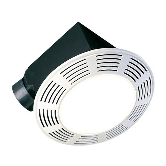
Exhaust Fan with Light
TO REDUCE THE RISK OF FIRE, ELECTRIC SHOCK,
DO NOT USE IN KITCHENS
1 of 12
Advertisement
Table of Contents

Related Manuals for Air King AK864L


Summary of Contents for Air King AK864L
-
Page 1: Important Instructions
1. Read all instructions before installing or using exhaust fan. 2. Use this unit only in the manner intended by the manufacturer. -
Page 2: Installation Instructions
(Figure 2). Screw Figure 2 4. Choose the location for your fan. To ensure the best air and sound performance, it is recommended that the length of ducting and the number of elbows be kept to a minimum, and that insulated hard ducting be used. Larger duct sizes will reduce noise and airflow restrictions. - Page 3 ALL DUCTING MUST COMPLY WITH LOCAL AND NATIONAL BUILDING CODES. 1. Connect the ducting to the fan’s duct collar (Figure 8). Secure in place using tape or screw clamp. Always duct the fan to the outside through a wall or roof cap.
- Page 4 SECTION 6 Completing the Installation 1. Reinstall the fan’s venturi by holding it at approximately a 45 degree angle, hook the two tabs on the venturi into the slots on the housing and secure in place by tightening the venturi screw.
-
Page 5: Troubleshooting Guide
Air King will not be held responsible for any bodily injury or damages to personal property or real estate whether caused directly or indirectly by the product. Some states and provinces do not allow the exclusion or limitation of incidental or consequential damages and some states do not allow limitations on how long an implied warranty lasts, so these exclusions or limitations may not apply to you. -
Page 6: Replacement Parts Diagram
REPLACEMENT PARTS DIAGRAM Qty. Description Fan Housing #8 Screw Collar Damper Blower Wheel #10 Ground Screw Polarized Nylon Receptacle 2P Polarized Receptacle Motor Plate Lock Washer Motor Motor Bracket Lock Washer Motor Nut Washer Rubber Washer Reflector Nut Lamp Holder Assembly... - Page 7 INSTRUCTIONS IMPORTANTES – MANUEL D’OPÉRATION : AK864L Modèle LIRE ET CONSERVER CES INSTRUCTIONS LIRE SOIGNEUSEMENT AVANT DE TENTER D’ASSEMBLER, INSTALLER, OPÉRER OU DE RÉPARER LE PRODUIT DÉCRIT. PROTÉGEZ VOUS-MÊME ET LES AUTRES EN OBSERVANT TOUTE L’INFORMATION DE SÉCURITÉ. FAILLIR À SE CONFORMER AUX INSTRUCTIONS PEUT RÉSULTER EN BLESSURE PERSONNELLE GRAVE ET/OU EN DOMMAGE À...
- Page 8 INSTRUCTIONS D’INSTALLATION AVERTISSEMENT: VOUS ASSURER QUE L’ALIMENTATION EST COUPÉE AU PANNEAU DE SERVICE AVANT DE COMMENCER L’INSTALLATION. SECTION 1 Préparation du Ventilateur d’évacuation 1. Sortir le ventilateur de sa boite et confirmer que toutes les pièces sont présentes. En plus du ventilateur d’évacuation vous devriez avoir: 1 - Grille avec les Lentilles de l’éclairage 1 - Ensemble de clapet (attaché)
- Page 9 Figure 6 1b. Installation des Onglets de montage: positionner le châssis contre la solive et tracer un contour du châssis sur le matériau du plafond (Figure 7). Mettre le châssis de côté et découper l’ouverture, en prenant soin de ne pas couper de câble électrique dissimulé...
- Page 10 SECTION 6 Complétion de l’installation 1. Réinstaller le venturi du ventilateur en le tenant à un angle d’environ 45 degrés, accrocher les deux onglets sur le venturi dans les fentes sur le cabinet et fixer en place en serrant les vis du venturi.
-
Page 11: Guide De Dépannage
3b. L’hélice du ventilateur frotte contre le cabinet de l’unité. Tous les produits fabriqués par Air King Limited sont garantis pour un an à partir de la date d’achat contre les défauts de main d’œuvre et/ou de matériel. De plus, tous les ventilateurs / évacuateurs, chaufferettes, combinés ventilateur/ lumière et/ou les chaufferettes et les hottes de cuisine sont garantis pour cinq années à... - Page 12 DIAGRAMME DES PIÈCES DE REMPLACEMENT Qté. Description Cabinet du ventilateur Vis #8 Collet Clapet Roue de la Soufflante Vis #10 de mise à la terre Réceptacle 2P Polarisé Réceptacle Polarisé Plaque de Moteur Rondelle de Sécurité Moteur Support de moteur Rondelle de Sécurité...