
Related Manuals for Agilent Technologies 83433A

Summary of Contents for Agilent Technologies 83433A
- Page 1 sales@artisantg.com artisantg.com (217) 352-9330 | Click HERE Find the Keysight / Agilent 83434A at our website:...
- Page 2 Agilent 83433A Lightwave Transmitter User’s Guide...
- Page 3 ❍ © Copyright material and workmanship for gies shall not be liable for any The OFF symbols Agilent Technologies 2000 a period of one year from date direct, indirect, special, inci- are used to mark the All Rights Reserved. Repro- of shipment.
- Page 4 (in which all means for protection are intact) only. W A R N I N G To prevent electrical shock, disconnect the Agilent 83433A from mains before cleaning. Use a dry cloth or one slightly dampened with water to clean the external case parts. Do not attempt to clean internally.
- Page 5 Measurement accuracy—it’s up to you! Fiber-optic connectors are easily damaged when connected to dirty or damaged cables and accessories. The Agilent 83433A front-panel OPTICAL INPUT connector is no excep- tion. When you use improper cleaning and handling techniques, you risk expensive instrument repairs, damaged cables, and compromised measurements.
- Page 6 General Safety Considerations Laser classification The Agilent 83433A is classified as an IEC LASER Class 3B according to IEC 825-1:1999-11, and an FDA LASER class 3B according to 21CFR 1040.10. The total power of light energy radiated out of the LASER OUT connector is 8.5 to 11 dBm. Opera- tor precautions are necessary to maintain safety.
-
Page 7: The Agilent 83433A-At A Glance
The Agilent 83433A is designed to produce high fidelity, low jitter waveforms for 2.488 Gb/s STM-16/OC-48, 9.953 Gb/s STM-64/OC-192 and other transmis- sion rates up through 10.7 Gb/s. The Agilent 83433A is intended for BER test- ing with error performance analyzers such as the Agilent 71612B. The Mach- Zehnder modulator is adjusted for a fixed zero chirp. -
Page 8: Table Of Contents
Front-Panel Features 2-2 Rear-Panel Features 2-4 Using a Laser Source 2-5 Performing a Quick Confidence Check 2-6 Connecting the Agilent 83433A to a Bit-Error-Ratio Test Set 2-9 Connecting the Agilent 83433A to an Oscilloscope 2-11 Reference Options 3-2 Replacement Parts 3-3... -
Page 10: Getting Started
Step 1. Inspect the Shipment 1-3 Step 2. Check the Fuse 1-5 Step 3. Connect the Line-Power Cable 1-6 Step 4. Turn on the Agilent 83433A 1-8 Step 5. Avoid costly repairs 1-9 Step 6. Learn more about our products 1-10... - Page 11 • Tips on avoiding costly repairs by proper optical connection cleaning techniques. • Lists of available accessories and power cords. • Instructions on returning your instrument to Agilent Technologies for service. • Agilent Technologies Sales and Service Offices. Chapter 4, “Specifications and Regulatory Information”...
-
Page 12: Step 1. Inspect The Shipment
Setting Up the Agilent 83433A Step 1. Inspect the Shipment N O T E The Agilent 83433A is supplied with an optical jumper cable. To avoid costly replacement, do not misplace this cable. ❒ Inspect the shipping container for damage. - Page 13 Agilent Technologies Sales Office. If the shipment was damaged, contact the carrier, then contact the nearest Agilent Technologies Sales Office. Keep the shipping materials for the carrier’s inspection. The Agilent Sales Office will arrange for repair or replace- ment at Agilent Technologies’...
-
Page 14: Step 2. Check The Fuse
Getting Started Setting Up the Agilent 83433A Step 2. Check the Fuse 1 Locate the line-input connector on the instrument’s rear panel. 2 Disconnect the line-power cable if it is connected. 3 Use a small flat-blade screwdriver to pry open the fuse holder door. -
Page 15: Step 3. Connect The Line-Power Cable
Getting Started Setting Up the Agilent 83433A Step 3. Connect the Line-Power Cable C A U T I O N Always use the three-prong AC power cord supplied with this instrument. Failure to ensure adequate earth grounding by not using this cord may cause instrument damage. - Page 16 Various power cables are available to connect the Agilent 83433A to ac power outlets unique to specific geographic areas. The cable appropriate for the area to which the Agilent 83433A is originally shipped is included with the unit. You can order additional ac power cables for use in different geographic areas.
-
Page 17: Step 4. Turn On The Agilent 83433A
The front panel LINE switch disconnects the mains circuit from the mains supply after the EMC filters and before other parts of the instrument. If the Agilent 83433A fails to turn on properly, consider the following possibili- ties: ❒ Is the line fuse good? ❒... -
Page 18: Step 5. Avoid Costly Repairs
Fiber-optic connectors are easily damaged when connected to dirty or damaged cables and accessories. The front-panel connectors of the Agilent 83433A are no exception. When you use improper cleaning and handling techniques, you risk expensive instrument repairs, damaged cables, and compromised measurements. Before you connect any fiber-optic cable to the Agilent 83433A, refer to “Cleaning Connections for Accurate... -
Page 19: Step 6. Learn More About Our Products
Setting Up the Agilent 83433A Step 6. Learn more about our products To learn more about this or any Agilent Technologies product, visit our web- site at http://www.agilent.com. To learn more about Fiber Optic Test Equipment, go to the Agilent Technolo- gies home page listed above, and follow this path: 1 Click Products. -
Page 20: Using The Agilent 83433A
Front-Panel Features 2-2 Rear-Panel Features 2-4 Using a Laser Source 2-5 Performing a Quick Confidence Check 2-6 Connecting the Agilent 83433A to a Bit-Error-Ratio Test Set 2-9 Connecting the Agilent 83433A to an Oscilloscope 2-11 Using the Agilent 83433A... -
Page 21: Front-Panel Features
Using the Agilent 83433A Front-Panel Features Front-Panel Features LASER ENABLE This key disables the Internal Class IIIB laser when in the OFF position. Be sure this key is in the OFF position before making or removing any optical connections. DATA INPUT Modulation input for digital signals. - Page 22 Using the Agilent 83433A Front-Panel Features WAVELENGTH ADJUST ENABLE Toggles between preset laser wavelength and wavelength adjust mode. (Light turns on to indi- cate you can adjust the setting using the knob.). OPTICAL OUT Provides the modulated optical output for the instrument.
-
Page 23: Rear-Panel Features
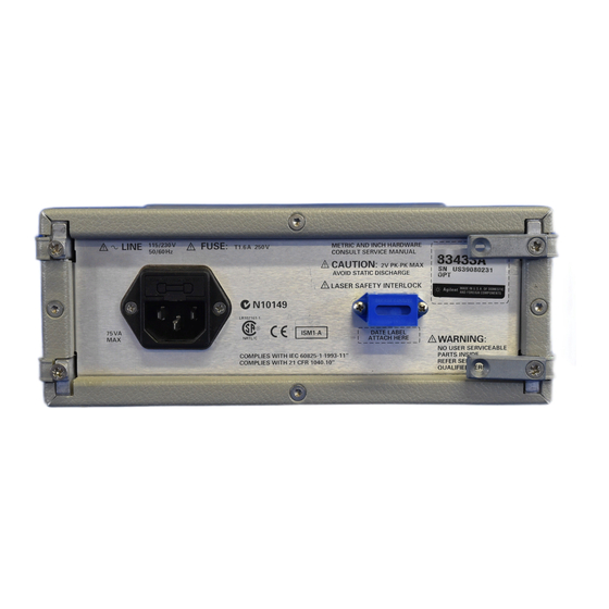
Using the Agilent 83433A Rear-Panel Features Rear-Panel Features... -
Page 24: Using A Laser Source
Using a Laser Source Using a Laser Source The Agilent 83433A contains an IEC LASER Class 3B according to IEC 60825. The total power of light energy radiated out of the LASER OUT connector is 8.5 to 11 dBm. Use caution when making or breaking connections to the front panel. -
Page 25: Performing A Quick Confidence Check
2-1. Figure 2-1. Setup to perform a quick confidence check. 2 Turn on the Agilent 83433A and let it warm up for 30 minutes. 3 Turn on the pattern generator and clock source and let them warm up according to their specifications. - Page 26 9 On the 83433A, ensure the wavelength adjust feature is disabled (front-panel LED is off). 10 Turn the LASER ENABLE key to the ON position. 11 Measure the optical power at the output of the 83433A. It will show a minimum of zero dBm.
- Page 27 (the warranty is at the front of this manual). If the lightwave transmitter is no longer under warranty or is not covered by an Agilent Tech- nologies maintenance plan, Agilent Technologies will notify you of the cost of the repair after examining the unit. Refer to “Returning the Instrument for...
-
Page 28: Connecting The Agilent 83433A To A Bit-Error-Ratio Test Set
Using the Agilent 83433A Connecting the Agilent 83433A to a Bit-Error-Ratio Test Set Connecting the Agilent 83433A to a Bit-Error-Ratio Test Set The following procedure describes how to connect the lightwave transmitter to a bit-error-ratio test set (BERT). The following equipment is used: •... - Page 29 2 Use the optical cable with Panda polarization maintaining fiber to connect the Agilent 83433A CLASS IIIb INTERNAL LASER output to the EXTERNAL LASER INPUT. 3 Adjust the optical attenuator so the power to the receiver is between 0 dBm and –16 dBm.
-
Page 30: Connecting The Agilent 83433A To An Oscilloscope
“Performing a Quick Confidence Check” on page 2-6. 2 After completing this check, connect the OPTICAL OUTPUT of the Agilent 83433A to the optical input of the oscilloscope. 3 Connect the trigger output of the pattern generator to the trigger input of the oscilloscope. - Page 32 Options 3-2 Replacement Parts 3-3 Front-Panel Fiber-Optic Adapters 3-4 Power Cords 3-5 Cleaning Connections for Accurate Measurements 3-6 Returning the Instrument for Service 3-17 Agilent Technologies Service Offices 3-20 Reference...
-
Page 33: Reference Options
Options,” on page 3-2 for a complete list of the available connector interfaces. • Optical jumper cable, Agilent part number 5022-1843. • Agilent 83433A Lightwave Receiver User’s Guide, Agilent part number 83434-90001. Available The Fiber Optics Handbook, Agilent part number 5952-9654, is an introduc- seperately tion and reference for fiber-optic measurements. -
Page 34: Replacement Parts
Reference Replacement Parts Replacement Parts Table 3-2. Replaceable Parts Description Agilent Part Nmmber APC 3.5 F-to-F (connector saver) 5061-5311 APC 3.5 50 ohm termination 1810-0118 Optical jumper cable 5022-1843 FC/PC connector interface 81000FI... -
Page 35: Front-Panel Fiber-Optic Adapters
Reference Front-Panel Fiber-Optic Adapters Front-Panel Fiber-Optic Adapters Front Panel Fiber-Optic Description Agilent Part Number Adapter Diamond HMS-10 81000AI 81000FI FC/PC 81000GI 81000KI 81000SI 81000VI Biconic 81000WI Dust Covers FC connector 1005-0594 Diamond HMS-10 connector 1005-0593 DIN connector 1005-0595 ST connector 1005-0596 SC connector 1005-0597... -
Page 36: Power Cords
Reference Power Cords Power Cords Length Plug Type Cable Part No. Plug Description Color Country (in/cm) 250V 8120-1351 Straight *BS1363A 90/228 Gray United Kingdom, 8120-1703 90° 90/228 Mint Gray Cyprus, Nigeria, Zimba- bwe, Singapore 250V 8120-1369 Straight *NZSS198/ASC 79/200 Gray Australia, New Zealand 90°... -
Page 37: Cleaning Connections For Accurate Measurements
Connectors also vary in the polish, curve, and concentricity of the core within the cladding. Mating one style of cable to another requires an adapter. Agilent Technologies offers adapters for most instruments to allow testing with many different cables. - Page 38 Reference Cleaning Connections for Accurate Measurements Figure 3-1. Basic components of a connector. Over the last few years, the FC/PC style connector has emerged as the most popular connector for fiber-optic applications. While not the highest perform- ing connector, it represents a good compromise between performance, reli- ability, and cost.
- Page 39 0.2 µm. This process, plus the keyed axis, allows very precise core-to-core alignments. This connector is found on most Agilent Technologies lightwave instruments. The soft core, while allowing precise centering, is also the chief liability of the connector.
- Page 40 Reference Cleaning Connections for Accurate Measurements Inspecting Connectors Because fiber-optic connectors are susceptible to damage that is not immedi- ately obvious to the naked eye, bad measurements can be made without the user even being aware of a connector problem. Although microscopic exami- nation and return loss measurements are the best way to ensure good connec- tions, they are not always practical.
- Page 41 Reference Cleaning Connections for Accurate Measurements Figure 3-4. Clean, problem-free fiber end and ferrule. Figure 3-5. Dirty fiber end and ferrule from poor cleaning. Figure 3-6. Damage from improper cleaning. While these often work well on first insertion, they are great dirt magnets. The oil or gel grabs and holds grit that is then ground into the end of the fiber.
- Page 42 Reference Cleaning Connections for Accurate Measurements nectors, using small glass spheres. When used with contacting connectors, these glass balls can scratch and pit the fiber. If an index matching gel or oil must be used, apply it to a freshly cleaned connector, make the measurement, and then immediately clean it off.
- Page 43 Cleaning Connectors The procedures in this section provide the proper steps for cleaning fiber- optic cables and Agilent Technologies universal adapters. The initial cleaning, using the alcohol as a solvent, gently removes any grit and oil. If a caked-on layer of material is still present, (this can happen if the beryllium-copper sides of the ferrule retainer get scraped and deposited on the end of the fiber during insertion of the cable), a second cleaning should be performed.
- Page 44 Cleaning Connections for Accurate Measurements C A U T I O N Agilent Technologies strongly recommends that index matching compounds not be applied to their instruments and accessories. Some compounds, such as gels, may be difficult to remove and can contain damaging particulates. If you think the use of such compounds is necessary, refer to the compound manufacturer for information on application and cleaning procedures.
- Page 45 Reference Cleaning Connections for Accurate Measurements Table 3-3. Cleaning Accessories Item Agilent Part Number Any commercially available denatured alcohol — Cotton swabs 8520-0023 Small foam swabs 9300-1223 Compressed dust remover (non-residue) 8500-5262 Table 3-4. Dust Caps Provided with Lightwave Instruments Item Agilent Part Number Laser shutter cap...
- Page 46 To clean an adapter The fiber-optic input and output connectors on many Agilent Technologies instruments employ a universal adapter such as those shown in the following picture. These adapters allow you to connect the instrument to different types of fiber-optic cables.
- Page 47 Reference Cleaning Connections for Accurate Measurements 3 Dry the inside of the adapter with a clean, dry, foam swab. 4 Blow through the adapter using filtered, dry, compressed air. Nitrogen gas or compressed dust remover can also be used. Do not shake, tip, or invert compressed air canisters, because this releases particles in the can into the air.
-
Page 48: Returning The Instrument For Service
Technologies Service Offices” on page 3-20 for a list of service offices. Agilent Technologies Instrument Support Center... (800) 403-0801 If the instrument is still under warranty or is covered by an Agilent Technolo- gies maintenance contract, it will be repaired under the terms of the warranty or contract (the warranty is at the front of this manual). - Page 49 4 Pack the instrument in the original shipping containers. Original materials are available through any Agilent Technologies office. Or, use the following guidelines: • Wrap the instrument in antistatic plastic to reduce the possibility of damage caused by electrostatic discharge.
- Page 50 Reference Returning the Instrument for Service rugated cardboard carton of 159 kg (350 lb) test strength. • The carton must be large enough to allow approximately 7 cm (3 inches) on all sides of the instrument for packing material, and strong enough to accom- modate the weight of the instrument.
-
Page 51: Agilent Technologies Service Offices
Agilent Technologies Service Offices Before returning an instrument for service, call the Agilent Technologies Instrument Support Center at (800) 403-0801, visit the Test and Measurement Web Sites by Country page at http://www.tm.agilent.com/tmo/country/English/ index.html, or call one of the numbers listed below. -
Page 52: Specifications And Regulatory Information
Agilent 83433A Specifications and Characteristics 4-3 Regulatory Information 4-6 Specifications and Regulatory Information... - Page 53 Specifications and Regulatory Information Specifications and Regulatory Information Specifications and Regulatory Information This chapter lists specification and characteristics of the instrument. The dis- tinction between these terms is described as follows: • Specifications describe warranted performance over the temperature range 0°C to +45°C and relative humidity <95% non-condensing (unless otherwise noted).
-
Page 54: Agilent 83433A Specifications And Characteristics
Specifications and Regulatory Information Agilent 83433A Specifications and Characteristics Agilent 83433A Specifications and Characteristics OPERATING SPECIFICATIONS Digital Data Input Data rate compatibility 2.4 to 10.7 Gb/s 0.5 to 1.5 V pk-pk Amplitude Return loss 12 dB minimum 0.1 to 5000 MHz... - Page 55 Specifications and Regulatory Information Agilent 83433A Specifications and Characteristics Modulated Optical Output Modulator insertion loss 3 to 7 dB 0 to +5.5 dBm Optical power output 27 dB minimum Output return loss 12 dB minimum Extinction ratio Jitter generation 0.15 UI pk-pk max.
- Page 56 Specifications and Regulatory Information Agilent 83433A Specifications and Characteristics Radiated and conducted emissions are in compliance with the requirements of CISPR Publication 11, Class A and immunity in compliance with IEC 61326-1 a. AC coupled. b. Input power greater than +10 dBm may cause modulated optical output power to exceed Class I level.
-
Page 57: Regulatory Information
Specifications and Regulatory Information Regulatory Information Regulatory Information • Laser Classification: This product contains an IEC LASER Class 3B according to IEC 60825-1 Title 21 Part 1040. • This product contains an FDA laser Class IIIb according to 21CFR 1040.10. •... - Page 58 Specifications and Regulatory Information Regulatory Information Declaration of Conformity...
- Page 60 Index accessories, 3-2 external laser input, 2-3 adapters, 2-3 fiber optic, 3-4 adjusting fiber optics wavelength, 2-2 adapters, 2-3, 3-4 Agilent offices, 3-20 cleaning connections, 3-6 connectors, covering, 3-18 fiber optics handbook, 3-2 BERT foam swabs, 3-14 connecting to, 2-9 front panel bit-error-ratio test set, 2-9...
- Page 61 Index sales and service offices, 3-20 shipping maintenance contract, 2-8 procedure, 3-18 measurement spare fuse, 1-5 accuracy, iv specifications definition of terms, 4-2 swabs, 3-14 noise declaration, 4-6 using a laser source, 2-5 optical out connector, 2-3 oscilloscope connecting to, 2-11 verification test failing, 2-8 verifying...