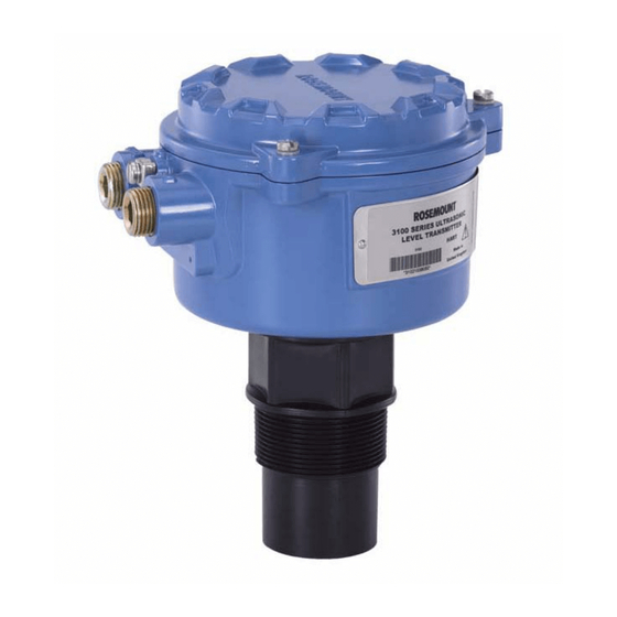
Emerson Rosemount 3101 Quick Start Manual
Ultrasonic liquid level transmitters
Hide thumbs
Also See for Rosemount 3101:
- Quick start manual (32 pages) ,
- Reference manual (240 pages) ,
- Reference manual (144 pages)

Related Manuals for Emerson Rosemount 3101


Summary of Contents for Emerson Rosemount 3101
- Page 1 Quick Start Guide 00825-0100-4840, Rev CD August 2019 ™ Rosemount 3101, 3102, and 3105 Ultrasonic Liquid Level Transmitters...
-
Page 2: Table Of Contents
Quick Start Guide August 2019 Contents About this guide...........................3 The Rosemount 3101, 3102, and 3105..................5 Considerations before installation....................7 Electrical installation........................10 Configuring the transmitter....................... 21 Product Certifications.........................36 www.emerson.com... -
Page 3: About This Guide
August 2019 Quick Start Guide About this guide This installation guide provides basic guidelines for the Rosemount 3101, 3102, and 3105 Ultrasonic Level Transmitters. It does not provide instructions for detailed configuration, diagnostics, maintenance, service, troubleshooting, or installations. Refer to the Rosemount 3101, 3102, and... - Page 4 Physical security is an important part of any security program and fundamental to protecting your system. Restrict physical access by unauthorized personnel to protect end users’ assets. This is true for all systems used within the facility. www.emerson.com...
-
Page 5: The Rosemount 3101, 3102, And 3105
August 2019 Quick Start Guide The Rosemount 3101, 3102, and 3105 The Rosemount 3101, 3102, and 3105 are 4–20 mA loop-powered level transmitters designed for continuous liquid level measurements in tanks or open flow channels. They can be connected directly to a plant control system, or used with a Rosemount 3490 Series Control Unit for programmable control functionality. - Page 6 August 2019 Figure 2-1: Typical Application 20mA Rosemount 3100 Series Transmitter Rosemount 3490 Series Control Unit 4–20 mA signal Relay Pump Bottom reference 4–20 mA and HART signal Note HART is available on the Rosemount 3102 and Rosemount 3105. www.emerson.com...
-
Page 7: Considerations Before Installation
August 2019 Quick Start Guide Considerations before installation The Rosemount 3100 Series may be used for level and volume measurement in open or closed tanks, or open channel flow measurement. The glass-filled nylon housing version of the transmitter must be installed in a location where it is protected from ultraviolet radiation to prevent long term degradation of the plastics used (e.g., shrouded from direct sunlight). - Page 8 • The Rosemount 3105 transmitter is Intrinsically Safe (IS) approved for hazardous area installations. • The Rosemount 3101, 3102, and 3105 are designed for open or closed tank installation. They are weatherproof and protected against the ingress of dust. •...
- Page 9 August 2019 Quick Start Guide • To avoid detecting unwanted objects in the tank or well, it is advisable to maintain a distance sideways of at least 1.3-in. from the center line of the transmitter for every foot (11 cm per meter) range to the obstruction (Figure 4-5).
-
Page 10: Electrical Installation
The 3105: 12 to 40 Vdc(non-hazardous area), 12 to 30 Vdc (hazardous area) Note • To comply with the CSA approval requirements, the Rosemount 3101 and 3102 must be powered from a Rosemount 3490 Series Control Unit or a class 2 separate extra-low voltage (SELV) source. •... - Page 11 4.1.2 Connect the cable(s) to the transmitter Note • The Rosemount 3101 and 3102 are not intrinsically safe and are for use in non-hazardous (Ordinary Location) installations only. • If HART communications are required (available on the Rosemount 3102 and 3105), a 250 Ohm (minimum), 0.25 W load resistor must be installed in the loop.
- Page 12 AWG); maximum: 1.5 mm (16 SWG/18 AWG) E. Minimum of 12 Vdc is required at the transmitter for it to operate F. Transmitter terminals: 1(+): +24 Vdc 2(-): 0 Vdc 3+4: Relay 1(SPST) 5+6: Relay 2 (SPST) 7+8: Remote temperature sensor www.emerson.com...
- Page 13 August 2019 Quick Start Guide Figure 4-3: Wiring Diagram for Rosemount 3105 0 Vdc A. Maximum cable length is 9,750 ft. (3,000 m) B. Connect the cable shield/screen to ground (earth) in the control room C. Cable thickness: Ø0.15 to 0.31 in. (Ø4 to 8 mm) D.
- Page 14 To help with an installation, flange accessories and bracket kits are available from Emerson. The accessory flanges supplied are manufactured from PVC and are a full face design. Care must be taken when installing to raised face mating flanges on the tank or vessel to prevent distortion of the PVC flange...
- Page 15 August 2019 Quick Start Guide Figure 4-4: Bracket Mounting A. Stainless steel bracket B. No. 4X 13 long self tap screws (x3), carbon steel (zinc plated) C. PVC disc Procedure 1. Attach bracket to the disc using the three screws provided. 2.
- Page 16 Procedure 1. If the tank has a flanged nozzle or stand-off: The instrument (accessory) flanges supplied by Emerson are manufactured from PVC and are a full face design. Care must be taken when installing to a raised face mating flange on the tank or vessel to prevent distortion of the PVC flange by overtightening the bolts.
- Page 17 August 2019 Quick Start Guide If mating to a raised face flange (RF) on the tank nozzle or stand-off, tighten to a maximum torque of 10 lb-ft (13.6 N-m) 2. If the tank has a threaded nozzle or stand-off: a) Attach the transmitter to the nozzle/stand-off using the threaded connection.
- Page 18 B. Hmax C. Transmitter bottom reference = H + 12.2-in. (300 mm) + 2-in. (50 Note It is important that the bottom reference of the transmitter should be related to the datum of the primary measuring device (Figure 4-7). www.emerson.com...
- Page 19 August 2019 Quick Start Guide Figure 4-7: Bottom Reference of a Flume or Weir Transmitter bottom reference Primary device (e.g. flume, weir) invert Approach channel Flow direction Note When setting the bottom reference on a ‘V’- notch weir (Figure 4-8), it is important the true invert is used and not the meniscus level.
- Page 20 The Rosemount 3102 and Rosemount 3105 have the option of a Remote Temperature Sensor (RTS). This temperature sensor should be mounted in a location where it can get an accurate air temperature measurement and is protected from sunlight. (See Quick Installation Guide for further RTS installation information). www.emerson.com...
-
Page 21: Configuring The Transmitter
August 2019 Quick Start Guide Configuring the transmitter Each transmitter can be configured and verified using the integral buttons. Alternatively, the Rosemount 3102 and Rosemount 3105 can be configured and verified using a Field Communicator, Rosemount 3490 Series Control Unit, or a PC running AMS Device Manager (see Figure 5-1). - Page 22 G. AMS Device Manager H. Control system 751 Display Transmitter base units The Base Units for the Rosemount 3101 are always metric, but changing the Display Units re-scales the level measurement from meters-to-feet or meters-to-inches (see Transmitter display units/primary variable units (P012)).
- Page 23 5.1.1 Use the integral buttons to change the base units on the Rosemount 3102 and 3105 (The Rosemount 3101 always operates in meters. See Transmitter display units/primary variable units (P012) for how to change Display Units). To change the Base Units on the Rosemount 3102 and 3105, use the following procedure.
- Page 24 4. Select new base units. 5. To get the same base units on the control unit, switch the power off and then on again. The control unit prompts for the transmitter’s Bottom Reference value in the new base units. www.emerson.com...
- Page 25 Note This parameter is important for calibrating and configuring the transmitter. On the Rosemount 3101, the transmitter’s bottom reference setting is the distance measured vertically along the ultrasonic beam path from the transmitter face to the zero level of a tank or an open channel (see...
- Page 26 Figure 5-5: Rosemount 3491 Screen Procedure 1. From the Main Menu screen, select SETUP. 2. Select the transmitter (e.g., Tx1: 3102). 3. Select DUTY and then select Bottom Ref. 4. Follow the on-screen instructions to input and save the new setting. www.emerson.com...
- Page 27 Quick Start Guide Transmitter duty/tank shape P011/non-linear profile P011 The instructions here are for selecting level measurement on the Rosemount 3102 and 3105. The Rosemount 3101 duty is always level measurement. For advanced applications, refer to the Rosemount 3100 Series Reference Manual.
- Page 28 Transmitter display units/primary variable units (P012) • On the Rosemount 3101, display units are indicated by the position of the decimal point in the displayed PV value (i.e., 8.000 (m), 26.24 (ft.), or 314.9 (in.)). The 3101 measures and calculates in meters. The measured value is converted into the selected display units using a pre- programmed conversion factor.
- Page 29 5.4.1 Use the integral buttons to change the display units on the Rosemount 3101 The Rosemount 3101 measures and calculates in meters. The display units are derived as a last operation using a pre-programmed conversion factor. Procedure 1. Starting from the PV display, hold down the blue button → and do not release it.
- Page 30 5. Press the blue button → to move to the next digit. The selected digit flashes. 6. Repeat steps 5 and 6 until the last digit is flashing and edited as required. 7. Press the blue button → to confirm the new value. The flashing stops. www.emerson.com...
- Page 31 August 2019 Quick Start Guide Press the red button ↵ to save the new value. The next menu • appears. Press the blue button → to not save. The SCALE menu appears. • 5.5.2 Use the Field Communicator or AMS Device Manager to view or change the scale factor (P013) Figure 5-10: Field Communicator Screen PV Scale Factr P013...
- Page 32 Quick Start Guide August 2019 4 mA and 20 mA output (on the Rosemount 3101 only) The process value (e.g. liquid level) is indicated by the 4–20 mA output. Figure 5-12: Tank Geometry (on the Rosemount 3101 only) 4-20mA 20mA...
- Page 33 August 2019 Quick Start Guide 5.6.1 Use the integral buttons to change the level at 4mA Procedure 1. From the PV display, press the green button ↓ repeatedly until 4 is shown. 2. Press the blue button → to indicate the present value of the 4 mA level.
- Page 34 Level SV Distance TV (D902) 3, 2, 1, 3 MONITOR,[Tag], READINGS, VARIABLES, Distance TV Distance (D910) 3, 1, 2, 1, 1 MONITOR,[Tag], DIAGNOSTICS, Distance Configure this parameter if not communicating HART variables (PV, SV, TV, and FV) to a Host. www.emerson.com...
- Page 35 August 2019 Quick Start Guide Figure 5-13: Tank Geometry (Rosemount 3102 and 3105 only) 4-20mA/HART 20mA Rosemount 3490 Series Control Unit Bottom Liquid level Distance (D910) Tank reference point Level offset Lower blanking Distance TV (D902) Distance offset (P060) Upper blanking (P023) Level SV (D901) Sensor reference point User preferred sensor reference point...
-
Page 36: Product Certifications
The most recent revision of the EU Declaration of Conformity can be found at Emerson.com/Rosemount. Factory Mutual (FM) approvals 6.2.1 Factory Mutual (FM) ordinary location approval (Rosemount 3101 and 3102 only) Project ID: 3024095 The transmitter has been examined and tested to determine that the design... - Page 37 Standards Council of Canada (SCC). Special condition for safe use: The power for the Rosemount 3101 and 3102 must be supplied from a Rosemount 3490 Series Control Unit or a class 2 separate extra-low voltage (SELV) source.
- Page 38 II 1 G, Ex ia IIC T6 Ga (Ta = –40 to 55 °C) II 1 G, Ex ia IIC T4 Ga (Ta = –40 to 60 °C) Entity parameters: Ui = 30 V, li = 120 mA, Pi = 0.82 W Li = 108μH, Ci = 0 nF www.emerson.com...
- Page 39 August 2019 Quick Start Guide NEPSI China intrinsic safety approval (on the Rosemount 3105 only) Certificate number: GYJ081008X Markings: Ex ia IIC T6 (Ta = –40 to 55 °C) Ex ia IIC T4 (Ta = –40 to 60 °C) Entity parameters: Ui = 30 V, li = 120 mA, Pi = 0.82 W, Li = 108μH, Ci = 0 nF IECEx intrinsic safety approval (Rosemount 3105 only)
- Page 40 II 1 G, Ex ia IIC T4 Ga (Ta = –40 to 60 °C) II 1 G, Ex ia IIC T6 Ga (Ta = –40 to 55 °C) IECEx: Ex ia IIC T6 Ga (Ta = –40 to 55 °C) Ex ia IIC T4 Ga (Ta = –40 to 60 °C) www.emerson.com...
- Page 41 August 2019 Quick Start Guide Electrical: Ui = 30 V, li = 120 mA, Pi = 0.82 W Li = 108 μH, Ci = 0 μF Year of manufacture: printed on the product label Special conditions for safe use: • The equipment must not be installed directly in any process where the enclosure might be charged by the rapid flow of non-conductive media.
- Page 42 Quick Start Guide August 2019 Declaration of conformity Declaration of conformity for Rosemount 3100 Series Ultrasonic Level Transmitters. Figure 6-1: EU Declaration of Conformity www.emerson.com...
- Page 43 August 2019 Quick Start Guide Quick Start Guide...
- Page 44 Quick Start Guide August 2019 China RoHS www.emerson.com...
- Page 45 August 2019 Quick Start Guide Quick Start Guide...
- Page 46 Quick Start Guide August 2019 www.emerson.com...
- Page 47 August 2019 Quick Start Guide Quick Start Guide...
- Page 48 The Emerson logo is a Twitter.com/Rosemount_News trademark and service mark of Emerson Electric Facebook.com/Rosemount Co. Rosemount is a mark of one of the Emerson Youtube.com/user/ family of companies. All other marks are the RosemountMeasurement property of their respective owners.