Table of Contents
Advertisement
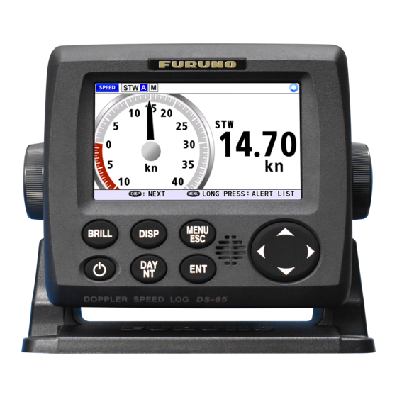
Installation Manual
DOPPLER SPEED LOG
DS-85
Model
SAFETY INSTRUCTIONS ................................................................................................ i
SYSTEM CONFIGURATION ........................................................................................... ii
EQUIPMENT LISTS........................................................................................................ iii
1. MOUNTING..............................................................................................................1-1
1.1 Display Unit........................................................................................................................1-1
1.2 Distributor Unit ...................................................................................................................1-5
1.3 Transceiver Unit.................................................................................................................1-6
1.4 Transducer.........................................................................................................................1-8
1.5 Option Unit .......................................................................................................................1-22
2. WIRING....................................................................................................................2-1
2.1 Overview ............................................................................................................................2-1
2.2 Precautions for Cable Installation ......................................................................................2-2
2.3 Display Unit........................................................................................................................2-2
2.4 Distributor Unit ...................................................................................................................2-5
2.5 Transceiver Unit...............................................................................................................2-10
2.6 Junction Box (option) .......................................................................................................2-12
2.7 Grounding ........................................................................................................................2-14
3. ADJUSTMENTS ......................................................................................................3-1
3.1 [EQUIPMENT] sub menu...................................................................................................3-3
3.2 [I/O] sub menu ...................................................................................................................3-6
3.3 [SIMULATION] sub menu ..................................................................................................3-7
3.4 [MAINTENANCE] sub menu ..............................................................................................3-8
3.5 [TEST] menu....................................................................................................................3-12
3.6 [DS-8510 DATA]/[DS-8520 DATA] sub menu..................................................................3-20
3.7 [EQUIP RESET] sub menu ..............................................................................................3-20
3.8 How to Set SFI.................................................................................................................3-20
3.9 How to Offset for Analog Port ..........................................................................................3-21
APPENDIX 1 JIS CABLE GUIDE .............................................................................AP-1
APPENDIX 2 DIGITAL INTERFACE .......................................................................AP-2
APPENDIX 3 CALIBRATION....................................................................................AP-7
PACKING LISTS ......................................................................................................... A-1
OUTLINE DRAWINGS ................................................................................................ D-1
INTERCONNECTION DIAGRAM ................................................................................ S-1
www.furuno.com
All brand and product names are trademarks, registered trademarks or service marks of their respective holders.
Advertisement
Table of Contents

Related Manuals for Furuno DS-8500


Summary of Contents for Furuno DS-8500
-
Page 1: Table Of Contents
APPENDIX 1 JIS CABLE GUIDE ................AP-1 APPENDIX 2 DIGITAL INTERFACE ...............AP-2 APPENDIX 3 CALIBRATION..................AP-7 PACKING LISTS ......................A-1 OUTLINE DRAWINGS ....................D-1 INTERCONNECTION DIAGRAM ................S-1 www.furuno.com All brand and product names are trademarks, registered trademarks or service marks of their respective holders. - Page 2 The paper used in this manual is elemental chlorine free. ・FURUNO Authorized Distributor/Dealer 9-52 Ashihara-cho, Nishinomiya, 662-8580, JAPAN A : MAY 2020 Printed in Japan All rights reserved. B1 : DEC . 01, 2020 Pub. No. IME-72880-B1 (AKMU ) DS-85...
-
Page 3: Safety Instructions
The tank shall be strong enough to withstand the water pressure in fully loaded conditions in rough weathers. FURUNO Electric Co., Ltd. is not liable to any loss of ship and personnel which is caused by installation procedures. -
Page 4: System Configuration
Sub display RD-501* 1Ø, 50/60 Hz RD-50 or RD-20 or DIMMER DS-8500 DIMMER CONTROLLER CONTROLLER RD-502* RD-502 Sub display : Not available for DS-8500 RD-20 or Nav Equipment DS-8500 (LAN) IEC61162-450 DIMMER RANGE Nav Equipment ANALOG (POWER FAIL) SELECTOR* DISPLAY... -
Page 5: Equipment Lists
DS-8510-2-LIF – For 200 VDC, w/LIF board Transceiver Unit DS-8520 – Transducer DS-8530 – 10/20/30/40 m cable Installation Materials CP05-13701 001-426-520 For DS-8500 CP65-01501 001-569-940 For DS-8510 CP65-01401 001-569-870 For DS-8520 Spare Parts SP65-01101 001-569-930 For DS-8510 SP65-01001 001-569-860 For DS-8520... - Page 6 DS-854 — Ball valve type, replaceable on sea Front Fixing Panel OP24-35 001-247-240 For DS-8500 Waterproof Kit OP05-139 001-426-500 For waterproof of DS-8500 Replacement Kit OP05-140 001-426-510 For retrofit of display unit from DS-800 to DS-8500 F_Mount OP05-141 001-436-880 For DS-8500...
-
Page 7: Mounting
MOUNTING NOTICE Do not apply paint, anti-corrosive sealant or contact spray to coating or plastic parts of the equipment. Those items contain organic solvents that can damage coating and plastic parts, especially plastic connectors. Display Unit The display unit (main or sub) can be installed on a desktop, overhead, on the bulk- head or flush mounted in a console or panel. - Page 8 1. MOUNTING Grounding Ground the unit with the supplied ground wire referring to Back view the figure to the right. Ground terminal 1.1.2 How to fit the cable gasket (When using the OP05-146-1 or OP05-146-2) When using the cable assembly OP05-146-1 (5 m) or OP05-146-2 (10 m), its water- proofing capability can be increased by attaching the cable gasket attached to the ca- ble assembly.
- Page 9 1. MOUNTING 2. Fit the cable gasket to the cable clamp, referring to the figure below. 1. Fit the cable gasket to the cable clamp, 2. To pass the fixing lip completely passing the fixing lip partially through through the cable gasket, twist the the cable clamp.
- Page 10 1. MOUNTING 3. Secure the hanger to the desktop or overhead with four self-tapping screws (φ5×20, installation material). The hanger should be oriented with the insertion slots facing forward. For mounting dimensions and required clearance, see the outline drawing at the back of this manual. Desktop installation Overhead installation 4.
-
Page 11: Distributor Unit
1. MOUNTING 6. Run the cabling through the cutout, then, referring to section 2.3.2, connect the necessary cabling to the display unit. Mounting hole Mounting hole DISPLAY UNIT DISPLAY UNIT F Mount F Mount Cushion Cushion Front panel Front panel Self-tapping screws (ø3×20, 4 pcs) Self-tapping screws (ø3×20, 4 pcs) 7. -
Page 12: Transceiver Unit
1. MOUNTING 1.2.2 Mounting Use M6 (supplied) or M8 (local supplied) screws. Note that the size of mounting holes etc. differ according to the screw size. Note: For bulkhead installations, the cable entry must face downward. 1. Make four pilot holes, referring to the outline drawing at the back of this manual. 2. - Page 13 1. MOUNTING • Leave sufficient space at the sides and rear of the unit to facilitate maintenance. • A magnetic compass will be affected if the processor unit is placed too close to the magnetic compass. Observe the compass safe distances in the "SAFETY INSTRUCTIONS"...
-
Page 14: Transducer
1. MOUNTING Transducer The performance of this equipment is directly dependent on the installation of the transducer. The installation of the transducer and the tank should be accomplished by a dockyard referring to the installation drawings at the back of this manual. Also, the transducer DS-820 which is used for DS-80 is available. - Page 15 1. MOUNTING • Refer to the procedure below for the location where the supplied liquid gasket TB1121 is applied. For DS-781 (projection type) bottom tank, there is no place to apply the liquid gasket. 1.4.2 How to install the transducer DS-784 (Mounting of Flush Type Seachest) The seachest DS-784 is delivered temporarily assembled with the transducer.
- Page 16 1. MOUNTING DS-786 (Mounting of Gate Valve Type Seachest) Gate valve DS-786 (Sectional view) Note: The gate valve requires service space of 700 mm. For details, see the installa- tion drawing at the back of this manual. 1. Unfasten M16 nut (3) and spring washer (11) from the assembled gate valve to remove the follow- Shaft assy.
- Page 17 1. MOUNTING 5. Apply Kinoruster (supplied) to the hollow side of the flange (3). 6. Clean the top and bottom of the gate valve (20), and put it on the gasket1 (18) set on the flange (3). 7. Fasten M16 nut (10) and M16 spring washer (11) loosely to the stud bolt of the flange (3).
- Page 18 1. MOUNTING 14. Apply Three Bond to the thread part of hex. bolt (15) with seal washer (16) and use them to fasten the transducer. Check that the fore mark on the shaft is aligned with the projection at the bottom of the transducer. The fore mark on the shaft Align them.
- Page 19 1. MOUNTING 20. Use the M16 hex. bolt (12), M16 nut (10) and M16 spring washer (11) to fasten the flange (4) loosely. 21. Insert the shaft so the projection on the transducer fits in the groove on the flange (3).
- Page 20 1. MOUNTING mm, be sure to check that the hollow side of the flange (3) is aligned with the pro- jection on the transducer (1). Gland (19) Hex. bolt (13)(M8x30) Spring washer (14)(M8) Fixing plate (21) 0-3 mm Lock ring (6) 27.
- Page 21 1. MOUNTING DS-781 (Mounting of Projection Type Seachest) 1. Weld doubling plate (sup- plied by shipyard) to hull plate. 2. Remove the M10 bolts, and take out transducer fixing flange (2) (including trans- ducer) from transducer housing (1). 3. Determine the projection distance, and cut transducer housing (1).
- Page 22 1. MOUNTING DS-854 (Ball valve, Transducer) 13 14 7 8 19 13 14 13 14 10 11 15 16 9 10 11 Ball valve DS-854 (Sectional view) Note 1: The liquid gasket for installation may not be supplied due to export regula- tions.
- Page 23 1. MOUNTING Note: Do not paint the top side of the flange (3) and handle it carefully to preserve the waterproofing. 3. Weld the flange (3) to the ship’s hull. The welding and doubling methods are left up to the shipyard. 4.
- Page 24 1. MOUNTING 10. Remove the Jubilee clip located at the base of the transducer (1) cable and four M4 flat-head Phillips screws at the top side of the transducer (1). Jubilee clip Jubilee clip Do not remove this screw. Remove these four screws.
- Page 25 1. MOUNTING 15. Fasten the gland (19) to the top of the shaft (5). Gland (19) Flat washer (8) Gasket (7) Flat washer (8) The fore mark on the shaft Flange (4) Hex. nut (15)(M4x16) Seal washer (16)(M4) Check that they Apply Liquid Gasket (TB1121) here.
- Page 26 1. MOUNTING 21. Tighten the M16 nut (8 pcs.) on the ball valve (20). Hex. bolt (13)(M8x30) Spring washer (14)(M8) Hex. bolt (13)(M8x30) Spring washer (14)(M8) Hex. bolt (13)(M8x30) Spring washer (14)(M8) Lock ring (6) Hex. bolt (12)(M16x60) Align the hollow side of the spacer (3) with Flange (4) the projection on the...
- Page 27 1. MOUNTING 25. Put the fixing plate (21) between the shaft (5) and gland (19). Fasten the plate with two sets of M8 hex. bolt (13) and M8 spring washer (14). Check the clearance between the fixing plate (21) and the lock ring (6). If the clear- ance is more than 3 mm, be sure to check that the hollow side of the flange (3) is aligned with the projection on the transducer (1).
-
Page 28: Option Unit
1. MOUNTING 2. Attach the supplied handle to the square projection and then turn the handle 90° to change the stopper position. Stopper Stopper Handle Handle Valve: OPEN Bolt Bolt Square projection Square projection Valve: CLOSE 3. After opening or closing the ball valve, tighten the removed nuts until the handle Gasket CR cannot be turned. - Page 29 1. MOUNTING 1.5.2 Range Selector Change analog output to allow analog scales of -2 to 6 kn in addition to -10 to 30 kn. Installation considerations • The temperature and humidity of the mounting location should be moderate and stable. •...
- Page 30 (100-115 VAC or 200-220 VAC) vary depending on the type used. RD-502 The RD-502 is used for controlling the illumination of the display unit DS-8500 and the sub display unit (option). For the connection between RD-502 and RD20/RD-50, refer to the operator’s manual of each remote display (RD-20: OME-44540, RD-50: OME-44530).
-
Page 31: Wiring
CONTROLLER DIMMER max. 30 m RD-502 CONTROLLER Sub display TTYCSLA-4 RD-502* RD-20 or max. 50 m Nav Equipment DTI-C5E350 VCV : Unavailable for DS-8500 DS-8500 (LAN) 10/20/30 m IEC61162-450 TTYCSLA-1 ANALOG DISPLAY DPYC(Y)-1.5 Nav Equipment RANGE UNIT (POWER FAIL) max. 100 m... -
Page 32: Precautions For Cable Installation
Using the supplied terminals on the inside of the DS-8500, fit the drain wire (or shield line) of each cable with a terminal, then attach the terminal to the inside of the DS-8500 (the same place it was situated originally). - Page 33 2. WIRING 2.3.2 How to connect the cables 1. Unfasten the four screws on the rear cable clamp, then remove the cable clamp to reveal the WAGO connector. WAGO connector Cable clamp Cable clamp The cable clamp must be oriented as shown in this figure. 2.
- Page 34 2. WIRING Note: To satisfy the requirements for IPX5 waterproof rating, the cable used must have a diameter of 14.4 mm (±0.4 mm). 1. Unfasten the four screws on the rear cable clamp, then remove the cable clamp to reveal the WAGO connector. 2.
-
Page 35: Distributor Unit
2. WIRING Distributor Unit 2.4.1 Required tools The following item should be prepared in advance for this installation locally. Item Remarks Equivalent of Convex CV-150B (125 × 4.9 mm) Cable tie 2.4.2 How to fabricate the cables Note: Make sure that the cover does not contact any connected cables when you close the cover. - Page 36 2. WIRING DPYC(Y)-1.5 for Ship’s Mains 30 30 Inner Inner Armor sheath sheath Vinyl tape Attach the crimp-on lug to the core. LAN cable DTI-C5E350 VCV Note: This equipment only Cable jacket Armor uses straight cables. Inner vinyl sheath Outer vinyl sheath Wrap vinyl tape.
- Page 37 2. WIRING 2.4.3 How to connect the cables Some parts or wiring have been omitted from the illustrations for clarity. Note: When closing the distributor unit, make sure that the connected cables do not contact the cover. How to open/close the top cover Unfasten nine screws to open the top cover.
- Page 38 2. WIRING Cable entrance viewed from inside of the distributor unit Also, the lane for each cable is shown below, referring to the Wiring Label attached on the reverse side of the top cover. Cable connection (other than the power cable) Connect the cables to the connectors on the DST board 65P6110 and the LIF board 65P6111 (option).
- Page 39 2. WIRING Printed board No. of cable Signal Remarks Connector entrance Type TRX POWER 65P6110 Power to transceiver (DST) unit Signal from trans- ceiver unit SUB DISP1 DISP SUB DISP2 IEC61162OUT3 IEC61162IN1 IEC61162IN2 IEC61162OUT1 CN10 IEC61162OUT4 CN11 DIMMER CN12 POWER FAIL CN13 IEC61162OUT2 CN14...
-
Page 40: Transceiver Unit
2. WIRING Transceiver Unit 2.5.1 How to fabricate the cables Attach the SC lock and the packing (pre-attached to the cable entry on the transceiver) to the cable before fabricating the cable. Please pay attention to the orientation of the SC lock and packing. - Page 41 2. WIRING Transducer cable Outer sheath (Armor for cable with no outer sheath) Outer sheath (Armor for cable with no outer sheath) Shield Shield Aluminum tape Aluminum tape SC lock SC lock Gasket Gasket (Do not remove this tape.) (Do not remove this tape.) Wrap the aluminum tape.
-
Page 42: Junction Box (Option)
2. WIRING Terminal for power Clamp Clamp Shield SC lock SC lock Signal cable Transducer (From distributor unit) cable • Signal cable (from distributor unit): Connect the power and signal lines, and fix the cable on the conductive tape with the clamp in the transceiver unit. Then tighten the cable with the SC lock. - Page 43 2. WIRING After tightening the inner sheath by the gland, wind a grounding wire on the armor as shown below. Then connect the grounding wire to the wing nut on the front of the chas- sis. Gland Gasket Armor Inside of the junction box Outer sheath Outer sheath...
-
Page 44: Grounding
2. WIRING Grounding This equipment uses pulse signals which may cause interference to other electronic equipments It is strongly recommended to ground all cables referring to the guidelines below. • Separate all units as far as possible from radio equipment. •... -
Page 45: Adjustments
ADJUSTMENTS At the first start-up after installation, turn on the display unit with the power key. Open the protect- ed menus to adjust the system. Follow the proce- dures in this chapter to complete the adjustment. DAY/NT Power key Transducer initial setting For the main display unit, the [XDCR INIT SET] display is shown when the power is turned on. - Page 46 3. ADJUSTMENTS [MENU]→[DISP]→[BRILL] key How to select the language for menu window The default language for the menu window is English. To change the language to Jap- anese, set as follows. 1. Press the MENU/ESC key to open the main menu. 2.
-
Page 47: Equipment] Sub Menu
3. ADJUSTMENTS 4. Enter the password (ENT key × 6 times) to open the sub menu. The [EQUIP- MENT] menu has the eight sub menus shown in the figure below. [EQUIPMENT] sub menu Option menus 5. Close the menu by pressing the MENU/ESC key once or click the left button a few times. - Page 48 3. ADJUSTMENTS 3.1.1 [TRANSDUCER] menu On the [EQUIPMENT] sub menu, select [TRANSDUCER] to open the [TRANS- DUCER] menu. [TYPE] Shows the type for the transducer which is set the transducer initial setting. See page 3-1 for the transducer initial setting. To change the type, execute [TYPE CLEAR] then set the transducer settings again.
- Page 49 3. ADJUSTMENTS 3.1.2 [TRIM] menu On the [EQUIPMENT] sub menu, select [TRIM] to set the correction for ship an- gle. The setting range is -12.5° to 12.5° (de- fault: 0°). 3.1.3 [EXTERNAL KP] menu On the [EQUIPMENT] sub menu, select [EXTERNAL KP] to set up external KP.
-
Page 50: I/O] Sub Menu
3. ADJUSTMENTS [I/O] sub menu On the main menu, select [EQUIPMENT] →[I/O] to open the [I/O] sub menu. [EQUIPMENT] sub menu Option menus 3.2.1 [ALERT MODE] menu On the [I/O] sub menu, select [ALERT MODE] to set the alert mode, [LEGACY], [ALERT I/F1] , [ALERT I/F2] and [ALERT I/F3](default: [ALERT I/F1]). -
Page 51: Simulation] Sub Menu
3. ADJUSTMENTS [FORMAT] Select the format for LAN connection, [IEC Ed.4] or [IEC Ed.5] (default: [IEC Ed.5]). [TRANSMISSION GROUP SETUP] Open the [TRANSMISSION GROUP SETUP] window to set the IP address or port. [IP ADDRESS]: Set the IP address, [000.000.000.000] to [255.255.255.255] (default: [239.192.000.004]). -
Page 52: Maintenance] Sub Menu
3. ADJUSTMENTS SIM MODE Select [ON] to activate the simulation mode. SIM SPEED Select the speed to output from the transceiver unit in simulation mode. The setting range is [-10.0] to [40.0] kn (de- fault: [+10.0] kn). [MAINTENANCE] sub menu On the main menu, select [EQUIPMENT] →[MAINTENANCE] to open the [MAINTE- NANCE] sub menu. - Page 53 3. ADJUSTMENTS • [Port]: Select the input port ([CH1] or [CH2]) when the replay status is “PAUSE”. • Replay status: means “PLAY”, means “PAUSE” • Received data: Shows the input data from the start in one screen. The latest data is shown the last row.
- Page 54 3. ADJUSTMENTS • [EXIT]: Go back to [EQUIPMENT MENU]. 3. After appropriate settings, select [EXIT] to go back to [EQUIPMENT MENU]. [ECHO MONITOR] Show the color echo display according to the depth. During displaying the echo dis- play, the ship’s speed is not calculated. Select [ECHO MONITOR] then the confirmation massage appears.
- Page 55 3. ADJUSTMENTS Select [SA MONITOR] then the confirmation massage appears. Select [YES] to show the [SA MONITOR]. To close the SA monitor, see "< MONITOR MENU >" on page 3- Echo mode TX mode Gain Confirmation message FORE Select [YES]. Frequency Frequency •...
-
Page 56: Test] Menu
[TEST] sub menu. [EQUIPMENT] sub menu Option menus 3.5.1 [DS-8500 TEST] menu The test result of Display Unit DS-8500, the equipment information, ROM/RAM test or serial port test etc., is shown on this menu. The test result has four pages. 3-12... - Page 57 Total operation hours of LCD. [0] to [999999] (h) TIME] [12 VOLT] Voltage value of display unit [0.0] to [99.9] (V) Go to page 2 of the [DS-8500 TEST]. MENU/ESC key Go back to [EQUIPMENT] sub menu. [DS-8500 TEST (2/4)]: page 2 Item Meaning...
- Page 58 Press the key three times to show the fourth page of Number of times for [DS-8500 TEST]. You can also to press the MENU/ESC key check key three times to return the [TEST] sub menu. [DS-8500 TEST (4/4)]: page 4 By pressing the key, switch the selection of the display color type;...
- Page 59 3. ADJUSTMENTS Item Meaning Range [SERIAL NO.] Serial number of distributor unit [0000-0000-0000] to [9999-9999-9999] [STA Starter version of distributor unit [6550306-01.01] to [6550306-99.99] • Upper: Booter version used for start-up of [6550307-01.01] to the distributor unit. [6550307-99.99] • Lower: Booter version not used (backup) for start-up of the distributor unit.
- Page 60 3. ADJUSTMENTS Item Meaning Range [IN- Temperature for board of distributor unit [-99.9] to [999.9] (°C) TER- TEM- [5 VOLT] Voltage of 5 V for distributor unit [0.0] to [99.9] [12 VOLT] Voltage of 12 V for distributor unit [0.0] to [99.9] Go to page 3 of the [DS-8510 TEST].
- Page 61 3. ADJUSTMENTS Item Meaning Range [SERIAL NO.] Serial number of transceiver [000000] to [999999] unit [STA Starter version of transceiver [6550311-01.01] to unit [6550311-99.99] • Upper: Booter version used [6550312-01.01] to for start-up of the transceiv- [6550312-99.99] er unit . •...
- Page 62 3. ADJUSTMENTS Item Meaning Range [MAC ADDRESS] MAC address of transceiver unit [00:00:00:00:00:00] to [FF:FF:FF:FF:FF:FF] [DIPSW] Status DIP switch of transceiver unit S2: [0000] to [1111] S3: [0000] to [1111] S5: [0000] to [1111] [TOTAL DIST] Total distance [0.00] to [999999.99] Go to page 3 of the [DS-8520 TEST].
- Page 63 3. ADJUSTMENTS 01 . 01 Item Meaning [RD-502 VERSION] Version of RD-502 DAY/NT key By pressing DAY/NT key of RD-502, changed figure color red → blue → red …. key of RD-502, changed figure color red → blue By pressing →...
-
Page 64: Ds-8510 Data]/[Ds-8520 Data] Sub Menu
3. ADJUSTMENTS Item Meaning Range [SPEED] or [SPEED]: Ship’s speed at that moment during [↓ 99.999] to [SPEED (AVER- measurement [↑ 99.999] AGE)] [SPEED (AVERAGE)]: Average ship’s speed during measurement The unit of measurement can be changed in the [UNIT] menu (Main menu→[DIS- PLAY]→[UNIT]). -
Page 65: How To Offset For Analog Port
3. ADJUSTMENTS 2. Select [NETWORK] → [NETWORK] to show the [NETWORK] window. Main menu 3. Move the cursor the item for [OWN SFI] on the [NETWORK] window. 4. Set the SFI number for this equipment. SFI numbers contain six characters, two letters and four digits. - Page 66 3. ADJUSTMENTS 5. Select [START SETTING] to show the confirmation message "START SETTING OK?". Then select [YES] to start setting. To stop setting, press the MENU key to go back to the [SERVICE] menu. Selected analog port Selected analog port Selected mode Selected mode 6.
-
Page 67: Appendix 1 Jis Cable Guide
EX: TTYCYSLA - 4 MPYC - 4 # of cores Designation type Designation type # of twisted pairs TTYCSLA-4 The following reference table lists gives the measurements of JIS cables commonly used with Furuno products: Cable Core Core Cable Diameter Type... - Page 68 APPENDIX 2 DIGITAL INTERFACE Priority for input data/sentences Sentence (Priority) Contents GNS>GGA>RMC>GLL Position VTG>RMC Speed over ground VTG>RMC Course over ground Date Priority for ports LAN > Serial (CH1) > Serial (CH2) Digital Interface • Input sentences: ACN, GGA, RMC, VTG, ZDA •...
-
Page 69: Appendix 2 Digital Interface
APPENDIX 2 DIGITAL INTERFACE Sentence description Input sentences ACN - Alert command $**ACN,hhmmss.ss,aaa,x.x,x.x,c,a*hh<CR><LF> 4 5 6 1. Time (No use) 2. Manufacturer mnemonic code (3 characters, null) 3. Alert Identifier (000 - 9999999) 4. Alert Instance (0 - 999999, null) 5. Alert command (A,Q,O,S) A=acknowledge Q=request/repeat information O=responsibility transfer... - Page 70 APPENDIX 2 DIGITAL INTERFACE VTG - Course over ground and ground speed $**VTG,x.x,T,x.x,M,x.x,N,x.x,K,a*hh <CR><LF> 1 2 3 4 5 6 7 8 9 1. Course over ground, degrees True (0.00 to 359.99) 2. T=True (fixed) 3. Course over ground, degrees Magnetic (No use) 4.
- Page 71 APPENDIX 2 DIGITAL INTERFACE ALR - Set Alarm State $**ALR,hhmmss.ss,xxx,A,A,c—c*hh<CR><LF> 2 3 4 1. Time of alarm condition change, UTC (hhmmss.ss, hh: 00 to 23, mm: 00 to 59, ss.ss: 00.00 to 59.99, null) 2. Unique alarm number (identifier) at alarm source (000 to 999, null when no alarm) 3.
- Page 72 APPENDIX 2 DIGITAL INTERFACE VLW - Dual ground/water distance $**VLW,x.x,N,x.x,N,x.x,N,x.x,N*hh<CR><LF> 1 2 3 4 5 6 7 8 1. Total cumulative water distance (0.00 to 2147483.65, null) 2. N=Nautical miles 3. Water distance since reset (0.00 to 2147483.65, null) 4. N=Nautical miles 5.
-
Page 73: Appendix 3 Calibration
APPENDIX 3 CALIBRATION For an accurate display of speed, a speed trial test to find the difference between your actual speed and the speed calculated by the equipment is necessary. Since DS-85 can measure only the speed against water, calibration is performed using round trip data in the same sea area to minimize the effect of tidal currents. - Page 74 APPENDIX 3 CALIBRATION (go) Vg1 + Vg2 DGPS (return) mean speed (go) Vd1 + Vd2 Doppler mean (return) Speed Log speed - Vg mean mean Margin of error × 100 mean Where; d: distance run (NM), Vg1, Vg2: GPS measured speed (kn), Vd1, Vd2: doppler speed log measured speed (kn).
- Page 75 APPENDIX 3 CALIBRATION AP-9...
- Page 87 2/Apr/2020 H.MAKI...
- Page 90 D-10...
- Page 91 D-11 17/Nov/2016 H.MAKI...
- Page 92 D-12 Y.NISHIYAMA 25/May/2011...
- Page 93 D-13 15/May/2020 H.MAKI...