Lenovo ThinkAgile CP Hardware Part Replacement And Component Maintenance Procedures
Hide thumbs
Also See for ThinkAgile CP:

Related Manuals for Lenovo ThinkAgile CP


Summary of Contents for Lenovo ThinkAgile CP
- Page 1 Lenovo ThinkAgile CP Hardware Part Replacement and Component Maintenance Procedures Models: CP4000, CP6000...
- Page 2 In addition, be sure that you are familiar with the terms and conditions of the Lenovo warranty for your solution, which can be found at the following address: http://datacentersupport.lenovo.com/warrantylookup...
-
Page 3: Table Of Contents
ThinkAgile CP6000 series overview ..7 Replacing compute block hardware ..ThinkAgile CP solution components ..Hardware replacement procedures .. - Page 4 Lenovo ThinkAgile CP Hardware Part Replacement and Component Maintenance Procedures...
-
Page 5: Figures
Disable Maintenance Mode for a Node . . . Installing power cord retention clip ..148 Drive removal ... . . © Copyright Lenovo 2018, 2020... - Page 6 Lenovo ThinkAgile CP Hardware Part Replacement and Component Maintenance Procedures...
-
Page 7: Tables
DIMM installation sequence (Independent mode) ....114 mode/normal mode) ... 114 © Copyright Lenovo 2018, 2020... - Page 8 Lenovo ThinkAgile CP Hardware Part Replacement and Component Maintenance Procedures...
-
Page 9: Chapter 1. Thinkagile Cp Overview
Due to its software-defined modular architecture, the ThinkAgile CP Series platform can be scaled easily by adding more compute and storage resources independently of each other as your needs grow. Suggested... - Page 10 The compute nodes run the cloud hypervisor that combines open KVM- based virtualization software, hardware integration, and automation to orchestrate and deliver an end-to- end compute platform. Figure 2. Compute block Lenovo ThinkAgile CP Hardware Part Replacement and Component Maintenance Procedures...
-
Page 11: Cp Interconnect
It federates and abstracts all physical hardware into a private cloud service. Cloud Controller provides a single point of management across an unlimited number of ThinkAgile CP stacks with role-based access control, two-factor authentication, and secure HTML and RESTful API interfaces. -
Page 12: Thinkagile Cp4000 Series Overview
ThinkAgile CP4000 series overview The Lenovo ThinkAgile CP4000 series scales as an initial data-management footprint for managed service provider and cloud service provider environments that start on a smaller scale but are poised for growth. The CP4000 series also supports business continuity when deployed remotely as an off-site backup for disaster recovery. - Page 13 • 6x 40 Gb QSFP+ fabric ports • Dimensions: 438.4 x 473 x 43.4 mm (17.26 x 18.62 x 1.71 inches) • Maximum weight: 8.95 kg (19.73 lb), with two installed PSUs Management switch Lenovo ThinkSystem NE0152T RackSwitch Chapter 1 ThinkAgile CP Overview...
- Page 14 Note: A dedicated out-of-band (OOB) management switch is required for this solution. If the Lenovo NE0152T is not used, you must provide an OOB management switch with the correct configuration. Services Lenovo Deployment Services are mandatory Lenovo Hardware Installation Service is optional Software Software is preloaded on compute, storage, and switch.
-
Page 15: Thinkagile Cp6000 Series Overview
ThinkAgile CP6000 series overview The Lenovo ThinkAgile CP6000 series offering can be scaled up to 40 compute nodes to support mainstream enterprise workloads and mixed-workload environments. The Lenovo ThinkAgile CP6000 series consists of the following components: • “Storage block” on page 7 •... - Page 16 • Dimensions: 438.4 x 473 x 43.4 mm (17.26 x 18.62 x 1.71 inches) • Maximum weight: 8.95 kg (19.73 lb), with two installed PSUs Management switch Lenovo ThinkSystem NE0152T RackSwitch Lenovo ThinkAgile CP Hardware Part Replacement and Component Maintenance Procedures...
- Page 17 Note: A dedicated out-of-band (OOB) management switch is required for this solution. If the Lenovo NE0152T is not used, you must provide an OOB management switch with the correct configuration. Services Lenovo Deployment Services are mandatory Lenovo Hardware Installation Service is optional Software Software is preloaded on compute, storage, and switch.
-
Page 18: Thinkagile Cp Solution Components
Tier 1 CRU at your request with no service agreement, you will be charged for the installation. • Tier 2 customer replaceable unit: You may install a Tier 2 CRU yourself or request Lenovo to install it, at no additional charge, under the warranty service type designated for your storage. -
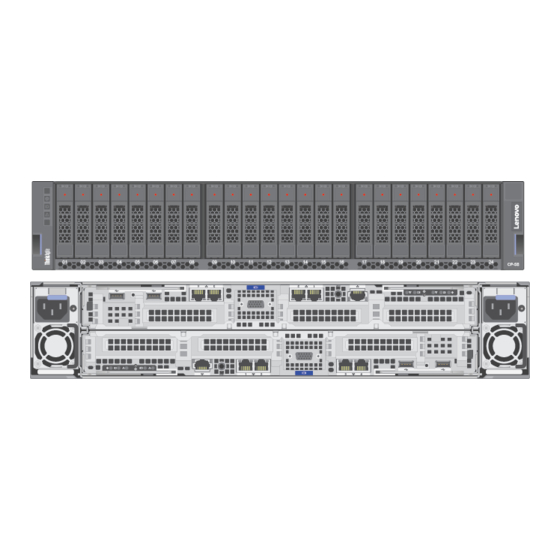
Page 19: Storage Block Components
Figure 5. Storage block components For more information about ordering the parts shown here, see the following website: Lenovo Data Center Support page (7Y66) Chapter 1 ThinkAgile CP Overview... -
Page 20: Compute Block Parts List
Tier 1 CRU at your request with no service agreement, you will be charged for the installation. • Tier 2 customer replaceable unit: You may install a Tier 2 CRU yourself or request Lenovo to install it, at no additional charge, under the warranty service type designated for your compute. -
Page 21: Compute Block Components
Figure 6. Compute block components For more information about ordering the parts shown here, see the following website: Lenovo Data Center Support page (7X20) Chapter 1 ThinkAgile CP Overview... -
Page 22: Power Cords
Information about the power cords available for the ThinkAgile CP storage and compute blocks. Several power cords are available, depending on the country and region where ThinkAgile CP is installed. To view the power cords that are available for a component: •... -
Page 23: Chapter 2. Roles And Responsibilities
• Lenovo Support: Works with solution administrator to perform remote support procedures The following table illustrates which roles are responsible for each of the tasks in this guide. Some tasks can be completed by the customer alone, while other tasks require the participation of Lenovo Support. Actor... -
Page 24: System Board
• Runs command to stop controller remotely via storage controller Support Mode services • Runs command to stop storage controller • (Optional) Enables services Support Mode for ThinkAgile Advantage Support assistance Lenovo ThinkAgile CP Hardware Part Replacement and Component Maintenance Procedures... - Page 25 Actor Task Solution administrator Customer or field service Lenovo Support “Shutting down the storage Powers off the storage block” on page 35 block (all storage controllers) in the Cloud Controller “Replacing storage Physically replaces storage network cables or controller-to-interconnect transceivers” on page 36 cable or transceiver “Remove a hot-swap...
-
Page 26: Rack
“Replacing the Physically replaces management switch management switch in the (optional)” on page 143 rack “Removing the Performs all steps in task management switch (optional)” on page 143 Lenovo ThinkAgile CP Hardware Part Replacement and Component Maintenance Procedures... -
Page 27: Chapter 3. Installation Guidelines
• Make sure the components that you are installing are supported by the solution. • When you install a new solution, apply the latest firmware. This will ensure that any known issues are addressed, and that your solution is ready to work with optimal performance. Contact Lenovo Support for firmware updates. -
Page 28: System Reliability Guidelines
• Remove items from your shirt pocket, such as pens and pencils, in case they fall into the solution as you lean over it. • Avoid dropping any metallic objects, such as paper clips, hairpins, or screws into the solution. Lenovo ThinkAgile CP Hardware Part Replacement and Component Maintenance Procedures... -
Page 29: Handling Static-Sensitive Devices
Handling static-sensitive devices To reduce the possibility of damage from electrostatic discharge, review these guidelines before you handle static-sensitive devices. Attention: Exposure to static electricity may lead to system halt and loss of data. Prevent this problem by keeping static-sensitive components in their static-protective packages until installation, and handling these devices with an electrostatic-discharge wrist strap or other grounding system. - Page 30 Lenovo ThinkAgile CP Hardware Part Replacement and Component Maintenance Procedures...
-
Page 31: Chapter 4. Managing Support Mode
Chapter 4. Managing Support Mode For a Lenovo support agent to access a customer’s ThinkAgile CP environment and provide assistance with its configuration, the customer must enable Support Mode. These topics provide information about the modifications required to ensure that Support Mode in the ThinkAgile CP interconnect switch can be enabled or disabled, as well as accessing the customer’s... -
Page 32: Access The Customer's System Via Support Mode
Step 3. After a few seconds, the interconnect switch port number and password information displays at the top of the Cloud Controller screen. The Lenovo ThinkAgile Advantage Support agent records the port number and password to use in the remote connection. - Page 33 Chapter 4 Managing Support Mode...
-
Page 34: Place A Support File On The Storage Or Compute Node
On the proxy server, create a temporary directory and copy the support file there. Step 3. Log out of the proxy server. Step 4. Use SCP to copy the firmware packages (and LLDP64e) from your laptop to the directory on the proxy server: Lenovo ThinkAgile CP Hardware Part Replacement and Component Maintenance Procedures... - Page 35 Step 5. Establish an SSH session with the proxy server again. Step 6. Make sure that the customer has enabled Support Mode. Step 7. Use scp to copy the files from the SSH proxy to the primary interconnect switch (in the example, the files are copied to a /tmp directory) Note: The port number used to connect to the interconnect switch is provided when the customer enables Support Mode.
-
Page 36: Disable Support Mode In The Cloud Controller
Figure 12. Cloud Controller Support Mode menu item Step 2. A dialog box appears on screen. Click theTurn Off Support Mode button. Figure 13. Turn Off Support Mode dialog box Lenovo ThinkAgile CP Hardware Part Replacement and Component Maintenance Procedures... -
Page 37: Chapter 5. Part Replacement And Maintenance Procedures
Chapter 5. Part replacement and maintenance procedures This section covers the procedures required to maintain and replace ThinkAgile CP hardware components. Storage block maintenance procedures This section covers the procedures required to perform storage block maintenance. Refer to Chapter 2 “Roles and responsibilities” on page 15 to determine who can perform these procedures. -
Page 38: Enclosure Indicators
– Off: the enclosure is not identified • Error/Warning LED indicator: – On: fault conditions are present – Off: the enclosure is operating under normal conditions Figure 14. Enclosure indicators Lenovo ThinkAgile CP Hardware Part Replacement and Component Maintenance Procedures... -
Page 39: Drive Indicators
Drive indicators Storage drives are located in the front of the storage block. Each drive has two LED indicators: • Drive activity LED indicator: – On: drive activity is present – Off: no drive activity • Drive error/warning LED indicator: –... -
Page 40: Storage Controller Indicators
– Constant Off: the controller is operating under normal conditions • Error/Warning LED indicator: – On: fault conditions are present – Off: the controller is operating under normal conditions Figure 16. Storage controller indicators Lenovo ThinkAgile CP Hardware Part Replacement and Component Maintenance Procedures... -
Page 41: Storage Controller Port Indicators
Storage controller port indicators The Ethernet port LED indicators for the storage controllers are found on the rear of the storage block. Each Ethernet port has two LED indicators: • Activity LED indicator: – On: traffic is present on the port –... -
Page 42: Shutting Off A Storage Controller
HA event. To do this, you must simulate storage HA heartbeats between the Storage Controller service running on the active storage controller. Lenovo ThinkAgile CP Hardware Part Replacement and Component Maintenance Procedures... -
Page 43: Shutting Down The Storage Block
> > s s u u d d o o s s y y s s t t e e m m c c t t l l s s t t o o p p t t a a c c p p - - s s t t o o r r a a g g e e - - c c o o n n t t r r o o l l l l e e r r The passive storage controller becomes active in the Cloud Controller. Shutting down the storage block Procedure to power off the ThinkAgile CP storage block. Procedure performed by: Solution administrator Execution: Web Portal only You shut down a storage block (shutting down all storage controllers) directly in the Cloud Controller. -
Page 44: Replacing Storage Block Hardware
Replacing storage block hardware Procedures for replacing the Lenovo ThinkAgile CP storage block hardware. This section provides installation and removal procedures for all serviceable ThinkAgile CP system components. Each component replacement procedure references any tasks that need to be performed to gain access to the component being replaced. - Page 45 $ $ n n v v m m e e l l i i s s t t How do I upgrade the firmware? Contact Lenovo Support to verify the necessary firmware levels or information about updating firmware for the ThinkAgile CP solution.
- Page 46 Do not attempt this option on the enclosure where you are adding or removing disks. Use a new enclosure that is not currently in use. If the disks are part of an existing ThinkAgile CP storage block array, follow these steps to destroy the namespace: 1.
- Page 47 Example of a clean drive configuration This section covers an example of a clean drive configuration. To check the storage drive configuration, use the following command: # # l l s s b b l l k k Following is an example output: NAME MAJ:MIN RM SIZE RO TYPE MOUNTPOINT...
- Page 48 │ └─SPECIAL_TEMPLATE_STORE_cd6d34c281054ef690a89030bef839ec 253:14 0 43.3T 0 dm └─CBS_POOL_meta 253:11 0 16G 0 dm └─CBS_POOL 253:12 0 43.3T 0 dm ├─SPECIAL_METADATA_STORE_4bd8d3ce75b1465082619c1f3fc15fb2 253:13 0 1G 0 dm └─SPECIAL_TEMPLATE_STORE_cd6d34c281054ef690a89030bef839ec 253:14 0 43.3T 0 dm Lenovo ThinkAgile CP Hardware Part Replacement and Component Maintenance Procedures...
- Page 49 nvme6n1 259:11 0 740.4G 0 disk └─sed6 253:6 0 740.4G 0 crypt └─md125 9:125 0 4.3T 0 raid5 └─md124 9:124 0 4.3T 0 raid0 └─vdo_data 253:9 0 4.3T 0 dm └─vdo 253:10 0 43.4T 0 vdo ├─CBS_POOL_data 253:8 0 43.3T 0 dm │└─CBS_POOL 253:12 0 43.3T 0 dm │...
- Page 50 1 root root 7 Aug 20 11:03 /dev/mapper/sed5 -> ../dm-5 lrwxrwxrwx. 1 root root 7 Aug 20 11:03 /dev/mapper/sed6 -> ../dm-6 lrwxrwxrwx. 1 root root 7 Aug 20 11:03 /dev/mapper/sed7 -> ../dm-7 Lenovo ThinkAgile CP Hardware Part Replacement and Component Maintenance Procedures...
- Page 51 Use the following command to list the NVME namespaces: # # l l s s / / d d e e v v / / n n v v m m e e ? ? Following is an example output: /dev/nvme0 /dev/nvme1 /dev/nvme2 /dev/nvme3 /dev/nvme4 /dev/nvme5 /dev/nvme6 /dev/nvme7 To check the drive firmware level, use the following command and check the values in the FW Rev column: $ $ n n v v m m e e l l i i s s t t...
- Page 52 Capacity: 800166076416 bytes 800.166076416 GB Drive Temp: 39 C Drive Health: Ok Total namespaces: 1 Namespace id(s): 1 Namespace 1 size: 794996768768 bytes, 794.996768768 GB Namespace 1 is attached to controller id(s): 33 Lenovo ThinkAgile CP Hardware Part Replacement and Component Maintenance Procedures...
- Page 53 NVMe control device: /dev/nvme6 Slot: 2 Manufacturer: SAMSUNG MZWLL800HEHP-00003 Serial number: S3HCNX0JC02188 Firmware: GPNA9B3Q Capacity: 800166076416 bytes 800.166076416 GB Drive Temp: 39 C Drive Health: Ok Total namespaces: 1 Namespace id(s): 1 Namespace 1 size: 794996768768 bytes, 794.996768768 GB Namespace 1 is attached to controller id(s): 33 NVMe control device: /dev/nvme7 Slot: 1 Manufacturer: SAMSUNG MZWLL800HEHP-00003...
- Page 54 Active Devices : 6 Working Devices : 7 Failed Devices : 1 Spare Devices : 1 Layout : left-symmetric Chunk Size : 16K Consistency Policy : bitmap Rebuild Status : 20% complete Lenovo ThinkAgile CP Hardware Part Replacement and Component Maintenance Procedures...
- Page 55 Name : any:md5 UUID : 5f7b873c:16d6d418:7b5f6fde:247566a7 Events : 162 Number Major Minor RaidDevice State active sync /dev/dm-0 active sync /dev/dm-1 active sync /dev/dm-2 spare rebuilding /dev/dm-7 active sync /dev/dm-4 active sync /dev/dm-5 active sync /dev/dm-6 faulty /dev/dm-3 In this example, dm-3 is marked as failed (dm-3[3](F)). To remove a drive from the RAID array, follow these steps: Determine the SED mapping for dm-3: Step 1.
- Page 56 Capacity: 800166076416 bytes 800.166076416 GB Drive Temp: 40 C Drive Health: Ok Total namespaces: 1 Namespace id(s): 1 Namespace 1 size: 794996768768 bytes, 794.996768768 GB Namespace 1 is attached to controller id(s): 33 Lenovo ThinkAgile CP Hardware Part Replacement and Component Maintenance Procedures...
- Page 57 NVMe control device: /dev/nvme4 Slot: 4 Manufacturer: SAMSUNG MZWLL800HEHP-00003 Serial number: S3HCNX0JC02189 Firmware: GPNA9B3Q Capacity: 800166076416 bytes 800.166076416 GB Drive Temp: 40 C Drive Health: Ok Total namespaces: 1 Namespace id(s): 1 Namespace 1 size: 794996768768 bytes, 794.996768768 GB Namespace 1 is attached to controller id(s): 33 NVMe control device: /dev/nvme5 Slot: 3 Manufacturer: SAMSUNG MZWLL800HEHP-00003...
- Page 58 State : clean, degraded, recovering Active Devices : 6 Working Devices : 7 Failed Devices : 0 Spare Devices : 1 Layout : left-symmetric Chunk Size : 16K Consistency Policy : bitmap Lenovo ThinkAgile CP Hardware Part Replacement and Component Maintenance Procedures...
- Page 59 Rebuild Status : 62% complete Name : any:md5 UUID : 5f7b873c:16d6d418:7b5f6fde:247566a7 Events : 480 Number Major Minor RaidDevice State active sync /dev/dm-0 active sync /dev/dm-1 active sync /dev/dm-2 spare rebuilding /dev/dm-7 active sync /dev/dm-4 active sync /dev/dm-5 active sync /dev/dm-6 Step 5.
-
Page 60: Hot-Swap Drive Removal
Procedure performed by: customer or field service To remove a hot-swap drive, complete the following steps: Step 1. To open the drive tray handle, press the tab. Figure 18. Hot-swap drive removal Lenovo ThinkAgile CP Hardware Part Replacement and Component Maintenance Procedures... -
Page 61: Hot-Swap Drive Removal
Step 2. Grasp the handle and slide the drive out of the drive bay. Figure 19. Hot-swap drive removal Step 3. Check the status of the RAID array to verify that slot 5 is empty: # # / / u u s s r r / / s s h h a a r r e e / / t t a a c c p p / / l l e e n n o o v v o o / / t t a a c c p p - - n n v v m m e e - - c c o o n n t t r r o o l l . . p p y y - - d d i i s s p p l l a a y y Following is an example output: discovering NVMe disks. - Page 62 Capacity: 800166076416 bytes 800.166076416 GB Drive Temp: 40 C Drive Health: Ok Total namespaces: 1 Namespace id(s): 1 Namespace 1 size: 794996768768 bytes, 794.996768768 GB Namespace 1 is attached to controller id(s): 33 Lenovo ThinkAgile CP Hardware Part Replacement and Component Maintenance Procedures...
-
Page 63: Namespace 1 Size: 794996768768 Bytes, 794.996768768 Gb
NVMe control device: /dev/nvme6 Slot: 1 Manufacturer: SAMSUNG MZWLL800HEHP-00003 Serial number: S3HCNX0JC02188 Firmware: GPNA9B3Q Capacity: 800166076416 bytes 800.166076416 GB Drive Temp: 40 C Drive Health: Ok Total namespaces: 1 Namespace id(s): 1 Namespace 1 size: 794996768768 bytes, 794.996768768 GB Namespace 1 is attached to controller id(s): 33 NVMe control device: /dev/nvme7 Slot: 2 Manufacturer: SAMSUNG MZWLL800HEHP-00003... -
Page 64: Opening The Drive Tray Handle
To install a hot-swap drive, complete the following steps: Step 1. To open the drive tray handle, press the release tab. Figure 20. Opening the drive tray handle Lenovo ThinkAgile CP Hardware Part Replacement and Component Maintenance Procedures... -
Page 65: Sliding The Drive Into The Drive Bay
Step 2. Slide the drive into the drive bay until it snaps into position. Figure 21. Sliding the drive into the drive bay Step 3. Close the drive tray handle to lock the drive in place. Step 4. Check the drive status LED to verify that the drive is operating correctly. •... -
Page 66: Namespace 1 Is Attached To Controller Id(S): 33
Namespace 1 is attached to controller id(s): 33 NVMe control device: /dev/nvme3 Slot: 5 Manufacturer: SAMSUNG MZWLL1T6HEHP-00003 Serial number: S3HDNX0JB00078 Firmware: GPNA9B3Q Capacity: 1600321314816 bytes 1600.32131482 GB Drive Temp: 39 C Drive Health: Ok Total namespaces: 0 Lenovo ThinkAgile CP Hardware Part Replacement and Component Maintenance Procedures... -
Page 67: Nvme Control Device: /Dev/Nvme7
NVMe control device: /dev/nvme4 Slot: 4 Manufacturer: SAMSUNG MZWLL800HEHP-00003 Serial number: S3HCNX0JC02189 Firmware: GPNA9B3Q Capacity: 800166076416 bytes 800.166076416 GB Drive Temp: 40 C Drive Health: Ok Total namespaces: 1 Namespace id(s): 1 Namespace 1 size: 794996768768 bytes, 794.996768768 GB Namespace 1 is attached to controller id(s): 33 NVMe control device: /dev/nvme5 Slot: 3 Manufacturer: SAMSUNG MZWLL800HEHP-00003... - Page 68 0/6 pages [0KB], 65536KB chunk md126 : active raid1 sda[1] sdb[0] 118778880 blocks super external:/md127/0 [2/2] [UU] md127 : inactive sda[1](S) sdb[0](S) 6306 blocks super external:imsm unused devices: <none> Lenovo ThinkAgile CP Hardware Part Replacement and Component Maintenance Procedures...
- Page 69 To view detailed information about the status of the RAID array, use the following command: # # m m d d a a d d m m - - - - d d e e t t a a i i l l / / d d e e v v / / m m d d / / m m d d 5 5 Following is an example output: /dev/md/md5: Version : 1.2...
-
Page 70: Hot-Swap Power Supply Replacement
The device also might have more than one power cord. To remove all electrical current from the device, ensure that all power cords are disconnected from the power source. Lenovo ThinkAgile CP Hardware Part Replacement and Component Maintenance Procedures... - Page 71 S001 DANGER Electrical current from power, telephone, and communication cables is hazardous. To avoid a shock hazard: • Do not connect or disconnect any cables or perform installation, maintenance, or reconfiguration of this product during an electrical storm. • Connect all power cords to a properly wired and grounded electrical outlet. •...
-
Page 72: Hot-Swap Power Supply Removal
To remove a hot-swap power supply, complete the following steps: Step 1. Disconnect the power cord from the hot-swap power supply. Step 2. Open the handle. Figure 22. Hot-swap power supply removal (1/2) Lenovo ThinkAgile CP Hardware Part Replacement and Component Maintenance Procedures... -
Page 73: Hot-Swap Power Supply Removal
Step 3. Press the release tab down, and pull the handle at the same time to slide the hot-swap power supply out of the enclosure. Figure 23. Hot-swap power supply removal (2/2) The removal of the hot-swap power supply is now complete. After removing the hot-swap drive: •... - Page 74 The device also might have more than one power cord. To remove all electrical current from the device, ensure that all power cords are disconnected from the power source. Lenovo ThinkAgile CP Hardware Part Replacement and Component Maintenance Procedures...
- Page 75 S001 DANGER Electrical current from power, telephone, and communication cables is hazardous. To avoid a shock hazard: • Do not connect or disconnect any cables or perform installation, maintenance, or reconfiguration of this product during an electrical storm. • Connect all power cords to a properly wired and grounded electrical outlet. •...
-
Page 76: Hot-Swap Power Supply Installation
Press the release tab down, and slide the new hot-swap power supply into the bay at the same time until the release latch clicks into place. Figure 24. Hot-swap power supply installation (1/2) Lenovo ThinkAgile CP Hardware Part Replacement and Component Maintenance Procedures... -
Page 77: Hot-Swap Power Supply Installation
Step 3. Close the handle. Figure 25. Hot-swap power supply installation (2/2) The installation of a hot-swap power supply is now complete. After installing the power supply: • Connect one end of the power cord to the new power supply connector. Then, connect the other end of the power cord into a properly grounded electrical outlet. -
Page 78: Hot-Swap Storage Controller Replacement
Remove a hot-swap storage controller This procedure describes how to remove a storage controller from a ThinkAgile CP configuration. Procedure performed by: customer or field service... -
Page 79: Hot-Swap Storage Controller Installation
Install a hot-swap storage controller This procedure explains how to add a storage controller to the ThinkAgile CP configuration, assuming a storage controller has been previously removed. Procedure performed by: customer or field service... - Page 80 Lenovo ThinkAgile CP Hardware Part Replacement and Component Maintenance Procedures...
- Page 81 Notes: • The electromagnetic interference (EMI) integrity and cooling of the storage are protected by having all bays covered or occupied. When replacing a storage controller, minimize the amount of time of the empty bay to avoid overheating or abnormal operation. •...
- Page 82 Update the storage node VPD This section covers the procedure to update the ThinkAgile CP storage node VPD. Prior to updating the storage node VPD, perform the following tasks: • “Enable Support Mode in the Cloud Controller” on page 23 •...
-
Page 83: Ssh Sign-In To Proxy Server
ESM A (bottom controller) and then hard-reboot ESM B. Access the storage controller using Support Mode This section covers the procedure to access the storage controller using Support Mode. Performed By: Lenovo Support To access the storage controller using Support Mode, follow these steps: Step 1. -
Page 84: Entering The Proxy Server Port
Figure 29. Entering the proxy server port Enter yes at the prompt. The password is located next to the port number in Cloud Controller. Figure 30. Entering the proxy server password Lenovo ThinkAgile CP Hardware Part Replacement and Component Maintenance Procedures... - Page 85 Obtain storage controller IP addresses This section covers the procedure to obtain the storage controller IP addresses. To obtain the storage controller IP addresses, follow these steps: Step 1. To obtain the storage controller IP addresses from the Cloud Controller: Navigate to the Organization Viewer topic.
-
Page 86: Enclosure Replacement
Step 2. Remove both side covers on the enclosure by grasping and pulling out the bottom of the side cover, and then pulling it straight up. Figure 31. Side cover removal Lenovo ThinkAgile CP Hardware Part Replacement and Component Maintenance Procedures... -
Page 87: Screws Removal
Step 3. Remove the M5 screws and thumbscrews on both sides used to fasten the storage enclosure. Keep the M5 screws for installing the new enclosure. Figure 32. Screws removal Step 4. Slide the storage enclosure out of the rack along the rails and put it in a safe, static-protective place. - Page 88 • Install a new enclosure. See “Install the enclosure” on page 81. • If you are instructed to return the component or optional device, follow all packaging instructions, and use any packaging materials for shipping that are supplied to you. Lenovo ThinkAgile CP Hardware Part Replacement and Component Maintenance Procedures...
-
Page 89: Removal Of Side Cover
• “Hot-swap power supply” on page 66 • “Storage controllers” on page 71 To install the ThinkAgile CP storage enclosure on the slide rails, do the following: Step 2. Remove both of the side covers on the enclosure by grasping and pulling out the bottom of each side cover, and then pulling it straight up. -
Page 90: Installing The Enclosure Into The Rack
Figure 35. Installing the enclosure into the rack Step 5. Secure the enclosure with the thumbscrews and the M5 screws on the front. Figure 36. Installing screws on front of enclosure Lenovo ThinkAgile CP Hardware Part Replacement and Component Maintenance Procedures... -
Page 91: Reinstalling The Side Cover
Step 6. On each side of the storage enclosure, fit the hook on the top of the side cover and push the bottom of it inward to reinstall the side cover to the storage enclosure. Figure 37. Reinstalling the side cover Step 7. -
Page 92: Complete The Parts Replacement
Attention: To avoid component damage, connect the power cords last. Step 4. Update the storage configuration if necessary. Download and install the latest device drivers: https://datacentersupport.lenovo.com/products/ solutions-and-software/thinkagile-cp/ Update the system firmware. Lenovo ThinkAgile CP Hardware Part Replacement and Component Maintenance Procedures... -
Page 93: Compute Block Maintenance Procedures
Compute block maintenance procedures This section covers the procedures required to perform compute block maintenance. Refer to Chapter 2 “Roles and responsibilities” on page 15 to determine who can perform these procedures. Shutting off a compute node This procedure describes how to shut off a compute node and how to handle the VMs running on the compute node. -
Page 94: Migrate A Vm Between Compute Nodes
Step 4. Remove the tag from the migrated VM. Important: This removal must be done before proceeding to the next step. Step 5. Remove the tag from the compute node. Lenovo ThinkAgile CP Hardware Part Replacement and Component Maintenance Procedures... -
Page 95: Replacing Compute Block Hardware
CRU, but you will be charged for the service. • Field-replaceable unit (FRU): You may install a FRU yourself, or request a Lenovo to install it at no additional charge while the appliance is under warranty. -
Page 96: Enable Or Disable Maintenance Mode
Navigate to the Compute Block section. Step 4. Click the button next to the desired node and select Turn on maintenance mode..Figure 38. Enable Maintenance Mode for a Node Lenovo ThinkAgile CP Hardware Part Replacement and Component Maintenance Procedures... -
Page 97: Maintenance Mode Dialog Box
Step 5. If there are any application instances currently running on the compute node, you must select an action for each instance from the Action Plan drop-down menu and then click Continue: • Migrate • Remove constraints and migrate • Shut down •... -
Page 98: Disable Maintenance Mode For A Node
Click the button next to the desired node and select Turn off maintenance mode..Figure 40. Disable Maintenance Mode for a Node Maintenance Mode for the compute node is now disabled. Lenovo ThinkAgile CP Hardware Part Replacement and Component Maintenance Procedures... -
Page 99: Hot-Swap Drive Replacement
Hot-swap drive replacement Follow these instructions to replace a front SSD in the ThinkAgile CP compute block appliance. Each ThinkAgile CP compute block appliance supports Intel 240GB solid-state drives (SSDs). These drives are used for installing the operating system and no user data are stored on these drives. These drives are used in RAID 1 mode. -
Page 100: Drive Removal
The following notes describe the drive that the node supports, and other information that you must consider when you install a drive. • Supported drive: ThinkSystem 2.5" Intel S4500 240GB Entry SATA 6GB Hot-swap SSD. Lenovo ThinkAgile CP Hardware Part Replacement and Component Maintenance Procedures... -
Page 101: Drive Installation
• Locate the documentation that comes with the drive and follow those instructions in addition to the instructions in this chapter. • You can install up to two hot-swap SATA 2.5-inch drives for each node. • The electromagnetic interference (EMI) integrity and cooling of the solution are protected by having all bays and PCI and PCI Express slots covered or occupied. -
Page 102: Hot-Swap Power Supply Replacement
2. First, remove power cords from outlet. 3. Attach signal cables to connectors. 3. Remove signal cables from connectors. 4. Attach power cords to outlet. 4. Remove all cables from devices. 5. Turn device ON. Lenovo ThinkAgile CP Hardware Part Replacement and Component Maintenance Procedures... - Page 103 1. Disconnect the power cords and all external cables. 2. Identify the failed power supply. ThinkAgile CP Compute Block appliances contain two power supplies. Note: If the amber warning LED on the node front panel is illuminated, then a power supply unit has failed.
-
Page 104: Hot-Swap Power Supply Removal
• Install a new power supply unit. See “Install a hot-swap power supply” on page 97 • If you are instructed to return the component or optional device, follow all packaging instructions, and use any packaging materials for shipping that are supplied to you. Lenovo ThinkAgile CP Hardware Part Replacement and Component Maintenance Procedures... - Page 105 Install a hot-swap power supply Use this information to install a hot-swap power supply. Chapter 3 “Read “ATTENTION: Static Sensitive Device Installation Ground package before Guidelines” on opening” on page 21 page 19 To avoid possible danger, read and follow the following safety statement. S001 DANGER Electrical current from power, telephone, and communication cables is hazardous.
- Page 106 • Check the rear of the node to ensure that there is no length difference between the two installed units. A visible difference in length means that the two units have different wattages, and one of them must be replaced. Lenovo ThinkAgile CP Hardware Part Replacement and Component Maintenance Procedures...
-
Page 107: Fan Replacement
Procedure performed by: customer or field service Complete the following steps to install a hot-swap power supply. Step 1. Slide the hot-swap power supply into the bay until the release latch clicks into place. Important: During normal operation, each power-supply bay must contain either a power supply or power-supply filler panel for proper cooling. - Page 108 Hazardous moving fan blades nearby. S033 CAUTION: Hazardous energy present. Voltages with hazardous energy might cause heating when shorted with metal, which might result in spattered metal, burns, or both. Lenovo ThinkAgile CP Hardware Part Replacement and Component Maintenance Procedures...
-
Page 109: Fan Fault Leds
Before removing a fan: 1. Remove the fan cover (see http://thinksystem.lenovofiles.com/help/topic/7X21/remove_the_fan_cover.html Attention: • Static electricity released into internal solution components when the solution is powered on may cause the solution to halt, which may result in data loss. To avoid this problem, always use an electrostatic-discharge wrist strap or other grounding system when you work inside the solution with the power on. - Page 110 • Install a new fan. See “Install a fan” on page 104 • If you are instructed to return the component or optional device, follow all packaging instructions, and use any packaging materials for shipping that are supplied to you. Lenovo ThinkAgile CP Hardware Part Replacement and Component Maintenance Procedures...
- Page 111 Remove a 80x80x80 mm Fan Procedure for removing a 80x80x80 mm fan from the compute enclosure. Procedure performed by: customer or field service Complete the following steps to remove a fan: To remove a 80x80x80 mm fan, follow these steps: Step 1.
- Page 112 • Replace the failed fan and reinstall the fan cover in three minutes. Lenovo ThinkAgile CP Hardware Part Replacement and Component Maintenance Procedures...
- Page 113 Install a 60x60x56 mm Fan Use this information to install a 60x60x56 mm fan in the compute enclosure. Procedure performed by: customer or field service Complete the following steps to install a fan. To install a 60x60x56mm fan, follow these steps: Step 1.
- Page 114 • The amber warning LED on the node front panel is off. 3. If you are instructed to return the component or optional device, follow all packaging instructions, and use any packaging materials for shipping that are supplied to you. Lenovo ThinkAgile CP Hardware Part Replacement and Component Maintenance Procedures...
-
Page 115: Eiom Replacement
Use the following procedures to remove and install the Ethernet I/O module (EIOM). The ThinkAgile CP Compute Block appliances offer connectivity to the LOM (LAN on motherboard) of each node via ports on the EIOM located at the rear of the enclosure. The top Phy maps to port one of the system LOM, the bottom Phy maps to port two of the system LOM. -
Page 116: Eiom Removal
Then, take the new EIOM out of the package and place it on a static-protective surface. Note: The minimum networking speed requirement for the EIOM is 1Gbps. Lenovo ThinkAgile CP Hardware Part Replacement and Component Maintenance Procedures... -
Page 117: Eiom Installation
Procedure performed by: customer or field service Complete the following steps to install the 10GbE cage (SFP+) model EIOM. Step 1. Grasp the EIOM and align the four EIOM tabs with the slots in the shuttle. Then, lower the EIOM into the slots, and then pull the EIOM slightly towards the rear side of the shuttle. -
Page 118: Dimm Replacement
3. Power off the node and if the cable management arm is not in place, disconnect all the cables. 4. Remove the compute node from the enclosure (see http://thinksystem.lenovofiles.com/help/topic/7X21/ remove_a_compute_node_from_the_chassis.html 5. Remove the compute node cover (see http://thinksystem.lenovofiles.com/help/topic/7X21/remove_the_ compute_node_cover.html 6. Remove the air baffle (see http://thinksystem.lenovofiles.com/help/topic/7X21/remove_the_air_baffle.html Lenovo ThinkAgile CP Hardware Part Replacement and Component Maintenance Procedures... -
Page 119: Dimm Removal
Procedure performed by: Customer or field service Complete the following steps to remove a DIMM: Step 1. Carefully press down the retaining clips on each end of the DIMM connector. Attention: To avoid breaking the retaining clips or damaging the DIMM connectors, open and close the clips gently. - Page 120 – 2 = 2 logical ranks in each package rank – 4 = 4 logical ranks in each package rank – 8 = 8 logical ranks in each package rank Lenovo ThinkAgile CP Hardware Part Replacement and Component Maintenance Procedures...
-
Page 121: Location Of The Dimm Connectors On The
– R = rank(s) – xff = Device organization (data bit width) of SDRAMs used on this assembly • x4 = x4 organization (4 DQ lines per SDRAM) • x8 = x8 organization • x16 = x16 organization – wwwww is the DIMM bandwidth, in MBps: 2133, 2400, 2666, 2933, 3200 –... -
Page 122: Dimm Installation Sequence (Independent Mode/Normal Mode)
6, 14, 3, 11, 7, 15, 2, 10, 8, 16, 1, 9, 5, 13, 4, 12 Note: Single-rank RDIMM is not supported by sparing. If you install single-rank RDIMM, it switches to the independent mode automatically. Lenovo ThinkAgile CP Hardware Part Replacement and Component Maintenance Procedures... -
Page 123: Location Of The Dimm Connectors On The
Install DIMM Use this information to install a DIMM. Chapter 3 “Read “ATTENTION: “Power off the compute Static Sensitive Device Installation Ground package before node” on page Guidelines” on opening” on page 21 page 19 Attention: Memory modules are sensitive to static discharge and require special handling. In addition to the standard guidelines for “Handling static-sensitive devices”... -
Page 124: Dimm Installation
Note: If there is a gap between the DIMM and the retaining clips, the DIMM has not been correctly inserted; open the retaining clips, remove the DIMM, and then reinsert it. Step 6. Reconnect any cable that you removed. Lenovo ThinkAgile CP Hardware Part Replacement and Component Maintenance Procedures... - Page 125 The installation of the DIMM is now complete. After you install a DIMM, complete the following steps: 1. Reinstall the air baffle (see http://thinksystem.lenovofiles.com/help/topic/7X21/install_the_air_baffle.html 2. Reinstall the compute node cover (see http://thinksystem.lenovofiles.com/help/topic/7X21/install_the_ compute_node_cover.html 3. Reinstall the compute node (see http://thinksystem.lenovofiles.com/help/topic/7X21/install_a_compute_ node_in_the_chassis.html 4.
-
Page 126: Compute Node Replacement
Use the following procedures to remove and install the compute node from the ThinkSystem D2 Enclosure. Remove a compute node This procedure describes how to remove a compute node from your ThinkAgile CP configuration. Procedure performed by: Solution administrator, ThinkAgile Advantage Support To remove a compute node from your ThinkAgile CP configuration, perform the following steps: Step 1. - Page 127 Step 8. (Optional) In the Compute Tags field, specify compute tags. Compute tags are additional information that can be applied to nodes. While each node must belong to exactly one category, a node may have any number of tags. The Cloud Controller uses tags to match application resource constraints and available nodes.
-
Page 128: Replace The Sd530 System Board
Follow this procedure to replace the SD530 system board. Procedure performed by: Solution administrator To replace the SD530 system board from the ThinkAgile CP, perform these steps. Step 1. Get the serial number and (optional) UUID information from Lenovo Cloud Controller. -
Page 129: Interconnect Switch Maintenance Procedures
The interconnect switch can now be unplugged safely. Make the secondary interconnect switch the primary interconnect Procedure for making the secondary ThinkAgile CP interconnect switch into the primary interconnect. Attention: You have between 6 and 12 hours to fix the primary interconnect before you notice network connectivity problems, as that is the default lease time of the DHCP server. - Page 130 Important: This procedure can be performed only under supervision of or with help from Lenovo Support. Execution: On hardware only Performed by: Lenovo Support Background: Dual interconnect configuration (DS-V3) is active-active.
-
Page 131: Recabling Management Switch From Primary
address 100.64.253.1; port 647; peer address 100.64.253.2; peer port 647; max-response-delay 60; max-unacked-updates 10; auto-partner-down 1; mclt 120; split 255; load balance max seconds 3; Step 5. Disconnect the hardware management network cable from the former primary interconnect and connect it to the current primary (former secondary) interconnect. Figure 57. -
Page 132: Recovering From Dns Misconfiguration
If this happens, do not attempt to rerun the script v3/tacp_switch_config_v3. Important: This procedure can be performed only by Lenovo Professional Services. To recover from DNS misconfiguration, follow these steps: Update /etc/tacp/tacp_switch_resource.sh with the correct DNS IP address on both interconnect Step 1. - Page 133 Step 4. Restart the DHCP server on the primary interconnect switch: > > s s u u d d o o s s e e r r v v i i c c e e i i s s c c - - d d h h c c p p - - s s e e r r v v e e r r s s t t o o p p >...
-
Page 134: Interconnect Parts Replacement Procedures
Procedures for replacing the Lenovo ThinkAgile CP interconnect. To replace an interconnect switch, first remove the unit from the rack and then install the new interconnect switch as described in the following sections. Lenovo ThinkAgile CP Hardware Part Replacement and Component Maintenance Procedures... -
Page 135: Removing The Interconnect From The
Step 5. Remove the four screws (3) on the front- and rear-post brackets. Figure 58. Removing the interconnect from the rack Replace the interconnect switch by following the steps in “Install the ThinkAgile CP interconnect switch” on page 128. Chapter 5... - Page 136 • The switch drawings in this topic are for illustration only and may not match your specific switch model. • If you are using a non-Lenovo switch as the management switch, keep 1U of empty space between the interconnect switches and the management switch so that power or network cables can use this space.
- Page 137 Step 2. Attach the brackets. CAUTION: Installing the switch in a rack requires two people. One person should position the interconnect switch in the rack, while the other secures it using the rack screws. Attach each of the rails to the interconnect switch using four of the included rail screws. Use an additional two screws to secure each of the rails at the midpoint on the sides of the interconnect switch.
- Page 138 Install one or two AC power modules in the switch. The switch supports up to two PSUs that must have the same matching airflow direction as the installed fan tray. Connect an external AC power source to the modules. Lenovo ThinkAgile CP Hardware Part Replacement and Component Maintenance Procedures...
- Page 139 Step 6. Verify basic switch operation by checking the system LEDs. When operating normally, the PSU1/ PSU2, Diag, and Fan LEDs should all be green. Step 7. Connect the network cables. For the RJ-45 Management port, connect 100-ohm Category 5, 5e or better twisted-pair cable. Connect DAC cables to the SFP+/QSFP+ slots.
- Page 140 View the product label. The switch product label is located below SFP+ ports 7–12 on left side of the front panel. Pull the label out to view the product information. The installation of the interconnect switch is now complete. Lenovo ThinkAgile CP Hardware Part Replacement and Component Maintenance Procedures...
- Page 141 • the reserved VLAN IDs (Hardware management network, MLAG/ISL, Hypervisor, Uplink) • the peerServiceTag of the primary interconnect Procedure performed by: customer or field service, Lenovo Support Step 1. Configure the interconnect you are replacing outside of the stack environment.
-
Page 142: Cabling A Single-Interconnect Configuration
• Lower storage block port (S.L.M.) using a RJ45 patch cable Figure 59. Hardware management network connectivity in a single interconnect configuration Note: If not using the Lenovo ThinkSystem NE0152T RackSwitch as the management switch, you may require different cables for the management network connections. - Page 143 Compute block connections (single-interconnect configuration) The compute block consists of an enclosure with up to four compute nodes, which are numbered as follows: Connect the compute nodes according to the populated compute node location and corresponding port mapping. The cables to be used are clearly labeled; make sure that you use the correct cables. You need two SFP+ Direct Attach Cables (DACs) for each populated compute node.
-
Page 144: Single-Interconnect Configuration - Compute Node And Network Interconnect Connections
Figure 60. Single—interconnect configuration — compute node and network interconnect connections Lenovo ThinkAgile CP Hardware Part Replacement and Component Maintenance Procedures... -
Page 145: Single-Interconnect Configuration - Storage Block And Network Interconnect Connections
Storage block connections (single-interconnect configuration) Connect the storage controllers according to the populated controller location and corresponding port mapping. The cables to be used are clearly labeled; make sure that you use the correct cables. You need eight Category 6 patch cables and eight SFP+ transceivers. Attach a single SFP+ transceiver to each patch cable. -
Page 146: Cabling A Dual-Interconnect Configuration
• Lower storage block port (S.L.M.) using a RJ45 patch cable Figure 62. Hardware management network connectivity in a dual—interconnect configuration Note: If not using the Lenovo ThinkSystem NE0152T RackSwitch as the management switch, you may require different cables for the management network connections. - Page 147 Compute block connections (dual-interconnect configurations) The compute block consists of an enclosure with up to four compute nodes, which are numbered as follows: Connect the compute nodes according to the populated compute node location and the corresponding port mapping. The cables to be used are clearly labeled; make sure that you use the correct cables. You need two SFP+ Direct Attach Cables (DACs) for each populated compute node.
-
Page 148: Dual-Interconnect Configuration - Compute Node And Network Interconnect Connections
Lower storage controller, port 1 (S. Primary interconnect, port 21 L.1) Lower storage controller, port 2 (S. Primary interconnect, port 24 L.2) Lower storage controller, port 3 (S. Secondary interconnect, port 21 L.3) Lenovo ThinkAgile CP Hardware Part Replacement and Component Maintenance Procedures... -
Page 149: Dual-Interconnect Configuration - Storage Block And Network Interconnect Connections
Front storage controller location Back network port mapping Network interconnect port Lower storage controller, port 4 (S. Secondary interconnect, port 24 L.4) Figure 64. Dual—interconnect configuration — storage block and network interconnect connections Peer-link connection (dual-interconnect configuration) Set up the peer link between the interconnects using the QSFP+ Direct Attach Cables (DACs) that are provided with the configuration. -
Page 150: Replacing A Cable Between Two Interconnect Switches
DHCP renewal. This operation can be done live without any specific pre- or post-steps. During this operation, the hardware management network, the storage HA feature, and hardware detection functionality are unavailable. Hardware-related statistics also cannot be retrieved. Lenovo ThinkAgile CP Hardware Part Replacement and Component Maintenance Procedures... -
Page 151: Management Switch Maintenance Procedures (Optional)
Management switch maintenance procedures (optional) Procedures for replacing the Lenovo ThinkAgile CP management switch. Note: A dedicated out-of-band management switch is required for this solution. If the Lenovo ThinkSystem NE0152T RackSwitch is not used, you must provide an out-of-band management switch with the correct configuration. -
Page 152: Power-Cord Retention Clip Removal
To replace the NE0152T from a standard rack, complete the following steps: Step 1. If the power cord retention clip is installed, remove it: Figure 66. Power-cord retention clip removal Lenovo ThinkAgile CP Hardware Part Replacement and Component Maintenance Procedures... -
Page 153: Releasing Switch Unit From The Rack
Step 2. Disconnect all external cables. Step 3. Loosen and remove M6 screws, washers, and clip nuts (or cage nuts) to release the switch unit from the rack. Figure 67. Releasing switch unit from the rack Step 4. Slide the switch unit out of the rack. Step 5. -
Page 154: Item
• For earthquake stability, mount the switch in a 4-post rack. • If you are using a non-Lenovo switch as the management switch, keep 1U of empty space between the interconnect switches and the management switch so that power or network cables can use this space. -
Page 155: Attaching Mounting Brackets To Switch
To install the ThinkSystem NE0152T RackSwitch in a standard equipment rack, complete the following steps: Step 1. Locate, record, and retain the product switch information in order to configure and register your product. Step 2. Attach a mounting bracket (item 1 in the illustration) to each side of the switch with M4 screws (item 2). -
Page 156: Installing Power Cord Retention Clip
Note: The power cord retention clip is not used when the 1U air‐duct option is installed. Figure 71. Installing power cord retention clip The installation of the management switch is now complete. Lenovo ThinkAgile CP Hardware Part Replacement and Component Maintenance Procedures... -
Page 157: Hardware Management Network Cable Replacement
Hardware management network cable replacement This section describes how to replace a hardware management network cable. Procedure performed by: Customer or field service When replacing cables that connect any Baseboard Management Controller (BMC) from the compute enclosure, storage controllers, or the primary interconnect-dedicated port to the management switch, you are required to unplug all hardware management network cables and then plug back into the management switch to initiate a DHCP renewal. - Page 158 Lenovo ThinkAgile CP Hardware Part Replacement and Component Maintenance Procedures...
-
Page 159: Chapter 6. Licensing Considerations
Chapter 6. Licensing considerations The following table explains the details of the ThinkAgile CP Guardian edition. Guardian Operating System (for compute nodes and storage RHEL 7 controllers) Network Operating System for Interconnect Switches Pica8 OS ✓ At-Rest Encryption Compliance ✓... - Page 160 Lenovo ThinkAgile CP Hardware Part Replacement and Component Maintenance Procedures...