Table of Contents
Advertisement
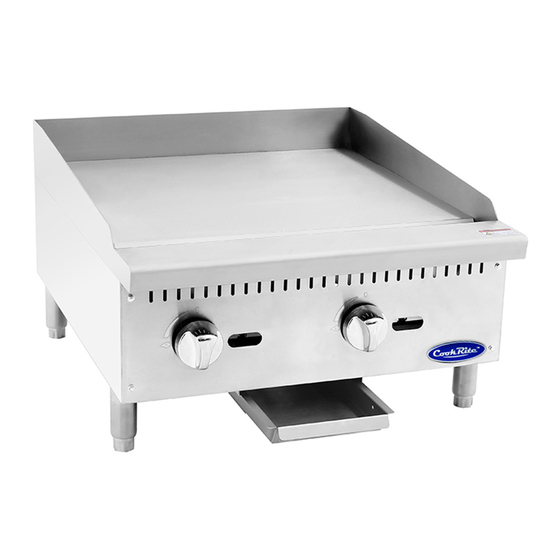
Gas Countertop Griddles
Operating Instructions
Before you begin, please read these instructions carefully to
usethisproductcorrectly,tomaketheproductperformideally,and to avoid
hazards.
Models:ATMG-24 / ATMG-36 / ATMG-48
Dear customers and users:
Thankyou for purchasing our products. In order to be able to better use
thisproduct,pleasereadtheseinstructionscarefullybeforeanyoperation,
and follow the guide, to avoid any unnecessary trouble during using.
Advertisement
Table of Contents

Summary of Contents for CookRite ATMG-24
- Page 1 Operating Instructions Before you begin, please read these instructions carefully to usethisproductcorrectly,tomaketheproductperformideally,and to avoid hazards. Models:ATMG-24 / ATMG-36 / ATMG-48 Dear customers and users: Thankyou for purchasing our products. In order to be able to better use thisproduct,pleasereadtheseinstructionscarefullybeforeanyoperation, and follow the guide, to avoid any unnecessary trouble during using.
- Page 2 Please keep this instruction manual in a safe place for convenient reference and operation. Thisinstructionmanualissubjecttoanychangewithoutfurthernotice, and the manufacturer reserves the right of final interpretation. The appliance is designed for commercial purposes, not for household use. A statement instructing the purchaser to post in a prominent location instructions to be followed in the event the user smells gas.
-
Page 3: Table Of Contents
4.Parameter Specifications……………………………………………4 5.Transport and Storage ………………………………………………5 6.Installation and Debugging…………………………………………6 7.Safety Notices and Precautions……………………………………8 8.Operating Instructions………………………………………………9 9.CleaningandMaintenance……………………………………………11 10. Troubleshooting ……………………………………………………12 11.SpareParts……………………………………………………………13 12. Accessories List……………………………………………………17 1. Safety Protection Pleasemakesure thatthe operator isanauthorizedandlicensed technician before you allow him/her to install and operate the products. Be sure to strictly follow this instruction guide during installation and using. -
Page 4: Parameter Specifications
Be repaired or changed by unauthorized technicians; Use the spare parts or accessories provided by non-manufacturers; Accidents caused by force majeure; Not strictly comply with related guide of instruction by any reason. 4. Parameter Specifications 4.1、Outline Dimensions(in) ATMG-24 - 3 -... - Page 5 - 4 -...
-
Page 6: Transport And Storage
4.2、Information of Gas Supply and Burner The minimum supplied gas pressure regulator is factory set at 4”Natural Gas W.C, and 10”L.P. Gas W.C. The external thread of product’s intake-tube is 3/4 inches. <Table 1> Intake-tube #of burners Per BTU Total BTU Nozzle pressure Model... -
Page 7: Installation And Debugging
6. Installation and Debugging Any erroneous installation, adjustment, refit, overhaul or maintenance may cause property damage or personal injury. The work shall be performed by authorized and licensed technicians, otherwise the manufacturer has the right not to provide warranty service; Onlybeinstalledinaccordancewiththelocalcode.Ifnosimilarstandard, you should conform to the National Fuel Gas Code, ANSI Z223.1/NFPA 54, the National Gas Installation Code, CSA-B149.1, or the L.P. -
Page 8: Safety Notices And Precautions
The equipment can only be placed on the incombustible counter top, and keep adistanceatleast6inches(152mm)toequipment’sbothsidesandback,and keep a distance at least 4 inches(102mm) to the bottom; Donot put anything around the equipment, and on the counter top and bottom, in order to avoid influencing combustion and air circulation; Leave enough distance in front of the equipment to take apart the control panel. -
Page 9: Operating Instructions
Please keep clean and free of flammables surroundings. (Read ANSI Z83.14B, 1991 for reference) Warning!Anyerroneousinstallation,adjustmentandrefitmaycauseproperty damage personal injury and maintenance failure. Read the instructions carefully before installation and using. Warning! Operation instruction must be placed in a conspicuous location. When customers smell gas in the process of using, you should take... - Page 10 8.1、Lighting the pilot light Turn the control valve at the position of “0”(Fig.2), make sure all knobsareintheclosestate.Lightandholdanignitionsourceatthepilots. Thepilotlightmaynotbelightedimmediately,forexistinggasinthepipe. Wait a minute, the pilot light will be lighted after the gas extinguished. Tips:Youcanuseascrewdrivertoadjusttheheightoftheflame(Fig.3). 8.2、Igniting the main burner evolve the main fire control valve knob anticlockwise after lighting the pilot light, then main fire...
- Page 11 Installthematchedcookingfumeexhausteraccordingtothelocalregulations of char broiler; Make sure to keep the natural air circulation in the kitchen. 8.3、Turn off the valve Revolve the control valve knob clockwise to "0" (Fig.1)to extinguish flame of the main burner, but the pilot light still works. Afterturningofftheequipment,themainfireshouldbestopmorethan 5 minutes before next using.
-
Page 12: Cleaningandmaintenance
Fig.5 Fig.6 Fig.7 9. Cleaning and Maintenance Do not use any abrasive or flammable detergent to wipe; Donothosedown,immerseorpressurewashanypartofthecooker,excluding the catch tray; Do not use abrasive cleaning matters to wash, even not use corrosive detergent! Grill cleaning/maintenance: when grill cools down, use a cloth with cleaning agent to wipe unit surface and residue;... -
Page 13: Troubleshooting
<Table 2> Items Methods Times Wipe it with a soft cloth and mild Body daily detergent; Turn off valves when not in use; Wipe panel Control panel daily and control valve knob with mild detergent. Pull out catch tray from front body until the equipment cools down. -
Page 14: Spareparts
1.Contact the local gas 1.Insufficientgaspressure in pipe supply dept. 2.Notmatch nozzleaperturewith gas 2.Adjust nozzle Close gas and resources diameter heard a sound 3.Increase pipe’s 3.Flowofconnectionpipeis not of fire enough allowable flow 4.Damper opening degree is too 4.Adjust damper large 1.Use the gas of bottom 1.Change gas 2.Adjust nozzle... - Page 15 Fig.8 <Table 4> Matters Dimensions Component Remark name Code (mm)/Model 21102001020 605*185 ATMG-24 21102002020 Control panel 905*185 ATMG-36 21102003020 1215*185 ATMG-48 - 14 -...
- Page 16 ATMG- 21102001021 Catch tray 490*196*25 24\36\48 ATMG-24 301140001 Kirsite knob ATMG-36 ATMG-48 Galvanized American ATMG- outside six 301081006 ST4.8*12.5 24\36\48 corner with pad tapping 21202001002 610*670*257 ATMG-24 bottom border 21202002002 910*670*257 ATMG-36 package 21202003002 1220*670*257 ATMG-48 ATMG-24 Galvanized 301080002 ATMG-36...
- Page 17 ATMG-48 Needle type ATMG- 301060001 1/8"-27NPT pressure joint 24\36\48 Needle type ATMG- 301060002 pressure joint M5*23 24\36\48 screw arbor ATMG-24 ATMG-36 301070013 Air input pipe ATMG-48 ATMG-24 301170015 Nozzle stator ATMG-36 ATMG-48 ATMG-24 A73007/TiPφ 301060003 Pilotlighthead ATMG-36 ATMG-48 21202001001 610*700*218...
-
Page 18: Accessories List
24”countertop 301070004 char broiler Φ26-503*648 ATMG-24 intake-tube 36”countertop 301070005 char broiler Φ26-803*648 ATMG-36 intake-tube 48”countertop 301070006 char broiler Φ26-1113*648 ATMG-48 intake-tube Adjustable ATMG- 301110001 counter top steel φ41.5*100 24\36\48 legs 12. Accessories List <Table 5> Model Name Notice: 1、Pressure maintaining valve connects with air intake must be installed by authorized and 、... - Page 19 match with connected gas source, if not, then pull out the plastic core and change another head, insert it again. The same as exchanging gas source. 3、When exchange gas source, use the A18 orifice (Fig.11) in the accessories. Follow rules of 8.5. Fig.9 Fig.10 Fig.11...