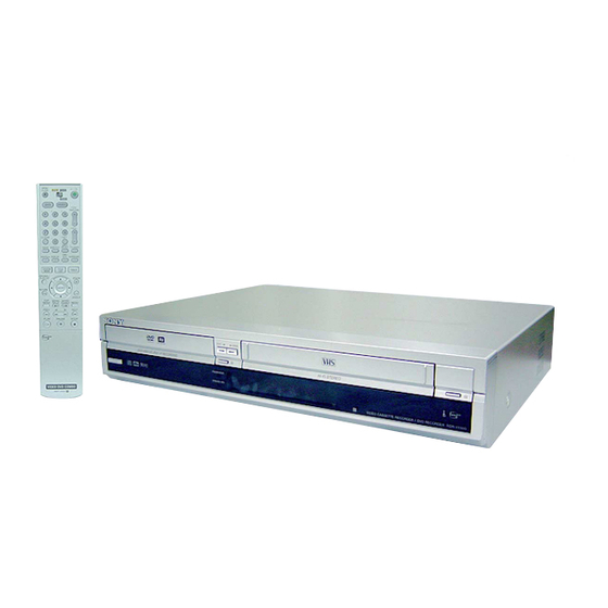
Sony RDR-VX500 Service Manual
Video cassette recorder/ dvd recorder
Hide thumbs
Also See for RDR-VX500:
- Service manual (132 pages) ,
- Operating instructions manual (128 pages) ,
- Specifications (2 pages)
Table of Contents
Advertisement
SERVICE MANUAL
System
DVD recorder section
Laser
Semiconductor laser
Audio recording format
Dolby Digital
Video recording format
MPEG Video
VCR section
Format
VHS NTSC standard
Video recording system
Ro
tary head helical scanning
FM system
Video heads
Double azimuth four heads
Video signal
NTSC color, EIA standards
Tape speed
3
SP: 33.35 mm/s (1
/
inches/s)
8
7
EP: 11.12 mm/s (
/
inches/s)
16
11
LP: 16.67 mm/s (
/
inches/s),
16
playback only
SPECIFICATIONS
Maximum recording/playback time
8 hrs. in EP mode (with T-160 tape)
Rewind time
Approx. 1 min (with T-120 tape)
Tuner section
Channel coverage
VHF 2 to 13
UHF 14 to 69
CATV A-8 to A-1, A to W, W+1 to
W+84
Antenna
75-ohm antenna terminal for VHF/UHF
Timer section
Clock
Quartz locked
Timer indication
12-hour cycle
Timer setting
12 programs in total (max.)
RDR-VX500
Canadian Model
Refer to the SERVICE MANUAL of VHS MECHANI-
CAL ADJUSTMENT MANUAL VII for MECHANICAL
ADJUSTMENTS. (9-921-790-11)
Inputs and outputs
LINE 1 IN and LINE 2 IN
VIDEO IN, phono jack (1 each)
Input signal: 1 Vp-p, 75 ohms,
unbalanced, sync negative
AUDIO IN, phono jacks (2 each)
Input level: 327 mVrms
Input impedance: more than 47 kilohms
LINE 2 IN
S VIDEO, 4-pin, mini-DIN jack
Y: 1.0 Vp-p, unbalanced, sync negative
C: 0.286 Vp-p, load impedance 75 ohms
DV IN, 4-pin jack, i.LINK S100
LINE OUT
VIDEO OUT, phono jack (1)
Output signal: 1 Vp-p, 75 ohms,
unbalanced, sync negative
AUDIO OUT, phono jacks (2)
Standard output: 327 mVrms
Load impedance: 47 kilohms
Output impedance: less than 10 kilohms
VIDEO CASSETTE RECORDER/
DVD RECORDER
RMT-V505
US Model
TS-10 MECHANISM
— Continued on next page —
Advertisement
Table of Contents

Related Manuals for Sony RDR-VX500


Summary of Contents for Sony RDR-VX500
- Page 1 RDR-VX500 RMT-V505 SERVICE MANUAL US Model Canadian Model TS-10 MECHANISM Refer to the SERVICE MANUAL of VHS MECHANI- CAL ADJUSTMENT MANUAL VII for MECHANICAL ADJUSTMENTS. (9-921-790-11) SPECIFICATIONS Inputs and outputs Maximum recording/playback time System 8 hrs. in EP mode (with T-160 tape)
- Page 2 DIGITA L AUDIO OUT General Dimensions including projecting parts and controls (w/h/d) OPTICAL, Optical output jack Power requirements Approx. 430 × 85 × 334 mm −18 dBm (wave length: 660 nm) 120 V AC, 60 Hz (Approx. 17 × 3.4 × 13 inches) COAXIAL, phono jack Power consumption...
- Page 3 SONY PARTS WHOSE PART NUMBERS APPEAR AS DE FONCTIONNEMENT. NE REMPLACER CES COM- SHOWN IN THIS MANUAL OR IN SUPPLEMENTS POSANTS QUE PAR DES PIÈCES SONY DONT LES PUBLISHED BY SONY. NUMÉROS SONT DONNÉS DANS CE MANUEL OU DANS LES SUPPLÉMENTS PUBLIÉS PAR SONY.
-
Page 4: Table Of Contents
TABLE OF CONTENTS Precautions Block Diagram ............3-1 Safety Precautions ······························································ 5 Servicing Precautions ························································ 7 PCB Diagrams ESD Precautions ································································· 8 VCR Main PCB ······························································· 4-3 Handling the Optical Pick-up ············································· 9 DVD Main PCB ······························································ 4-7 Jack PCB ······································································· 4-11 General DV Input PCB ·······························································... -
Page 5: Safety Precautions
PRECAUTIONS 1 SAFETY PRECAUTIONS 1) Before returning an instrument to the customer, always make a (4) Insulation Resistance Test Cold Check-(1) Unplug the power safety check of the entire instrument, including, but not limited supply cord and connect a jumper wire between the two prongs to, the following items: of the plug. - Page 6 6) Product Safety Notice-Some electrical and mechanical parts have special safety-related characteristics which are often not evident from visual inspection, nor can the protection they give necessarily be obtained by replacing them with components rated for higher voltage, wattage, etc. Parts that have special safety characteristics are identified by shading, an ( ) or a ( ) on...
-
Page 7: Servicing Precautions
2 SERVICING PRECAUTIONS CAUTION: Before servicing units covered by this service manual 2-2 Insulation Checking Procedure and its supplements, read and follow the Safety Precautions section of this manual. Disconnect the attachment plug from the AC outlet and turn the power ON. -
Page 8: Esd Precautions
3 ESD PRECAUTIONS Electrostatically Sensitive Devices (ESD) Some semiconductor (solid state) devices can be damaged easily by static electricity. Such components commonly are called Electrostatically Sensitive Devices (ESD). Examples of typical ESD devices are integrated circuits and some field-effect transistors and semiconductor chip components. -
Page 9: Handling The Optical Pick-Up
4 HANDLING THE OPTICAL PICK-UP The laser diode in the optical pick up may suffer electrostatic breakdown because of potential static electricity from clothing and your body. The following method is recommended. (1) Place a conductive sheet on the work bench (The black sheet used for wrapping repair parts.) (2) Place the set on the conductive sheet so that the chassis is grounded to the sheet. - Page 10 — 10 —...
-
Page 11: General
RDR-VX500 1. GENERAL This section is extracted from instruction manual. (2-186-506-11) About this manual Icon Meaning Ways to Use Your Video Cassette Recorder/DVD Recorder • Instructions in this manual describe the controls on the Functions available for DVD+RWs remote. You can also use the... - Page 12 • This VCR cannot record using the S-VHS system. • Tapes recorded in EP (3 × ) mode by this VCR cannot be RDR-VX500 played back on standard mode only VHS decks. • Noise may appear in the image when tapes recorded in EP (3 ×...
-
Page 13: Hookups And Settings
A: Cable box or satellite receiver with a video/audio output Step 2: Connecting the Hookups and Settings With this hookup, you can record any channel on the cable box or satellite receiver. Be sure that the Antenna Cable satellite receiver or cable box is turned on. Hooking Up the Recorder To watch cable or satellite programs, you need to match the channel on the recorder (L1) to the input jack connected to the cable box or satellite receiver (LINE 1 IN). - Page 14 Connecting to audio/video input If your TV has an S video input jack jacks Connect an S video cord (not supplied). You will enjoy high quality images. Make audio connections using the AUDIO OUT L/R jacks when you connect the recorder using this If your TV, monitor, projector, or other equipment connection.
- Page 15 AC outlet Surround2 Notes Manufactured under license from Dolby Laboratories. • If the supplied remote interferes your other Sony DVD “Dolby,” “Pro Logic,” and the double-D symbol are Player/Video Cassette Recorder or Video Cassette trademarks of Dolby Laboratories. Recorder/DVD Recorder, change the command mode “DTS”...
- Page 16 07, 10, 11 Sharp 03, 05, 18 ,continued Select “Options,” and press ENTER. Turn on the TV. If you have a Sony DVD Player/Video Step 7: Easy Setup Press "/1. Options 10:10 AM Cassette Recorder or Video The recorder turns on.
- Page 17 Select “Auto,” and press ENTER. Select the setting that matches your TV Select whether or not you want to send a ® Setting Up the VCR Plus+ The recorder will automatically search for a type. DTS signal to your amplifier (receiver), channel that carries a time signal when you and press ENTER.
-
Page 18: Basic Operation
Notes Connecting to the LINE 1 IN jacks • Do not connect the yellow LINE IN (VIDEO) jack when using an S video cord. You can connect a second VCR or similar device. • Do not connect the output jack of this recorder to another equipment’s input jack with the other equipment’s output jack connected to the input jack of this recorder. - Page 19 Press Z OPEN/CLOSE, and place a Press REC MODE repeatedly to select the Recording a Program to a Using the On-Screen Menus recordable disc on the disc tray. tape speed, “SP” or “EP.” “EP” (Extended Play) provides recording VHS Tape time three times as long as “SP”...
- Page 20 z Hints Press SYSTEM MENU while the recorder is Follow steps 1 to 6 of “Using the DVD Disc • You can set protection for individual titles (page 82). Using the DVD Disc Setting in stop mode. Setting Displays” on page 43 to select •...
-
Page 21: Dvd Recording
Recording mode Recording time Unrecordable pictures DVD Recording without the (minute) DVD Recording Pictures with copy protection cannot be recorded Timer HQ (High quality) on this recorder. Before Recording - RW - RW Copy control Recordable discs Video SP (Standard mode) signals Before you start recording…... - Page 22 E “CH”: Press DVD to control the DVD recorder. To confirm, change, or cancel timer recording Recording TV programs using the Selects the channel or input source. See “Checking/Changing/Canceling DVD Timer Press Z OPEN/CLOSE, and place a VCR Plus+ system Settings (Timer List)”...
-
Page 23: Playing Discs
Select the timer setting you want to check/ Press REC MODE repeatedly to select the Checking/Changing/ Recording from Connected change/cancel, and press ENTER. recording mode. The sub-menu appears. Each time you press the button, the display Canceling DVD Timer Equipment without a Timer changes on the TV screen as follows: Timer List 10:10 AM... - Page 24 Playback options Buttons Operations Discs SURROUND Selects one of the effects when pressed repeatedly. - RW - RW Video “Off”: No surround effect Z OPEN/CLOSE “Surround1”: Creates one set of virtual surround speakers. “Surround2”: Creates two sets of virtual surround speakers.
- Page 25 Select the desired directory, then press Notes Playing MP3 Audio Tracks Playing JPEG Image Files ENTER. • The recorder may not be able to play some DATA CDs Select the desired track, then press created in the Packet Write format. DATA CD DATA CD •...
-
Page 26: Vcr Recording
To stop recording Recording using the Quick Timer VCR Recording without the Press x STOP. VCR Recording (One-touch Timer Recording) Timer To pause recording You can set the recorder to record in 30 minute Before Recording Press X PAUSE. increments. To restart recording, press X PAUSE again. - Page 27 To use the Auto Tape Speed function Press the number buttons to enter the Recording TV programs using the Recording from Connected When you are recording a program in the Auto PlusCode number. VCR Plus+ system mode and the remaining tape becomes shorter than If you make a mistake, press CLEAR and re- Equipment with a Timer the recording time, the tape speed is automatically...
-
Page 28: Playing Vhs Tapes
Press REC MODE repeatedly to select the To stop playback Recording from Connected Press x STOP. tape speed, “SP” or “EP.” Playing VHS Tapes “EP” (Extended Play) provides recording Equipment without a Timer To eject the tape time three times as long as “SP” (Standard Playing Press Z OPEN/CLOSE. -
Page 29: Dvd Editing
Select “Go To Zero,” and press ENTER. Searching using the index function Searching Using Various Selecting the sound during The VCR starts searching and automatically (Scan and Play) stops at the 0:00:00 point. Functions playback The VCR automatically marks the tape with an index signal at the point where each recording The VCR automatically marks the tape with an begins. - Page 30 Select an option, and press ENTER. Press ENTER at the starting point of the Creating chapters manually Creating a Playlist You can make the following edits to the title. portion to be erased (point A). “Erase”: Erases the selected title. Select “OK” You can use H PLAY, - RW when asked for confirmation.
-
Page 31: Dubbing (Tapa Y Dvd)
To turn off the display To turn off the display Adding a scene (Add) Modifying a scene (Modify) Press SYSTEM MENU. Press SYSTEM MENU. - RW - RW Note Note The start and end point of a scene may be different from The start and end point of a scene may be different from You can add a scene before the selected scene. -
Page 32: Dv Dubbing (Dv Y Dvd)
Select “Dubbing,” and press ENTER. Using the DVD t button on the Notes Dubbing from a DVD to a Edit 10:10 AM • Dubbing is not possible when “Video” of “Progressive” recorder Video is set to “On” in the “Setup” display. Title List Create Playlist •... -
Page 33: Settings And Adjustments
Select “Audio,” and press ENTER. Select “DV Edit,” and press ENTER. Select “Setup,” and press ENTER. The display for recording and “DV Tape The “Setup” display appears. Audio 10:10 AM Settings and Adjustments Mode” appear. Setup 10:10 AM Title list Tuner Audio : Main If “DV Tape Mode”... - Page 34 ◆ Time Zone 16:9 Clock Setting (Clock Set) Select the time zone for your area, or select Video Settings (Video) “Auto” to have the recorder automatically set your time zone. The “Clock Set” setup helps you to make clock Video settings will adjust items related to the The options are: setting for the recorder.
- Page 35 For details, see “If you have a Timer Create the password. The “Options” setup appears with the displayed. Sony DVD Player/Video Cassette Recorder or following options. The default settings are Edit Video Cassette Recorder/DVD Recorder” on Parental 10:10 AM underlined.
-
Page 36: Additional Information
Should any problem persist, , Adjust the picture (see the TV’s instruction Select “Setup,” and press ENTER. consult your nearest Sony dealer. manual). , Place the recorder and TV farther apart. Select “Easy Setup,” and press ENTER. - Page 37 Remote control the video heads using a Sony video head cleaning This is because the recorder is adding disc data to , The safety tab has been removed. To record on cassette.
- Page 38 X (pause) button (48, 59, 67, 78) equipment to be connected. x (stop) button (37, 48, 57, 67, 76, 89) Required i.LINK cable Use the Sony i.LINK 4-pin-to-4-pin cable (during DV dubbing). i.LINK and are trademarks. ,continued...
- Page 39 Remote for VIDEO Front panel display A TV/DVD·VIDEO switch (27) Buttons on the remote have the same function as the buttons on the recorder if they have the same B Z OPEN/CLOSE (eject) button (76) or similar names. Buttons with an orange dot next C Number buttons (27, 71)* to them can be used with your TV when the TV/ RW VR VCD...
- Page 40 MEMO 1-30E...
-
Page 41: Disassembly And Reassembly
RDR-VX500 2. DISASSEMBLY AND REASSEMBLY 2-1 CABINET AND PCB 2-1-1 Cabinet Top Removal 2-1-3 Ass’y Front Panel Removal Lift up the Cabinet Top in the direction of arrow. 1 REMOVE 1 RELEASE 3 HOOKS 3 SCREWS Fig. 2-3 Ass’y Front Panel Removal (Top View) Fig. -
Page 42: Chassis Removal
2-1-4 Chassis Removal 2 REMOVE 4 SCREWS 3 REMOVE 4 SCREWS 1 REMOVE 2 SCREWS VCR DECK DVD DECK 4 REMOVE 7 SCREWS VCR MAIN PCB SHIELD CASE-GROUND PCB JACK PCB DVD MAIN PCB DV INPUT PCB FUNCTION TIMER PCB Fig. -
Page 43: Circuit Board Locations
2-2 CIRCUIT BOARD LOCATIONS Fig. 2-7 Circuit Board Locations... -
Page 44: Vcr Deck Parts Locations
2-3 VCR DECK PARTS LOCATIONS 2-3-1 Top View Fig. 2-8 Top parts Location-1 1 GEAR FL CAM 2 MOTOR LOADING ASS’Y 3 LEVER FL ARM ASS’Y 4 HOLDER FL CASSETTE ASS’Y 5 LEVER FL DOOR 6 SLIDER FL DRIVE... - Page 45 9 q; qa q; qs Fig. 2-9 Top Parts Location-2 1 FE HEAD 8 DISK S REEL 2 CYLINDER ASS’Y 9 LEVER S BRAKE ASS’Y 3 ACE HEAD ASS’Y 0 GEAR IDLE 4 LEVER UNIT PINCH ASS’Y qa LEVER IDLE 5 LEVER #9 GUIDE ASS’Y qs LEVER T BRAKE ASS’Y 6 LEVER TENSION ASS’Y...
-
Page 46: Bottom View
2-3-2 Bottom View Fig. 2-10 Bottom Parts Location 1 GEAR JOINT 1 2 GEAR JOINT 2 3 BRAKET GEAR 4 MOTOR CAPSTAN ASS’Y 5 LEVER T LOAD ASS’Y 6 GEAR LOADING DRIVE 7 LEVER S LOAD ASS’Y 8 HOLDER CLUTCH ASS’Y 9 BELT PULLEY 0 SLIDER CAM... -
Page 47: Vcr Deck
2-4 VCR DECK 2-4-1 Holder FL Cassette Ass’y Removal 2-4-2 Lever FL Arm Ass’y Removal 1) Pull the Holder FL Cassette Ass’y 1 to the eject position. 1) Push the hole “A” in the direction of arrow “B” use the pin.(about 2) Pull the Holder FL Cassette Ass’y 1 as grasping the Holder FL Dia. -
Page 48: Lever Fl Door Removal
2-4-3 Lever FL Door Removal 2-4-4 Slider FL Drive, Gear FL Cam Removal 1) Release the Hook 2 and Remove the Lever FL Door 1 in the 1) Pull the Slider FL Drive 1 to the front direction. direction of arrow “A”. 2) Remove the Slider FL Drive 1 in the direction of arrow. -
Page 49: Gear Worm Wheel Removal
2-4-5 Gear Worm Wheel Removal 2-4-6 Cable Flat Removal 1) Remove the Gear Worm wheel 1. 1) Remove the Drum connecting part of Cable Flat 1 from Connector Wafer 2. 2) Remove the Loading Motor connecting part of Cable Flat 1 from Connector Wafer 3. -
Page 50: Motor Loading Ass'y Removal
2-4-7 Motor Loading Ass’y Removal 2-4-8 Bracket Gear, Gear Joint 2, 1 Removal 1) Remove the Screw 1. 1) Remove the Screw 1. 2) Remove the Motor Loading Ass’y 2. 2) Remove the Bracket Gear 2. 3) Remove the Gear Joint 2 3. 4) Remove the Gear Joint 1 4. -
Page 51: Gear Loading Drive, Slider Cam
2-4-9 Gear Loading Drive, Slider Cam, 2-4-10 Gear Loading Drive, Slider Cam, Lever Load S, T Ass’y Removal Lever Load S, T Ass’y Assembly 1) Remove the Belt Pulley. (Refer to Fig. 2-38) 1) When reinstalling, be sure to align dot of Lever Load T Ass’y 2) Remove the Gear Loading Drive 1 after releasing Hook [A] in 1 with dot of Lever Load S Ass’y 2 as shown in drawing, the direction arrow as shown in detail drawing. -
Page 52: Lever Pinch Drive, Lever Tension Drive Removal
2-4-11 Lever Pinch Drive, 2-4-12 Lever Tension Ass’y, Lever Tension Drive Removal Band Brake Ass’y Removal 1) Remove the Lever Pinch Drive 1, Lever Tension Drive 2. 1) Remove the Lever Brake S Ass’y (Refer to Fig 2-25). 2) Remove the Spring Tension Lever 1. 1 LEVER PINCH DRIVE 3) Rotate stopper of Main Base in the direction of arrow “A”. -
Page 53: Lever Brake S, T Ass'y Removal
2-4-13 Lever Brake S, T Ass’y Removal 2-4-14 Gear Idle Ass’y Removal 1) Release the Hook [A] and the Hook [B], [C] in the direction of 1) Push the Lever Idle 1 in the direction of arrow “A”, “B”. arrow as shown in Fig 2-25. 2) Lift the Lever Idle 1. -
Page 54: Disk S, T Reel Removal
2-4-15 Disk S, T Reel Removal 2-4-16 Holder Clutch Ass’y Removal 1) Lift the Disk S, T Reel 1, 2. 1) Remove the Washer Slit 1. 2) Lift the Holder Clutch Ass’y 2. Note: When you reinstall Holder Clutch Ass’y 1) Check the condition of spring as shown in detail A. -
Page 55: Lever Up Down Ass'y, Gear Center Ass'y Removal
2-4-17 Lever Up Down Ass’y, Gear Center 2-4-18 Guide Cassette Door Removal Ass’y Removal 1) Lift the Hook [A]. 2) Rotate the Guide Cassette Door 1 in the direction of arrow. 1) Remove the 2 hooks in the direction of arrow as shown Fig. 2- 29 and lift the Lever Up Down Ass’y 1. -
Page 56: Lever Unit Pinch Ass'y, Plate Joint
2-4-19 Lever Unit Pinch Ass’y, Plate Joint, 2-4-20 Lever #9 Guide Ass’y Removal Spring Pinch Drive Removal 1) Remove the Spring #9 Guide 1. 2) Lift the Lever #9 Guide Ass’y 2 in the direction of arrow “A”. 1) Lift the Lever Unit Pinch Ass’y 1. 2) Remove the Plate Joint 2 from Lever Pinch Drive. -
Page 57: Fe Head Removal
2-4-21 FE Head Removal 2-4-22 ACE Head Removal 1) Lift the FE Head 1. 1) Pull out the FPC from connector of ACE Head Ass’y 2. 2) Remove the Screw 1. 3) Lift the ACE Head Ass’y 2. 1 FE HEAD 1 SCREW HEAD ACE ASS`Y Fig. -
Page 58: Slider S, T Ass'y Removal
2-4-23 Slider S, T Ass’y Removal 2-4-24 Plate Ground Deck, Cylinder Ass’y Re- moval 1) Move the Slider S, T Ass’y 1, 2 to slot, and then lift it to remove. (Refer to arrow) 1) Remove the 3 Screws 1. 2) Lift the Plate Ground Deck 2. -
Page 59: Hook Capstan, Belt Pulley Removal
2-4-25 Hook Capstan, Belt Pulley Removal 2-4-26 Motor Capstan Ass’y Removal 1) Remove the Hook Capstan 1 after realeasing Hook in the 1) Remove the 3 Screws 1. direction arrow as shown in detail drawing. 2) Remove the Motor Capstan Ass’y 2. 2) Remove the Belt Pulley 2. -
Page 60: Post #8 Guide Ass'y Removal
2-4-27 Post #8 Guide Ass’y Removal 2-4-29 How to Eject the Cassette Tape (If the unit does not operate on condition 1) Rotate the Post #8 Guide Ass’y 1 in the direction of arrow to that is inserted into housing ass’y) lift up. -
Page 61: The Table Of Cleaning, Lubrication And Replacement Time About Principal Parts
2-5 THE TABLE OF CLEANING, LUBRICATION AND REPLACEMENT TIME ABOUT PRIN- CIPAL PARTS 1) The replacement time of parts is not life of parts. 2) The table 2-1 is that the VCR Set is in normal condition (normal temperature, normal humidity). The checking period may be changed owing to the condition of use, runtime and environmental conditions. - Page 62 MEMO 2-22E...
-
Page 63: Block Diagram
RDR-VX500 3. Block Diagram 4MB FLASH EEPROM 8MB(x2) SDRAM K8D3216UBM 24LC32 DVD-Rewritable Drive (32bit) (8bit) (I2C) ND-2500A/REC RF Out VHF/UHF TM BLOCK CVBS MTS IC 2MB(x4) SDRAM DVD V IN ENCODER 6CH AMP DECODER LA72670 (64bit) LA73054 CS92686 CS98202 L/R from Tuner... - Page 64 MEMO 3-4E...
-
Page 65: Pcb Diagrams
RDR-VX500 4. PCB Diagrams 4-1 VCR Main PCB - - - - - - - - - - - - - - - - - - - - - - - - - - - - - - - - - - - - - - - - 4-3... -
Page 66: Vcr Main Pcb
4-1 VCR Main PCB COMPONENT SIDE... - Page 67 CONDUCTOR SIDE...
-
Page 68: Dvd Main Pcb
4-2 DVD Main PCB COMPONENT SIDE... - Page 69 CONDUCTOR SIDE 4-10...
-
Page 70: Jack Pcb
4-3 Jack PCB COMPONENT SIDE 4-11 4-12... - Page 71 CONDUCTOR SIDE 4-13 4-14...
-
Page 72: Dv Input Pcb
4-4 DV Input PCB COMPONENT SIDE CONDUCTOR SIDE 4-5 Function Timer PCB COMPONENT SIDE CONDUCTOR SIDE 4-15 4-16E... -
Page 73: Schematic Diagrams
RDR-VX500 5. Schematic Diagrams Block Identification of Main PCB - - - - - - - - - - - - - - - - - - - - - - - - - - - - - - 5-3 Note 5-1 S.M.P.S (VCR Main PCB) - - - - - - - - - - - - - - - - - - - - - - - - - - - - - - - - - 5-5... -
Page 74: Vcr Main Pcb
Block Identification of Main PCB VCR MAIN PCB <Component Side> <Component Side>... - Page 75 5-1 S.M.P.S. (VCR Main PCB)
-
Page 76: Power (Vcr Main Pcb)
5-2 Power (VCR Main PCB) -
Page 77: Logic (Vcr Main Pcb)
5-3 Logic (VCR Main PCB) 5-10... -
Page 78: A/V (Vcr Main Pcb)
5-4 A/V (VCR Main PCB) 5-11 5-12... -
Page 79: Hi-Fi (Vcr Main Pcb)
5-5 Hi-Fi (VCR Main PCB) 5-13 5-14... -
Page 80: Function Timer (Function Timer Pcb)
5-6 Function Timer (Function Timer PCB) 5-15 5-16... -
Page 81: Encoder (Dvd Main Pcb)
5-7 Encoder (DVD Main PCB) M D [31:0] C HANG E Par t T ype( FB23, FB24, FB25, FB26) 3225 to 2012 C9 8 ADD R132, R133, C40 0,C 401(041204) P3V3 P3V3 OPEN C40 0 OPEN C40 1 OPEN SM1V8 P3V3 FB2 3 FB2 4 ADD C98, R29 f or EM I modif y... -
Page 82: Decoder (Dvd Main Pcb)
5-8 Decoder (DVD Main PCB) V_ R _O U T V_R _O U T AD C _B C K [2,6] Y _G_ OUT Y_ G _O U T P C MI_LRCK [2 ,4 ] U_ B _O U T P C MI_D A T A [2,4] U_ B _O U T IO _R XD... -
Page 83: Video Decoder And Connector (Dvd Main Pcb)
5-9 Video Decoder and Connector (DVD Main PCB) Cha nge Value 22pF to 33pF (C12,C1 3) C 12 33pF Cha nge Value 1M to 100K 14.318 MHz (R54 ) Change Par t T ype(FB2,FB3, FB4 ,F B5) P3V3 VDEC_3V3D C 13 33pF R 54 100K... -
Page 84: Dv Interface And 1394 Connector (Dvd Main Pcb)
5-10 DV Interface and 1394 Connector (DVD Main PCB) Chang e V alue 27pF t o 20pF (C 1,C 2) P3V3 24.576M H Z Add C228 f or ESD M odify C L = 20p F C2 28 20pF 20pF OPEN A N A LO G _RST~ [3 ,4 ,6]... -
Page 85: Audio Dac And Adc (Dvd Main Pcb)
5-11 Audio DAC and ADC (DVD Main PCB) Chang e Par t T ype(F B16,F 17) 3225 t o 2012 P12V0 P3V3 P3V3_ D IG P5V0_ D IG FB1 6 FB1 7 0(2012) 0(2012) C1 85 C 183 0 .1 u F/25V/Y 5V C 184 0 .1 u F/25V/Y 5V R 148 9.1K... -
Page 86: Connectors And Power (Dvd Main Pcb)
5-12 Connectors and Power (DVD Main PCB) CN 3 5V to 3.3V regulator for T I T VP5146 (278R33 Fairchild) CN 1 G N D P3V3 G N D V 3.3 LINE2 V IN BEAD_45 32 V 3.3 AVI N(F RI) SUPER V IN C3 08 C3 09... -
Page 87: Mts/Tuner (Jack Pcb)
5-13 Mts/Tuner (JACK PCB) 5-29 5-30... -
Page 88: Av In/Out (Jack Pcb)
5-14 AV IN/OUT (JACK PCB) 5-31 5-32... -
Page 89: Component/Super Out (Jack Pcb)
5-15 Component/Super Out (JACK PCB) 5-33 5-34... - Page 90 MEMO 5-36E...
-
Page 91: Alignment And Adjustments
RDR-VX500 6. ALIGNMENT AND ADJUSTMENTS 6-1 VCR ADJUSTMENT 6-1-1 Reference 1) X-Point (Tracking center) adjustment, “Head switching adjustment” can be adjusted with remote control. 2) When replacing the Main PCB Micom (IC601) and NVRAM (IC603: EEPROM) be sure to adjust the “Head switching adjustment”. - Page 92 6-1-1(b) TEST location for adjustment mode setting Short-Circuit for few seconds and release. (Just one time) Fig. 6-2 Function Timer PCB (Top View)
-
Page 93: Head Switching Point Adjustment
6-1-2 Head Switching Point Adjustment 1) Playback the alignment tape. 2) Intermittently short-circuit the two Test Points on Function Timer PCB while setting the adjustment mode. (See Fig. 6-2) 3) Press the “1, 0” buttons ; remote control adjustment operates automatically. (See Fig. 6-1) -
Page 94: Vcr Mechanical Adjustment
6-2 VCR MECHANICAL ADJUSTMENT 6-2-1 Tape Transport System and Adjustment Locations The tape transport system has been adjusted precisely in the factory. Alignment is not necessary except for the following : 1) Noise observed on the screen. 2) Tape damage. 3) Parts replacement in the tape transport system. -
Page 95: Tape Transport System Adjustment
6-2-2 Tape Transport System Adjustment When parts are replaced, perform the required adjustments by referring to procedures for the tape transport system. If there are any changes to the tape path, first run a T-120 tape and make sure excessive tape wrinkle does not occur at the tape guides. If tape wrinkle is observed at the guide roller S, T, turn the guide roller S, T until wrinkle disappears. - Page 96 b. ACE HEAD TILT ADJUSTMENT 1) Playback a blank tape and observe the position of the tape at the lower flange of tape guide. 2) Confirm that there is no curl or wrinkle at the lower flange of tape guide as shown in Fig. 6-7 (B). 3) If a curl or wrinkle of the tape occurs, slightly turn the screw (A) tilt adjust on the ACE head ass’y.
- Page 97 d. ACE HEAD POSITION (X-POINT) ADJUSTMENT 1) Playback the alignment tape (Color bar) 2) Intermittently short-circuit the two Test Points on Function Timer PCB. (See Fig. 6-2) 3) Press the “0, 5” remote control buttons, then adjustment is operates automatically. (See Fig. 6-1) 4) Connect the CH-1 probe to “Envelope”...
- Page 98 (2) Linearity adjustment (Guide roller S, T adjustment) 1) Playback the Mono Scope alignment tape (SP mode). 2) Observe the video envelope signal on an oscilloscope (triggered by the video switching pulse). 3) Make sure the video envelope waveform (at its minimum) meets the specification shown in Fig. 6-9. If it does not, adjust as follows : Note: a=Maximum output of the video RF envelope.
- Page 99 6) Play back the Mono Scope alignment tape (SP mode). 7) Connect an oscilloscope CH-1 to the “Envelope” and CH-2 to the “H’D SW Pulse” for triggering. 8) Turn the guide roller heads with a flat head ( ) driver to obtain a flat video RF envelope as shown in Fig. 6-11. IDEAL ENVELOPE S HEIGHT TOO HIGH T HEIGHT TOO HIGH...
-
Page 100: Reel Torque
(4) Envelope Check 1) Make recordings on T-120 (E-120) and T-160 (E-180) tape. Make sure the playback output envelope meets the specification as shown in Fig. 6-13. 2) Play back a self recorded tape (recording made on the unit using with T-120 (E-120). The video envelope should meet the specification as shown in Fig. - Page 101 No Power Detected Key Operation or (stand by LED OFF) Remote Control Error Is the measurement of F1S01 is normal? Change fuse Check power and front connector power with in normal value? Change short circuited or BD01~04, ZD1S01~2 XT601 14.318MHz Check the circuity around the clock opened parts SHORT and OPEN...
- Page 102 PLAY MODE MECHANISM DOESN'T (VCR Section) (VCR Section) INOPERATIVE OPERATE IN PLAY MODE TURN VCR POWER ON EE-VIDEO (VIDEO MISSING IN EE MODE) LOAD A TAPE AND PRESS PLAY BUTTON INSERT THE CASETTE TAPE RECORDED BY ANOTHER VCR AND PRESS PLAY BUTTON (LOAD) CHECK IC601-59:HIGH...
- Page 103 RECORD MODE (VCR Section) DOESN'T OPERATE CAPSTAN (CAPSTAN DOES NOT ROTATION ROTATE) PLAY (PLAY MODE OPERATION DOESN'T OPERATE) LOAD VCR WITH A TAKE UP REEL SENSOR (S.T REEL) BLANK TAPE AND SUPPLY REEL SENSOR PRESS RECORD BUTTON IC601-1.2 (PT601.PT602) PULSE EJECT CHANGE TAPE REC MODE...
- Page 104 FAST FORWARD FWD SEARCH DOESN'T (VCR Section) (VCR Section) DOESN'T OPERATE OPERATE LOAD TAPE AND PRESS F.FWD BUTTON PLAY (PLAY DOESN'T OPERATE) OPERATION F.FWD PRESS FF INDICATOR IN CHANGE IC601, XT601 KEY IN REMOTE THE DISPLAY CONTROL PRESS F.FWD FOR FORWARD SEARCH CHECK TIMER IS CAPSTAN...
- Page 105 CASSETTE LOADING VIDEO MISSING IN MECHANISM (VCR Section) (VCR Section) DOES NOT OPERATE EE MODE TURN THE VCR PLACE VCR IN STOP MODE POWER ON AND INSERT A TAPE LINE 2 INPUT CHECK CST IN MODE TAPE DETECTED START SENSOR (S601) IC601-87:HIGH(5V) IC601 IC301-53,54...
- Page 106 VIDEO MISSING IN VIDEO MISSING IN (VCR Section) (VCR Section) RECORD MODE PLAY MODE IC301-21pin E-E mode and IC301-26pin VIDEO signal out? CHECK VIDEO signal out SEE PAGE 7-5 VIDEO EE MODE (VIDEO MISSING IN EE MODE) OPERATION IC301-22pin CHECK C305 VIDEO signal out? PLACE THE VCR PLAY MODE IC301-14pin...
- Page 107 COLOR MISSING IN COLOR MISSING IN (VCR Section) NOTE: XT301 - Always (3.579545MHz) (VCR Section) NOTE: XT301 - Always (3.579545MHz) RECORD MODE PLAY MODE SEE PAGE 7-6 (VIDEO IN) FM-ENV SEE PAGE 7-6 (VIDEO MISSING IN RECORD RECORD MODE IC301-14 (VIDEO MISSING IN PLAY MODE) MODE) COLOR signal...
- Page 108 OSD PICTURE BLUE MISSING IN (VCR Section) (VCR Section) STOP MODE MISSING SELECT LINE MODE WITHOUT INPUT SIGNAL CHECK IC601-37, 38pin CHECK C618,C619 14.318MHz signal out CHECK IC601-37, 38pin CHECK C618, C619 14.318MHz out CHECK IC601-52,53pin CHECK C626, R639 AFC signal out CHANGE IC601 CHECK IC601-52, 53pin CHECK C626, R639...
- Page 109 AUDIO MISSING IN AUDIO MISSING IN (VCR Section) (VCR Section) EE MODE (VCR Section) REC MODE VCR STOP MODE CHECK AUDIO MISSING IN EE MODE IC801-44, 46, CHECK L1/L2 INPUT CHOICE 56, 58pin Audio C819, C820, MODE C825, C826 signal input MONO MISSING AUDIO TUNER...
- Page 110 AUDIO MISSING MONO (VCR Section) IN PB MODE CHECK CHECK AUDIO MISSING IN PB MODE PB MODE CHECK "AUDIO MISSING IN EE MODE" IC301-76 IC501-4 CHECK AUDIO SIGNAL AUDIO SIGNAL C336, R322, R348 PLACE THE VCR IN PB MODE CHANGE IC501 IC301-10 CHECK MONO...
- Page 111 CAPSTAN DOES (VCR Section) (VCR Section) NO SERVO LOCK NOT ROTATE PLAY CHECK CN604-2 B+ IN THE POWER BLOCK CHECK IC601-68 CN604-1 C-FG CHECK CN604-3 5V AT AL5V LINE AL 5V IN THE POWER BLOCK IC601-76 CTL PULSE PLACE THE VCR IN PLAY MODE CHECK CTL PULSE AC...
- Page 112 DRUM DOES (VCR Section) NOT ROTATE CHECK CN604-6 12V AT PC12V LINE IN THE POWER BLOCK CN604-3 CHECK 5V LINE CN604-12 CN601-34 PWM OUT CHANGE IC601 2.5V CHECK CHECK CYLINDER MOTOR R631, R617, R618, C609, C610...
- Page 113 Disc loading error Are main and deck Check the power power OK? Is the FFC cable (between main & deck) Reinsert FFC cable correctly inserted correctly? Change the main board...
- Page 114 No Analog Audio Output No digital audio out Checking Voltage of L802 is 9V Check the digital audio Power block Replace Jack board Refer to user manual (jack PCB) setting Skip setting check (hardware problem) Check the pin #13, #20 Check IC501 #3pin Sdata Proper vcc of DOL3 (jack PCB) Check Vcc Line...
- Page 115 No audio on line input mode or CVBS output error recorded disc playback Check select signal of 15, 17, 12, 11 in CN1 check pin63, 64 (input select)of IC801 pin44, 46, 56, 58 in IC801 Check SMPS block of Jack PCB has (jack board) normal level? Analog signals are...
- Page 116 S-Video output error Component output error 6 and 7pin in CN1 of 6pin and 7pin in CN1 of jack PCB or CN01 of main Check main PCB Check main PCB. jack PCB or CN01 of main PCB PCB has normal level? has normal level? Analog signals are Check the connection between6 and...
- Page 117 Line1 CVBS Video Input Error Pin4 in IC801 Check the connection between has nomal level? pin4 in IC801 and L1 pin-jack (jack PCB) Pin21 in IC801 Check pin 62, 55 in IC801 of input power has nomal level? Check the connection between pin80 Pin80 in IC301 sonata main PCB in IC301 of sonata main PCB has nomal level?
- Page 118 Line2 S-Video Video Input Error Line2 CVBS Video Input Error Pin 6 in IC801 Pin 26, 28 in CN1 Check the connection between pin 26 Check the connection between has nomal level? has nomal level and 28 in CN1 and L2 S- videojack pin 6 in IC801 and L2 pin-jack (jack PCB) (jack PCB)
-
Page 119: Repair Parts List
RDR-VX500 8. REPAIR PARTS LIST 8-1 Exploded Views ---------------------------------------------------------------------- 8-2 8-1-1 Cabinet Assembly ---------------------------------------------------------------------------------- 8-2 8-1-2 VCR Mechanical Parts (Top Side) --------------------------------------------------------------- 8-3 8-1-3 VCR Mechanical Parts (Bottom Side) ----------------------------------------------------------- 8-4 8-2 Electrical Parts List ------------------------------------------------------------------ 8-5... -
Page 120: Exploded Views
8-1 EXPLODED VIEWS NOTE: • -XX, -X mean standardized parts, so they may • The mechanical parts with no reference number The components identified by mark have some differences from the original one. in the exploded views are not supplied. dotted line with mark are critical for safety. -
Page 121: Vcr Mechanical Parts (Top Side)
8-1-2 VCR Mechanical Parts (Top Side) T016 T001 T030 not supplied T015 not supplied not supplied not supplied T009 W016 not supplied T008 T010 T014 T025 T023 T024 T003 T028 T019 W201 not supplied not supplied T027 not supplied not supplied T033 T020 not supplied... -
Page 122: Vcr Mechanical Parts (Bottom Side)
8-1-3 VCR Mechanical Parts (Bottom Side) T046 W018 not supplied not supplied T044 not supplied not supplied not supplied not supplied not supplied not supplied supplied not supplied not supplied not supplied not supplied not supplied W019 Ref. No. Part No. Description Remarks Ref. -
Page 123: Electrical Parts List
DVD MAIN FUNCTION TIMER JACK 8-2 ELECTRICAL PARTS LIST • Items marked “*” are not stocked since they are NOTE: When indicating parts by reference number, • Due to standardization, replacements in the seldom required for routine service. Some delay please include the board name. - Page 124 JACK VCR MAIN Ref. No. Part No. Description Remarks Ref. No. Part No. Description Remarks AZ51 9-885-070-22 DIODE-ZENER UDZ9.1B VCR MAIN BOARD AZ52 9-885-070-22 DIODE-ZENER UDZ9.1B *************** AZ53 9-885-070-22 DIODE-ZENER UDZ9.1B AZ55 9-885-070-22 DIODE-ZENER UDZ9.1B 9-885-069-99 ASSY PCB-MAIN AZ56 9-885-070-22 DIODE-ZENER UDZ9.1B SC1P05 9-885-069-85 SCREW-TAPTITE ZPC (YEL) SWR AZ57...
- Page 125 VCR MAIN Ref. No. Part No. Description Remarks Ref. No. Part No. Description Remarks ZD1S02 9-885-070-23 DIODE-ZENER MTZJ18C Q1P107 9-885-070-32 TR-SMALL SIGNAL KSC945 Q1P108 9-885-070-31 TR-SMALL SIGNAL KSC2328A-Y < FUSE > Q1P109 9-885-070-31 TR-SMALL SIGNAL KSC2328A-Y Q1P110 9-885-070-31 TR-SMALL SIGNAL KSC2328A-Y 0 F1S01 9-885-069-78 FUSE-CARTRIDGE (1.6A/250V)
- Page 126 RDR-VX500 Sony Corporation 2004I0500-1 Home Electronics Network Company © 2007. 11 — 154 — 9-874-845-12 Published by Quality Assurance Dept.