Advertisement
Quick Links
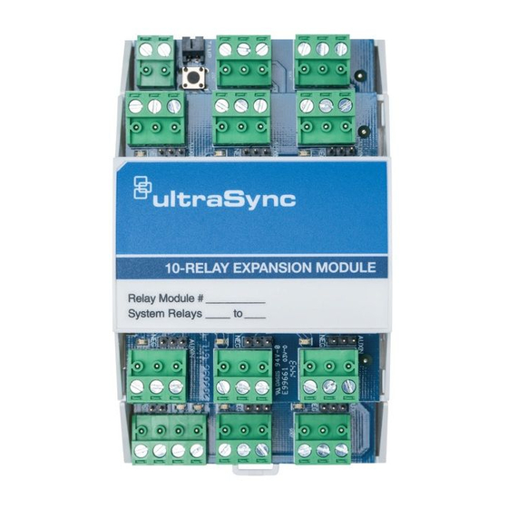
UltraSync Modular Hub
TM
Relay Expansion Module
Installation Sheet
UM-R4
UM-R10
English Installation Sheet
Product Summary:
1. Tamper input.
Disabled by default. Connect
tamper switch when mounted in
a separate enclosure from CPU.
Enable in \Devices\System
Devices\Relay
Expanders\Expander Options.
2. Manual enroll button
3. Bus and Neg/Aux jumpers. See
below for configuration details.
4. TERM (bus termination). Correct
RS-485 termination reduces
communication issues with
signal reflections. For a single
long cable run, put a jumper
across the terminal labeled
TERM on the CPU and the
furthest bus device. For
installations with multiple long
cable runs, (star configurations)
do not place a terminator on the
CPU; rather place one at the end
of each of the two longest cable
runs.
Installation
1.
Pull down the din rail tab on the bottom of the module.
UM-R4
2.
Hang the module on the top of the din rail, tilting the
bottom of the module outward. Once the module is
vertical, lock the module on the rail by pushing the tab up.
© 2017 United Technologies Corporation
These modules add 4 or 10 relay outputs to an UltraSync Modular Hub system.
2
1
3
UM-R10
(pictured)
or UM-R4
4
PLEASE READ THE ULTRASYNC MODULAR HUB REFERENCE GUIDE BEFORE
USING THIS PRODUCT WHICH INCLUDES IMPORTANT SAFETY AND LEGAL
INFORMATION INCLUDING WARNINGS, WARRANTY DISCLAIMERS, AND
LIMITATIONS OF LIABILITY, AND COMPLETE INSTRUCTIONS ON HOW TO ENROLL
AND CONFIGURE EXPANSION MODULES. THE REFERENCE GUIDE IS AVAILABLE
AT: http://www.interlogix.com/intrusion/product/ultrasync-modular-hub
S'IL VOUS PLAÎT LIRE LE GUIDE DE REFERENCE POUR LE HUB UltraSync
MODULAIRE AVANT D'UTILISER CE PRODUIT QUI COMPREND LA SÉCURITÉ
IMPORTANT ET JURIDIQUES INFORMATIONS, Y COMPRIS LES AVERTISSEMENTS,
GARANTIE EXCLUSIONS, ET LIMITATIONS DE RESPONSABILITÉ ET INSTRUCTIONS
COMPLETES SUR COMMENT ENROLLER ET CONFIGURER LES MODULES
D'EXPANSION. LE GUIDE DE RÉFÉRENCE
EST DISPONIBLE AU: http://www.interlogix.com/intrusion/product/ultrasync-modular-hub.
3.
Connect the POS, NEG, LAN+ and LAN-
5.
Install a TERM (bus termination) jumper if required.
See above for guidance.
6.
Enroll the expansion module in your system. To manually
enroll the module, use the web interface. In the advanced
menu, navigate to Devices – System Devices – Control
– Enroll Function and select Manual Enroll from the
drop down menu. This puts the system into manual
enrollment mode. When the CPU is in the manual
enrollment mode, simply push ENROLL button on the
module to enroll the module into the system. Hold the
button down for three seconds.
1 / 2
466-5273 • REV C • ISS 14FEB17
Advertisement

Summary of Contents for Interlogix UltraSync UM-R4
- Page 1 GARANTIE EXCLUSIONS, ET LIMITATIONS DE RESPONSABILITÉ ET INSTRUCTIONS COMPLETES SUR COMMENT ENROLLER ET CONFIGURER LES MODULES UM-R10 D’EXPANSION. LE GUIDE DE RÉFÉRENCE EST DISPONIBLE AU: http://www.interlogix.com/intrusion/product/ultrasync-modular-hub. English Installation Sheet Product Summary: These modules add 4 or 10 relay outputs to an UltraSync Modular Hub system.
- Page 2 PROTECTION TEMPORAIRE. SI ELLE EST ACTIVÉE, VOTRE GROUPE PRÉSENTERA Interlogix is a registered trademark of United Technologies SON RAPPORT "SURINTENSITÉ" OU "EXPANDER SURVOLTAGE." CONDITIONS DE Corporation. Interlogix is part of UTC Climate, Controls & SURINTENSITÉ RÉPÉTÉ PEUT ENTRAÎNER UN ENDOMMAGEMENT PERMENANT AU PANNEAU OU A DES APPAREILS CONNECTÉS.