Table of Contents
Advertisement
Quick Links
Installation and Maintenance Instructions
CONTENTS
SAFETY CONSIDERATIONS . . . . . . . . . . . . . . . . . . . 1
GENERAL . . . . . . . . . . . . . . . . . . . . . . . . . . . . . . . . . . . 2
DIMENSIONS. . . . . . . . . . . . . . . . . . . . . . . . . . . . . . . . . 4
FAN CURVE CHARACTERISTICS. . . . . . . . . . . . . . . 5
INSTALLATION . . . . . . . . . . . . . . . . . . . . . . . . . . . . . . . 7
Step 1 - Unpack and Inspect Units . . . . . . . . . . . . 7
Step 2 - Position the Unit . . . . . . . . . . . . . . . . . . . 8
Step 3 - Mount the Unit . . . . . . . . . . . . . . . . . . . . . . 8
Step 4 - Connect Piping . . . . . . . . . . . . . . . . . . . . . . 9
Step 6 - Installing the LED Display Panel . . . . . 12
Step 7 - Position and Connect Controller . . . . . 12
MAINTENANCE . . . . . . . . . . . . . . . . . . . . . . . . . . . 16
TROUBLESHOOTING . . . . . . . . . . . . . . . . . . . . . . 19
REPLACEMENT PARTS. . . . . . . . . . . . . . . . . . . . . 21
APPENDIX - DIP SWITCH SETTINGS . . . . . . . . . . 22
SAFETY CONSIDERATIONS
Improper installation, adjustment, alteration, service,
maintenance, or use can cause explosion, fire, electrical shock,
or other conditions; which may cause death, personal injury or
property damage. The qualified installer or agency must use
factory-authorized kits or accessories when modifying this
product.
Follow all safety codes. Wear safety glasses, protective
clothing, and work gloves. Use quenching cloth for brazing
operations. Have fire extinguisher available. Read these
instructions thoroughly and follow all warnings or cautions
included in the literature and attached to the unit. Consult local
building codes and the current editions of the National
Electrical Code (NEC) ANSI/NFPA (American National
Standards Institute/National Fire Protection Association) 70. In
Canada, refer to the current editions of the Canadian Electrical
Code CSA (Canadian Standards Association) C22.1.
Understand the signal words - DANGER, WARNING, and
CAUTION. DANGER identifies the most serious hazards,
which result in severe personal injury or death. WARNING
signifies hazards that could result in personal injury or death.
CAUTION is used to identify unsafe practices, which would
result in minor personal injury or product and property
damage.
Recognize safety information. This is the safety-alert
symbol (
). When this symbol is displayed on unit and in
instructions or manuals, be alert to potential for personal
injury.
WARNING
Electrical shock can cause personal injury and death.
Shut off all power to this equipment during installation.
There may be more than one disconnect switch. Tag all
disconnect locations to alert others not to restore power
until work is completed.
Manufacturer reserves the right to discontinue, or change at any time, specifications or designs without notice and without incurring obligations.
Catalog No.20-40VMZ001-01
Page
Printed in U.S.A.
Form 40VMZ-1SI
Variable Refrigerant Flow (VRF) Systems
DO NOT re-use compressor oil or any oil that has been
exposed to the atmosphere. Dispose of oil per local codes
and regulations. DO NOT leave refrigerant system open to
air any longer than the actual time required to service the
equipment. Seal circuits being serviced and charge with dry
nitrogen to prevent oil contamination when timely repairs
cannot be completed. Failure to follow these procedures
may result in damage to equipment.
For information about replacement oil type and viscosity,
see the Installation, Start-Up, and Service Instructions for
the 38VMAH and 38VMAR outdoor units.
DO NOT USE TORCH to remove any component. The
system contains oil and refrigerant under pressure.
To remove a component, wear protective gloves and
goggles and proceed as follows:
A. Shut off electrical power to unit.
B. Recover refrigerant to relieve all pressure from the
system using both the high-pressure and low
pressure ports.
C. Traces of vapor should be displaced with nitrogen
and the work area should be well ventilated.
Refrigerant in contact with an open flame produces
toxic gases.
D. Cut the component connection tubing with a tubing
cutter and remove the component from unit. Use a
pan to catch any oil that may come out of the lines
and as a gage for how much oil to add to the system.
E. Carefully unsweat remaining tubing stubs when
necessary. Oil can ignite when exposed to torch
flame.
Failure to follow these procedures may result in personal
injury or death.
When installing the equipment in a small space, provide
adequate measures to avoid refrigerant concentration
exceeding safety limits due to refrigerant leak.
In case of refrigerant leak during installation, ventilate
the space immediately. Failure to follow this procedure
may lead to personal injury.
Pg 1
40VMZ009-024
Reheat Unit for
WARNING
WARNING
WARNING
08-20
Replaces: New
Advertisement
Table of Contents

Related Manuals for Carrier 40VMZ


Summary of Contents for Carrier 40VMZ
-
Page 1: Table Of Contents
Manufacturer reserves the right to discontinue, or change at any time, specifications or designs without notice and without incurring obligations. Catalog No.20-40VMZ001-01 Printed in U.S.A. Form 40VMZ-1SI Pg 1 08-20 Replaces: New... -
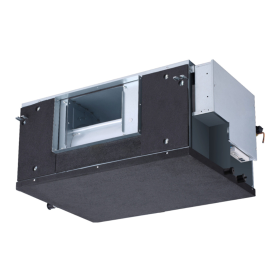
Page 2: General
GENERAL The 40VMZ reheat ducted indoor fan coil unit offers simple operation and long service with proper installation, operation, and regular maintenance. The equipment is initially protected under the manufacturer's standard warranty; however, the warranty is provided under the condition that the steps outlined in this manual for initial inspection, proper installation, regular periodic maintenance, and everyday operation of the unit be followed in detail. - Page 3 Table 2 — 40VMZ Physical Data UNIT 40VMZ 208/230-1-60 POWER SUPPLY (V-Ph-Hz) 9,000 12,000 15,000 18,000 24,000 HEATING CAPACITY (Btuh) INDOOR FAN MOTOR Type Input (W) INDOOR COIL Number of Rows Fin Spacing (fins/in.) Hydrophilic Aluminum Fin Type Tube Diameter, OD (in.)
-
Page 4: Dimensions
DIMENSIONS 37-1/2 33- 3/4 3-3/8 8-7/16 16-7/8 PLASTIC COVER ELECTRICAL CONTROL BOX FRONT AIR INTAKE 4-12*25 OBLONG SUSPENTION BOLT HOLES CONNECTING POINT OF DRAIN PIPE 31-1/2 REFRIGERANT-PIPE FLANED REFRIGERANT-PIPE FLANED AIR OUTLET DUCT FLANGE INTAKE DUCT CONNECTION SAFETY DRAIN CONNECTING PIPE 1-5/16 AIR OUTLET RIGHT SIDE... -
Page 5: Fan Curve Characteristics
FAN CURVE CHARACTERISTICS Fig. 3 —Size 009 Fig. 4 —Size 012 Range of Available Airflow Rate in H-Speed Range of Available Airflow Rate in H-Speed Max Point Rating Point Min Point Max Point Rating Point Min Point Speed Speed (in.) (in.) (in.) (in.) - Page 6 Fig. 6 —Size 018 Fig. 5 —Size 015 Range of Available Airflow Rate in H-Speed Range of Available Airflow Rate in H-Speed Max Point Rating Point Min Point Max Point Rating Point Min Point Speed Speed (in.) (in.) (in.) (in.) (in.) (in.) 0.20...
-
Page 7: Installation
NOTES for Figs. 4 - 8 1. There are multiple ESP settings available for each ducted unit. 2. All fan curves show examples of fan characteristics of the "MAX. ESP," "RATING ESP," and "MIN. ESP" settings; these curves are shown for High (H), Medium (M), and Low (S) speeds, as selected by the user at the controller. -
Page 8: Step 2 - Position The Unit
PREPARING JOB SITE FOR UNIT INSTALLATION — To If a 2-ft. clearance is not possible, follow the minimum save time and to reduce possible costly errors, set up a maintenance clearances as shown in Fig. 9. complete sample installation in a typical room at the job site. Check all critical dimensions such as pipe, wire, and duct connections requirements. -
Page 9: Step 4 - Connect Piping
Follow these recommendations when installing condensate piping (optional): • Condensate piping should slope downward in the direction of condensate flow with a minimum gradient of 1 inch per 100 inches. See Fig. 13. Fig. 11 —Threaded Rod Fig. 13 —Using a Main Drain to Serve Multiple Step 4 —... -
Page 10: Step 5 - Complete The Electrical Connections
See Table 4 for electrical data. • The bending angle of the refrigerant pipe should not exceed 90 and the bending radius should be as large as Table 4 —40VMZ Electrical Data possible to prevent any breakage in piping. Power Supply •... - Page 11 Outside Air Unit No Beep Harness Display Board Fig. 15 —40VMZ009-024 Typical Wiring Diagram LEGEND: — Auxiliary Control Board ALARM — Warning Lamp AUXH — Output for Auxiliary Heat — Condensate Switch CTON — Output for Cooling Operation — Electronic Expansion Valve —...
-
Page 12: Step 6 - Installing The Led Display Panel
Step 6 — Installing the LED Display Panel — Step 7 — Position and Connect Controller — 1. The display panel has buckles on the bottom that are used Wired controllers should be installed in a position that to secure it to the control box. See Fig. 16. maintains good temperature control: •... - Page 13 Fig. 22 Fig. 23 —Connecting the Communication Wires If it is not possible to buy communication wires from Carrier, connect the indoor unit side of the communication wires using the connector provided with the accessories as shown in Fig.
- Page 14 wired controller outdoor unit Centralized controller Indoor unit 1# Outside Air Unit wired controller CN50 CN51 FAN CTON HTON AUXH ACB interface CN54 OFF GND wired controller Indoor unit 2# Main MDC unit Reheat unit wired controller Indoor unit 3# Indoor unit 4# wired controller MDC unit...
- Page 15 IMPORTANT: The system can connect 64 indoor units with START-UP — different system addresses. If two indoor units in the same sys- Pre-Start Check — tem have identical addresses, abnormal operation will occur. Once installation is complete, perform the following pre-start ACB Interface (Reserved)—...
-
Page 16: Maintenance
MAINTENANCE CAUTION FAN ASSEMBLY MAINTENANCE: — Refer to the To avoid equipment damage, do not attempt to reuse any following figures and instructions for removing fan assemblies mechanical or electrical controllers that have been as needed for repair and service. exposed to moisture. - Page 17 Fig. 30 —Fan Disassembly (009-024) 1. Horizontally push the fan assembly until it cannot move any further. See Fig. 30. 2. Lift up slightly and take it down to remove it. 3. After motor maintenance, reinstall the fan assemblies (apply steps in reverse order (step 2 then step 1)). 4.
- Page 18 Wireless Remote Controller (40VM900001) — Programmable Controller — When setting an address, connect only one wired controller to an indoor unit. Indoor unit addressing can be performed using the wireless remote controller. When using the wireless controller, the 1. Press FAN and BACK simultaneously for five seconds to user must maintain a line of sight with the receiver on the access the parameter settings as shown in Fig.
-
Page 19: Troubleshooting
TROUBLESHOOTING Figure 35 shows the LED display panel on the indoor unit. Table 5 provides a summary of display indicators. Table 6 lists problems, possible causes, and possible solutions. MANUAL OPERATION TIMER DEF./FAN ALARM Fig. 35 —LED Display Panel Table 5 —LED Display Indicators ERROR CODE LED DISPLAY MODE/STATUS... - Page 20 Table 6 —Troubleshooting ERROR DESCRIPTION POSSIBLE CAUSES POSSIBLE SOLUTIONS System is in cooling or fan only mode, and All units should be in cooling mode for Heating / Cooling Mode Conflict heating signal is received from a unit on the system to stay in cooling mode system System is in heating mode, and...
-
Page 21: Replacement Parts
750 W (33/32HP) REFRIGERANT R410A HIGH 580 PSIG DESIGN PRESSURE 320 PSIG SERIAL NO. Carrier Corporation Fig. 36 —Unit Serial Plate (Example) Fig. 37 —Filter Unit Size Filter Dimension (W x H x D) 009 to 024 28-3/8 x 13-1/4 x 3/8... -
Page 22: Appendix - Dip Switch Settings
Fig. B —SW8 Settings Fig. A — SW1 Settings © Carrier Corporation 2020 Manufacturer reserves the right to discontinue, or change at any time, specifications or designs without notice and without incurring obligations. Catalog No.20-40VMZ001-01 Printed in U.S.A.