
Related Manuals for Komatsu 140-3 Series


Summary of Contents for Komatsu 140-3 Series
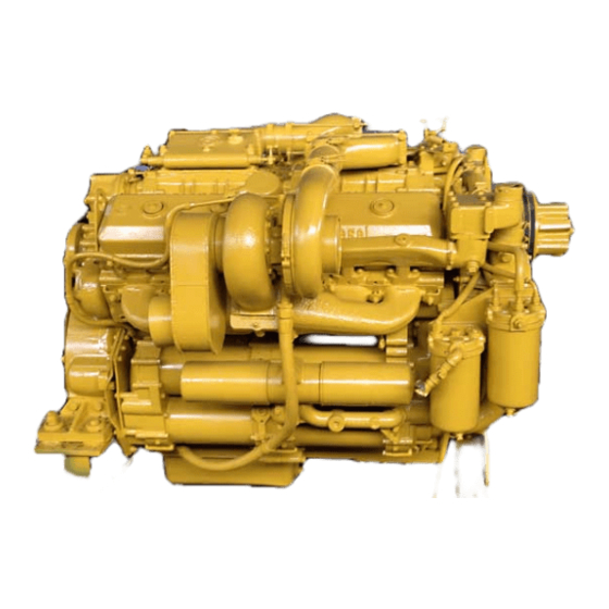
- Page 1 SEBM022209 DIESEL ENGINE © 2003 All Rights Reserved Printed in Japan 11-03 (01) 00-1...
-
Page 2: Table Of Contents
CONTENTS No. of page 01 GENERAL ..........................01-1 11 STRUCTURE AND FUNCTION, MAINTENANCE STANDARD ..........11-1 12 TESTING AND ADJUSTING ................ 12-1 13 DISASSEMBLY AND ASSEMBLY ............13-1 15 REPAIR AND REPLACEMENT OF PARTS ....................15-1 00-2 140-3 SERIES... - Page 3 11-47 11-76 00-19 01-70 11-17 11-48 11-77 00-20 01-71 11-18 11-49 11-78 00-21 01-72 11-19 11-50 11-79 00-22 01-73 11-20 11-51 11-80 01-90 11-22 11-52 11-81 11-23 11-53 11-82 01-1 11-24 11-54 11-83 01-2 11-25 11-56 11-84 00-2-1 140-3 SERIES...
- Page 4 12-113 12-230 13-9 13-50 12-4 12-114 12-231 13-10 13-51 12-5 12-115 12-232 13-11 13-52 12-5-1 12-116 12-233 13-12 13-53 12-6 12-117 12-234 13-13 13-54 12-7 12-118 12-235 13-14 13-55 12-8 12-119 12-236 13-15 12-9 12-120 12-237 13-16 00-2-2 140-3 SERIES...
- Page 5 Time of Time of Mark Page Mark Page Mark Page Mark Page Mark Page revision revision revision revision revision 15-1 15-2 15-3 15-4 15-5 15-6 15-7 15-8 15-9 15-10 15-11 15-12 15-13 15-14 15-15 15-16 15-17 15-18 00-2-3 140-3 SERIES...
- Page 7 Proper service and repair is extremely important for safe machine operation. The service and repair techniques recommended by Komatsu and described in this manual are both effective and safe. Some of these techniques require the use of tools specially designed by Komatsu for the specific purpose.
- Page 8 SAFETY SAFETY NOTICE PRECAUTIONS DURING WORK 19.Be sure to assemble all parts again in their origi- nal places. 11. When removing the oil filler cap, drain plug or Replace any damaged parts with new parts. hydraulic pressure measuring plugs, loosen •...
- Page 9 FOREWORD GENERAL FOREWORD GENERAL This shop manual has been prepared as an aid to improve the quality of repairs by giving the serviceman an accurate understanding of the product and by showing him the correct way to perform repairs and make judge- ments.
- Page 10 DISTRIBUTION AND UPDATING Any additions, amendments or other changes will be Symbol Item Remarks sent to KOMATSU distributors. Get the most up-to- date information before you start any work. Special safety precautions ¤ Safety are necessary when per- forming the work.
- Page 11 FOREWORD HOISTING INSTRUCTIONS HOISTING INSTRUCTIONS HOISTING Slinging near the edge of the hook may cause ¤ the rope to slip off the hook during hoisting, and H eavy parts (25 kg or more) must be lifted a serious accident can result. Hooks have max- with a hoist, etc.
- Page 12 FOREWORD METHOD OF DISASSEMBLING, CONNECTING PUSH-PULL TYPE COUPLER METHOD OF DISASSEMBLING, CONNECTING PUSH-PULL TYPE COUPLER ¤ B efore carrying out the following work, release Type 1 the residual pressure from the hydraulic tank. For details, see TESTING AND ADJUSTING, Releasing residual pressure from hydraulic tank.
- Page 13 FOREWORD METHOD OF DISASSEMBLING, CONNECTING PUSH-PULL TYPE COUPLER Type 2 Type 3 1) Hold the mouthpiece of the tightening portion 1) Hold the mouthpiece of the tightening portion and push body (2) in straight until sliding pre- and push body (2) in straight until sliding pre- vention ring (1) contacts contact surface a of vention ring (1) contacts contact surface a of the hexagonal portion at the male end.
- Page 14 The recommended coating materials such as adhesives, gasket sealants and greases used for disassembly and assembly are listed below. For coating materials not listed below, use the equivalent of products shown in this list. Category Komatsu code Part No. Q'ty Container Main applications, featuresr •...
- Page 15 FOREWORD COATING MATERIALS Category Komatsu code Part No. Q'ty Container Main applications, featuresr • Ftures: Silicon based, quick hard- ening type LG-7 790-129-9070 Tube • Used as sealant for flywheel housing, intake manifold, oil an, Adhesives thermostat housing, etc. •...
- Page 16 FOREWORD STANDARD TIGHTENING TORQUE STANDARD TIGHTENING TORQUE STANDARD TIGHTENING TORQUE TABLE (WHEN USING TORQUE WRENCH) In the case of metric nuts and bolts for which there is no special instruction, tighten to the torque given in the table below. Thread diameter Width across of bolt flats...
- Page 17 FOREWORD STANDARD TIGHTENING TORQUE TABLE OF TIGHTENING TORQUES FOR SPLIT FLANGE BOLTS In the case of split flange bolts for which there is no special instruction, tighten to the torque given in the table below. Thread diameter Width across flat Tightening torque 65.7 11.5...
- Page 18 FOREWORD STANDARD TIGHTENING TORQUE TIGHTENING TORQUE FOR 102 ENGINE SERIES 1) BOLT AND NUTS Use these torques for bolts and nuts (unit: mm) of Cummins Engine. Thread diameter Tightening torque 1.02 0.20 2.45 0.41 4.38 0.61 7.85 1.22 2) EYE JOINTS Use these torques for eye joints (unit: mm) of Cummins Engine.
- Page 19 FOREWORD ELECTRIC WIRE CODE ELECTRIC WIRE CODE In the wiring diagrams, various colors and symbols are employed to indicate the thickness of wires. This wire code table will help you understand WIRING DIAGRAMS. Example: 5WB indicates a cable having a nominal number 5 and white coating with black stripe. CLASSIFICATION BY THICKNESS Copper wire Current...
- Page 20 FOREWORD CONVERSION TABLE CONVERSION TABLE METHOD OF USING THE CONVERSION TABLE The Conversion Table in this section is provided to enable simple conversion of figures. For details of the method of using the Conversion Table, see the example given below. EXAMPLE •...
- Page 21 FOREWORD CONVERSION TABLE Millimeters to Inches 1 mm = 0.03937 in 0.039 0.079 0.118 0.157 0.197 0.236 0.276 0.315 0.354 0.394 0.433 0.472 0.512 0.551 0.591 0.630 0.669 0.709 0.748 0.787 0.827 0.866 0.906 0.945 0.984 1.024 1.063 1.102 1.142 1.181 1.220 1.260...
- Page 22 FOREWORD CONVERSION TABLE Liter to U.S. Gallon 1 l = 0.2642 U.S. Gal 0.264 0.528 0.793 1.057 1.321 1.585 1.849 2.113 2.378 2.642 2.906 3.170 3.434 3.698 3.963 4.227 4.491 4.755 5.019 5.283 5.548 5.812 6.076 6.340 6.604 6.869 7.133 7.397 7.661 7.925...
- Page 23 FOREWORD CONVERSION TABLE kgm to ft. lb 1 kgm = 7.233 ft. lb 14.5 21.7 28.9 36.2 43.4 50.6 57.9 65.1 72.3 79.6 86.8 94.0 101.3 108.5 115.7 123.0 130.2 137.4 144.7 151.9 159.1 166.4 173.6 180.8 188.1 195.3 202.5 209.8 217.0 224.2...
- Page 24 FOREWORD CONVERSION TABLE kg/cm to lb/in 1kg/cm = 14.2233 lb/in 14.2 28.4 42.7 56.9 71.1 85.3 99.6 113.8 128.0 142.2 156.5 170.7 184.9 199.1 213.4 227.6 241.8 256.0 270.2 384.0 398.3 412.5 284.5 298.7 312.9 327.1 341.4 355.6 369.8 426.7 440.9 455.1 469.4...
- Page 25 FOREWORD CONVERSION TABLE Temperature Fahrenheit-Centigrade Conversion ; a simple way to convert a Fahrenheit temperature reading into a Cen- tigrade temperature reading or vice versa is to enter the accompanying table in the center or boldface col- umn of figures. These figures refer to the temperature in either Fahrenheit or Centigrade degrees.
- Page 26 FOREWORD UNITS UNITS In this manual, the measuring units are indicated with Internatinal System of units (SI). As for reference, conventionally used Gravitational System of units are indicated in parentheses { Example: N {kg} Nm {kgm} MPa {kg/cm kPa {mmH kPa {mmHg} kW/rpm {HP/rpm} g/kWh {g/HPh}...
-
Page 27: 01 General
01 GENERAL OUTLINE ..............................01- SPECIFICATIONS ............................01- OVERALL DRAWING..........................01- 20 WEIGHT TABLE ............................01- 28 ENGINE PERFORMANCE CURVE ......................01- 50 01-1 140-3 SERIES... -
Page 28: Outline
Generator HD325-6 Dump truck HM350-1 Articulated dump truck HM350-1 (–40°C spec.) Articulated dump truck SAA6D140E-3 HM400-1 Articulated dump truck PC750-6, PC750LC-6, PC750-7 Hydraulic excavator PC800-6, PC800-7 Hydraulic excavator PC1800-6 (USA) Hydraulic excavator D275A-5 Bulldozer SDA6D140E-3 D275AX-5 Bulldozer 01-2 140-3 SERIES... - Page 29 4) The turbocharger is an improved version of the Komatsu KTR110 turbocharger job proven on the 140E- 2 engine, which boasts high reliability and high performance. The improved points are the supply air recirculation port to control the surge at the compressor end and the high efficiency design added to the turbine.
- Page 30 This will reduce the service life of the engine; in particular, excessive load will be applied to the turbocharger. To prevent this, a turbo protect system has been installed to limit the engine speed. 01-4 140-3 SERIES...
- Page 32 24V, 11kW 24V, 11kW 24V, 11kW Battery — 12V 170Ah x 2 12V 170Ah x 2 12V 170Ah x 2 Turbocharger — Komatsu KTR110L Komatsu KTR110L Komatsu KTR110L Air compressor — — — — Others — With aftercooler With aftercooler...
- Page 33 Electronic control type (71) (37) 27 (Engine only) 26 (Engine only) 24V, 35A 24V, 75A 24V, 7.5kW 24V, 11kW 12V 200Ah x 2 12V 170Ah x 2 Komatsu KTR110L Komatsu KTR110L — — With aftercooler With aftercooler 01-7 140-3 SERIES...
- Page 34 Starting motor — 24V, 11kW 24V, 11kW Battery — 12V 170Ah x 2 12V 170Ah x 2 Turbocharger — Komatsu KTR110L Komatsu KTR110L Air compressor — — Zexel Recipro type single cylinder (only for front engine) Others — With air-cooled...
- Page 35 Komatsu KTR110L Komatsu KTR110L Komatsu KTR110L Zexel Recipro type — — — single cylinder With air-cooled With air-cooled With air-cooled With air-cooled aftercooler and aftercooler and aftercooler and aftercooler and exhaust brake exhaust brake exhaust brake exhaust brake 01-9 140-3 SERIES...
-
Page 36: Specifications
Lubricating oil amount (replacement amount) (55) Cooling water 26 (Engine only) Alternator — 24V, 75A Starting motor — 24V, 11kW Battery — 12V 170Ah x 2 Turbocharger — Komatsu KTR110L Air compressor — — Others — With aftercooler 01-10 140-3 SERIES... -
Page 38: Overall Drawing
GENERAL OVERALL DRAWING OVERALL DRAWING The diagram shows the equipment for the WA500-3. SA6D140E-3 LEFT SIDE DRAWING The shape may differ according to the machine model. a. Crankshaft center b. Flywheel housing rear surface 01-20 140-3 SERIES... - Page 39 GENERAL OVERALL DRAWING SA6D140E-3 FRONT DRAWING + The diagram shows the equipment for the WA500-3. + The shape may differ according to the machine model. a. Crankshaft center b. Cylinder liner center 01-21 140-3 SERIES...
- Page 40 GENERAL OVERALL DRAWING SAA6D140E-3 LEFT SIDE DRAWING + The diagram shows the equipment for the HM350-1 and HM400-1. + The shape may differ according to the machine model. a. Crankshaft center b. Flywheel housing rear surface 01-22 140-3 SERIES...
- Page 41 GENERAL OVERALL DRAWING SAA6D140E-3 FRONT DRAWING + The diagram shows the equipment for the HM350-1 and HM400-1. + The shape may differ according to the machine model. a. Crankshaft center b. Cylinder liner center 01-23 140-3 SERIES...
- Page 42 GENERAL OVERALL DRAWING SDA6D140E-3 LEFT SIDE DRAWING + The diagram shows the equipment for the D275AX-5. + The shape may differ according to the machine model. a. Crankshaft center b. Flywheel housing rear surface 01-24 140-3 SERIES...
- Page 43 GENERAL OVERALL DRAWING SDA6D140E-3 FRONT DRAWING + The diagram shows the equipment for the D275AX-5. + The shape may differ according to the machine model. a. Crankshaft center b. Cylinder liner center 01-25 140-3 SERIES...
- Page 44 1,000 1,185 PC800-6, PC800-7 SAA6D140E-3 PC1800-6 (USA) 1,624 1,625 1,000 1,185 HD325-6 1,686 1,585 — — — 1,156 HM350-1, HM400-1 1,642 1,469 146.5 146.5 Dimensions for each part (mm) Engine Machine model D275A-5, D275AX-5 1,461 2,020 SDA6D140E-3 01-26 140-3 SERIES...
-
Page 46: Weight Table
24V 50A 24V 75A 12.5 14 Alternator PC800-6 (USA) 24V 90A — PC800-7 (USA) PC1800-6 (USA) 24V 7.5kW 15.5 15.5 15 Starting motor 24V 11kW 16 Air compressor PC750-6,PC750-7 PC800-6,PC800-7 PC1800-6 17 Aftercooler assembly HD325-6 HM350-1 HM400-1 01-28 140-3 SERIES... - Page 47 GENERAL WEIGHT TABLE Unit : kg SDA6D140E-3 22.5 x 6 D275A-5 D275AX-5 D275A-5 D275AX-5 D275A-5 D275AX-5 10.7 x 6 — — 12.5 — — — 01-29 140-3 SERIES...
-
Page 48: Engine Performance Curve
Engine Serial No. Machine model Page PC600-6 01-51 110001 – 112349 D155AX-5 01-52 SA6D140E-3 112350 and up D155AX-5 01-52-1 WA500-3 01-53 HD325-6 01-70 PC750, PC750LC-6, PC750-7 PC800-6, PC800-7 01-71 SAA6D140E-3 PC1800-6 HM350-1 01-72 HM400-1 01-73 D275A-5, D275AX-5 01-90 SAD6D140E-3 01-50 140-3 SERIES... - Page 49 GENERAL ENGINE PERFORMANCE CURVE SA6D140E-3 [For PC600-6] Rated output: 287kW {385HP} / 1,800 rpm (Net) Max. torque: 1,755 Nm {179 kgm} / 1,400 rpm (Net) 01-51 140-3 SERIES...
- Page 50 GENERAL ENGINE PERFORMANCE CURVE SA6D140E-3 [For D155AX-5 (110001 – 112349)] Rated output: 252kW {338HP} / 1,900 rpm (Gross) Max. torque: 1,635 Nm {166.7 kgm} / 1,250 rpm (Gross) 01-52 140-3 SERIES...
- Page 51 GENERAL ENGINE PERFORMANCE CURVE SA6D140E-3 [For D155AX-5 (112350 and up)] Rated output: 248kW {332HP} / 1,900 rpm (Gross) Max. torque: 1,635 Nm {166.7 kgm} / 1,250 rpm (Gross) 01-52-1 140-3 SERIES...
- Page 53 GENERAL ENGINE PERFORMANCE CURVE SA6D140E-3 [For WA500-3] Rated output: 235kW {316HP} / 2,100 rpm (Net) Max. torque: 1,370 Nm {140 kgm} / 1,400 rpm (Net) 01-53 140-3 SERIES...
- Page 54 GENERAL ENGINE PERFORMANCE CURVE SAA6D140E-3 [For HD325-6] Rated output: 379kW {508HP} / 2,000 rpm (Gross) Max. torque: 2,170 Nm {221 kgm} / 1,400 rpm (Gross) 01-70 140-3 SERIES...
- Page 55 GENERAL ENGINE PERFORMANCE CURVE SAA6D140E-3 [For PC750-6, PC750LC-6, PC750-7, PC800-6, PC800-7, PC1800-6] Rated output: 338kW {454HP} / 1,800 rpm (Net) Max. torque: 2,138 Nm {218 kgm} / 1,350 rpm (Net) 01-71 140-3 SERIES...
- Page 56 GENERAL ENGINE PERFORMANCE CURVE SAA6D140E-3 [For HM350-1] Rated output: 298kW {399HP} / 2,000 rpm (Gross) Max. torque: 1,950 Nm {199 kgm} / 1,400 rpm (Gross) 01-72 140-3 SERIES...
- Page 57 GENERAL ENGINE PERFORMANCE CURVE SAA6D140E-3 [For HM400-1] Rated output: 335kW {444HP} / 2,000 rpm (Gross) Max. torque: 2,048 Nm {209 kgm} / 1,400 rpm (Gross) 01-73 140-3 SERIES...
- Page 58 GENERAL ENGINE PERFORMANCE CURVE SDA6D140E-3 [For D275A-5, D275AX-5] Rated output: 335kW {446HP} / 2,000 rpm (Gross) Max. torque: 1,990 Nm {203 kgm} / 1,400 rpm (Gross) 01-90 140-3 SERIES...
-
Page 59: 11 Structure And Function
VALVE, VALVE GUIDE......11- 44 AIR COMPRESSOR........ 11- 95 ROCKER ARM AND SHAFT....11- 46 EXHAUST BRAKE........11- 98 CROSSHEAD AND GUIDE ..... 11- 47 ELECTRICAL COMPONENTS ALTERNATOR ......... 11-101 STARTING MOTOR......... 11-106 STARTING AID ........11-108 11-1 140-3 SERIES... -
Page 60: Intake, Exhaust Equipment
STRUCTURE AND FUNCTION, MAINTENANCE STANDARD INTAKE, EXHAUST EQUIPMENT INTAKE, EXHAUST EQUIPMENT SA6D140E-3 (Left side face of engine) The diagram shows the equipment for the PC600-6. Details may change for reasons such as modification. 1. Aftercooler 2. Intake manifold 11-2 140-3 SERIES... - Page 61 The diagram shows the equipment for the PC600-6. Details may change for reasons such as modification. 1. Turbocharger A. Intake inlet 2. Muffler B. Exhaust outlet 3. Exhaust manifold (front) 4. Exhaust manifold (center) 5. Exhaust manifold (rear) 11-3 140-3 SERIES...
- Page 62 STRUCTURE AND FUNCTION, MAINTENANCE STANDARD INTAKE, EXHAUST EQUIPMENT SA6D140E-3 (Front face of engine) The diagram shows the equipment for the PC600-6. Details may change for reasons such as modification. 1. Electric heater (electrical intake air heater) 2. Intake manifold 11-4 140-3 SERIES...
- Page 63 STRUCTURE AND FUNCTION, MAINTENANCE STANDARD INTAKE, EXHAUST EQUIPMENT SA6D140E-3 (Rear face of engine) The diagram shows the equipment for the PC600-6. Details may change for reasons such as modification. 1. Exhaust manifold 2. Turbocharger 11-5 140-3 SERIES...
- Page 64 STRUCTURE AND FUNCTION, MAINTENANCE STANDARD INTAKE, EXHAUST EQUIPMENT SAA6D140E-3 (Left side face) The diagram shows the equipment for the HD325-6. Details may change for reasons such as modification. 1. Connector (between air-cooled aftercooler and intake manifold) 2. Intake manifold 11-6 140-3 SERIES...
- Page 65 2. Turbocharger B. Exhaust outlet 3. Intake connector C. Air supply (between turbocharger and air-cooled aftercooler) 4. Exhaust manifold (front) D. Air supply (between air-cooled aftercooler and air supply manifold) 5. Exhaust manifold (center) 6. Exhaust manifold (rear) 11-7 140-3 SERIES...
- Page 66 STRUCTURE AND FUNCTION, MAINTENANCE STANDARD INTAKE, EXHAUST EQUIPMENT SAA6D140E-3 (Front face) The diagram shows the equipment for the HD325-6. Details may change for reasons such as modification. 1. Electric heater (electrical intake air heater) 2. Intake manifold 11-8 140-3 SERIES...
- Page 67 STRUCTURE AND FUNCTION, MAINTENANCE STANDARD INTAKE, EXHAUST EQUIPMENT SAA6D140E-3(Rear face) The diagram shows the equipment for the HD325-6. Details may change for reasons such as modification. 1. Exhaust manifold 2. Turbocharger 11-9 140-3 SERIES...
- Page 68 STRUCTURE AND FUNCTION, MAINTENANCE STANDARD + The diagram shows the equipment for the SDA6D140E-3 (Left side face of engine) D275AX-5. + Details may change for reasons such as modification. 1. Aftercooler 2. Intake manifold 11-9-1 140-3 SERIES...
- Page 69 + The diagram shows the equipment for the D275AX-5. + Details may change for reasons such as modification. 1. Turbocharger A. Intake inlet 2. Exhaust manifold (front) B. Exhaust outlet 3. Exhaust manifold (center) 4. Exhaust manifold (rear) 11-9-2 140-3 SERIES...
- Page 70 STRUCTURE AND FUNCTION, MAINTENANCE STANDARD SDA6D140E-3 (Front face of engine) + The diagram shows the equipment for the D275AX-5. + Details may change for reasons such as modification. 1. Electric heater (electrical intake air heater) 2. Intake manifold 11-9-3 140-3 SERIES...
- Page 71 STRUCTURE AND FUNCTION, MAINTENANCE STANDARD SDA6D140E-3 (Rear face of engine) + The diagram shows the equipment for the D275AX-5. + Details may change for reasons such as modification. 1. Exhaust manifold 2. Turbocharger 11-9-4 140-3 SERIES...
-
Page 72: Air Cleaner
C. To muffler (dust) 4. Precleaner Dust discharge Engine Machine model Type No. of elements method for precleaner D155AX-5 SA6D140E-3 Komaclone, multicyclone Automatic discharge Inner cylinder 1, (110001 – 112349) type (EGB type) (exhaust ejector) Outer cylinder 1 SAA6D140E-3 HD325-6 11-10 140-3 SERIES... - Page 73 4. Inner element Dust discharge Engine Machine model Type No. of elements method for precleaner D275A-5 SDA6D140E-3 D275AX-5 Komaclone, multicyclone Automatic discharge Inner cylinder 1, type (ERB type) (exhaust ejector) Outer cylinder 1 D155AX-5 SA6D140E-3 (112350 and up) 11-11 140-3 SERIES...
-
Page 76: Turbocharger
D. Exhaust outlet Overall width: 305mm 5. Shroud E. Oil inlet Overall height: 287mm 6. Turbine housing F. Oil outlet Weight: 24kg 7. Turbine impeller 8. Seal ring 9. Bearing 10. Thrust bearing 11. Seal ring 12. Blower impeller 11-12 140-3 SERIES... - Page 77 TURBOCHARGER KTR110L (WATER-COOLED TYPE) 1. Blower housing A. Intake inlet Specifications 2. V-band B. Intake outlet Type: Komatsu KTR110L (water-cooled) 3. Diffuser plate C. Exhaust inlet Overall length: 308mm 4. Center housing D. Exhaust outlet Overall width: 305mm (Water-cooled center E.
- Page 78 STRUCTURE AND FUNCTION, MAINTENANCE STANDARD TURBOCHARGER KTR110L 11-14 140-3 SERIES...
- Page 79 Thickness of thrust bearing –0.08 +0.02 4.86 5.04 –0.11 Turbine –0.08 –0.03 2.15 2.35 side –0.10 –0.04 Thickness of seal ring Blower –0.08 –0.03 1.85 2.05 side –0.10 –0.04 Clearance between blower housing Replace Tolerance(min.): 0.20 and impeller parts 11-15 140-3 SERIES...
-
Page 80: Aftercooler
Details may differ according to the machine model. SA6D140E-3 1. Intake manifold A. Intake inlet 2. Aftercooler cover B. Intake outlet 3. Aftercooler core C. Cooling water inlet (from cylinder head) D. Cooling water outlet (to thermostat) 11-16 140-3 SERIES... - Page 81 AIR-COOLED TYPE The diagram shows the equipment for the HD325-6. SAA6D140E-3 Details may change for reasons such as modification. 1. Tank a. Air supply inlet/outlet port (turbocharger ←→ intake manifold) 2. Side support 3. Tube 4. Fin 11-17 140-3 SERIES...
-
Page 82: Cylinder Head
3. Cooling water air bleed pipe C. To fuel tank 4. Fuel spill pipe D. To radiator 5. Rocker cover 6. Cylinder head 7. Injector connector 8. Injector assembly 9. Injector holder mounting bolts 10. Injector holder retainer 11-18 140-3 SERIES... - Page 83 Valve bridge, concentrated cooling around injector • Cylinder head bolt: Plastic range tightening method Valve seat • Valve seat insert press fitted for both intake and exhaust Rocker cover • Float type seal Injector • Mount: Dry type (no sleeve) 11-19 140-3 SERIES...
- Page 84 29.4 – 34.3 {3.0 – 3.5} head cover mounting bolt The cylinder head bolt can be re-used up to a maximum of 5 times. Each time the bolt is re-used, make a punch mark on the bolt head. 11-20 140-3 SERIES...
-
Page 86: Cylinder Block
9. Main bearing cap 3. Cylinder liner 10. Main bearing cap bolt 4. Clevis seal 11. Front oil seal 5. Liner O-ring 12. Piston cooling nozzle (front end) 6. Liner O-ring 13. Piston cooling nozzle (rear end) 7. Thrust bearing 11-22 140-3 SERIES... - Page 87 With piston cooling nozzle (2 for each cylinder) Cylinder liner • Wet type • Inside surface machining: Platt honing, Tufttride treatment Liner ring • Top: Clevis seal • Middle: O-ring (ethylene propylene rubber) • Bottom: O-ring (silicon rubber) 11-23 140-3 SERIES...
- Page 88 275 {28} 245 – 309 {25 – 31.5} The main cap bolt can be re-used up to a maximum of 5 times. Each time the bolt is re-used, make a punch mark on the bolt head. 11-24 140-3 SERIES...
-
Page 89: Cylinder Liner
(Counter bore bottom) block, or repair Standard size Tolerance Outside diameter of cylinder Replace cylinder –0.073 liner (O-ring) liner –0.103 Replace cylinder Clearance between cylinder Standard: 0.024 – 0.089 liner or cylinder liner and block (O-ring) block 11-25 140-3 SERIES... -
Page 90: Main Moving Parts
11. Crankshaft gear (No. of teeth: 36) 4. Top ring 12. Key (crankshaft gear) 5. Second ring 13. Crankshaft 6. Oil ring 14. Vibration damper 7. Connecting rod 15. Pin (crankshaft pulley) 8. Connecting rod cap 16. Crankshaft pulley 11-26 140-3 SERIES... - Page 91 Piston ring Top ring Second ring Oil ring Both surface keystone, Both surface keystone, M-shape steel, Inner cut, inner cut, with coil expander, Barrel face, taper face, surface nitriding Hard chrome plating hard chrome plating 11-27 140-3 SERIES...
-
Page 92: Crankshaft
0.042 – 0.110 0.24 Standard size Repair limit Coaxiality of all main 0.20 journals: Max. 0.150 Repair by using under Bend of crankshaft size bearing or replace Coaxiality of neighboring journals: 0.10 Max. 0.050 11-28 140-3 SERIES... -
Page 93: Camshaft
Clearance of camshaft Replace camshaft journal bushing 0.016 – 0.096 0.15 Bend of camshaft Repair limit: 0.03 (Total indicated runout) Standard Tolerance Repair limit size Replace camshaft Cam height Intake 55.48 ±0.1 55.08 Exhaust 55.75 ±0.1 55.35 11-29 140-3 SERIES... -
Page 94: Cam Follower And Push Rod
Outside diameter of cam roller pin 12.63 ±0.006 12.56 Standard size Tolerance Radius of push rod ball end 12.7 –0.20 Radius of push rod socket end 13.4 –0.20 Bend of push rod Repair limit: 0.3 (Total indicated runout) 11-30 140-3 SERIES... -
Page 96: Piston Piston Ring Piston Pin
STRUCTURE AND FUNCTION, MAINTENANCE STANDARD PISTON • PISTON RING • PISTON PIN PISTON PISTON RING PISTON PIN • • 11-32 140-3 SERIES... - Page 97 Outside diameter of Replace piston pin piston pin –0.006 Inside diameter of +0.045 Replace piston pin hole +0.035 piston Standard clearance Clearance limit Replace Clearance between piston or piston pin and piston 0.035 – 0.051 0.10 piston pin 11-33 140-3 SERIES...
-
Page 98: Connecting Rod
Variation between weights on the machine max. 154g The connectiong rod cap bolt can be re-used up to a maximum of 5 times. Each time the bolt is re-used, make a punch mark on the bolt head. 11-34 140-3 SERIES... -
Page 99: Flywheel, Flywheel Housing
STRUCTURE AND FUNCTION, MAINTENANCE STANDARD FLYWHEEL, FLYWHEEL HOUSING FLYWHEEL, FLYWHEEL HOUSING Details may differ according to the machine model. 1. Rear seal 2. Ring gear 3. Flywheel 4. Engine speed sensor (NE revolution sensor) 5. Flywheel housing 11-35 140-3 SERIES... - Page 100 Retighten diagram +30º 2nd step with 90º order The flywheel mounting bolt can be re-used up to a maximum of 5 times. Each time the bolt is re-used, make a punch mark on the bolt head. 11-36 140-3 SERIES...
-
Page 101: Vibration Damper
VIBRATION DAMPER Details may differ according to the machine model. 1. Crankshaft pulley 2. Pin (between crankshaft and crankshaft pulley) 3. Vibration damper 4. Bolt (between crankshaft pulley and vibration damper) 5. Bolt (between crankshaft and crankshaft pulley) 11-37 140-3 SERIES... -
Page 102: Timing Gear
7. Fuel supply pump drive gear (No. of teeth: 48) (between crankshaft gear and cam gear) 8. PTO gear (opt) (No. of teeth: 22) 9. Crankshaft gear (No. of teeth: 36) 10. Oil pump drive gear (No. of teeth: 20) 11-38 140-3 SERIES... - Page 103 STRUCTURE AND FUNCTION, MAINTENANCE STANDARD TIMING GEAR 11-39 140-3 SERIES...
- Page 104 STRUCTURE AND FUNCTION, MAINTENANCE STANDARD TIMING GEAR 11-40 140-3 SERIES...
- Page 105 0.080 – 0.417 drive gear Sub idler gear and water 0.095 – 0.346 pump drive gear Camshaft gear and air 0.118 – 0.369 compressor drive gear Fuel supply pump drive 0.118 – 0.369 gear and PTO gear (Lower) 11-41 140-3 SERIES...
-
Page 106: Valve System
18. Valve spring (inner) 7. Cam follower 19. Intake valve 8. Push rod 20. Valve guide 9. Rocker arm shaft 21. Spring seat 10. Locknut 22. Exhaust valve 11. Rocker arm adjustment screw 12. Rocker arm A. Lubrication oil inlet 11-42 140-3 SERIES... - Page 107 STRUCTURE AND FUNCTION, MAINTENANCE STANDARD VALVE SYSTEM Intake side Exhaust side Valve timing Specifications Camshaft: Solid-drawn steel bar (precut) Journal portion, cam portion : Induction hardening 11-43 140-3 SERIES...
-
Page 108: Valve, Valve Guide
STRUCTURE AND FUNCTION, MAINTENANCE STANDARD VALVE, VALVE GUIDE VALVE, VALVE GUIDE 11-44 140-3 SERIES... - Page 109 Spring length load (N {kg}) (N {kg}) Replace Installed load of 424.3±21.6 377.3 valve spring Large 51.0 valve spring {43.3±2.2} {38.5} 215.6±10.8 192.1 Small 46.0 {22.0±1.1} {19.6} Squarence of valve Repair limit: 2º (for both end) spring 11-45 140-3 SERIES...
-
Page 110: Rocker Arm And Shaft
Tolerance Valve clearance Intake 0.35 ±0.02 Adjust (When engine is cold) Exhaust 0.57 ±0.02 Target (Nm {kgm}) Range (Nm {kgm}) Tightening torque of rocker Retighten arm adjustment screw locknut 58.8 {6} 52.9 – 64.7 {5.4 – 6.6} 11-46 140-3 SERIES... -
Page 111: Crosshead And Guide
Check item Criteria Remedy Standard size Tolerance Repair limit Depth of crosshead stem +0.3 6.61 Replace Inside diameter of crosshead 11.04 ±0.02 11.17 +0.011 Outside diameter of crosshead guide 10.95 Protrusion of crosshead guide 49.0 ±0.25 — Repair 11-47 140-3 SERIES... -
Page 112: Lubrication System
3. Oil pump 10. Piston cooling nozzle 17. Turbocharger 4. Relief valve 11. Piston 18. Fuel supply pump assembly 5. Oil cooler 12. Camshaft 6. Thermo valve 13. Cam follower W. Cooling water 7. Oil filter 14. Rocker arm 11-48 140-3 SERIES... -
Page 113: Oil Pump
Type: Gear pump 5. Driven gear Speed: Engine speed x 1.8 6. Relief valve 7. Valve spring Main relief valve Cracking pressure: 588 ±49 kPa A. From oil pan {6.0 ± 0.5 kg/cm B. To oil cooler 11-49 140-3 SERIES... - Page 114 STRUCTURE AND FUNCTION, MAINTENANCE STANDARD OIL PUMP 11-50 140-3 SERIES...
- Page 115 Repair limit Installed Installed Free Installed Free Main relief valve load load length length length spring (N{kg}) (N{kg}) 126.4 113.7 49.1 32.0 — {12.9} {11.6} Main relief valve set Standard: 588 ± 49kPa {6.0 ± 0.5 kg/cm pressure 11-51 140-3 SERIES...
-
Page 116: Oil Filter
The shape may differ according to the machine model. Specifications 1. Safety valve 2. Filter head Oil filter 3. Cartridge • Filtering area: 0.42 m (Full-flow) A. Oil inlet B. Oil outlet Safety valve • Cracking pressure:245 ± 19 kPa {2.5 ± 0.2 kg/cm 11-52 140-3 SERIES... -
Page 117: Oil Cooler
5. Thermo valve cover Oil cooler • Heat transmission surface A. Oil inlet SA6D140E-3 (D155AX-5A): 0.986m B. Oil outlet SA6D140E-3, SAA6D140E-3: 1.230m C. Cooling water • Heat exchange SA6D140E-3 (D155AX-5A): Min. 29,000 kcal/h SA6D140E-3, SAA6D140E-3: Min. 39,800 kcal/h 11-53 140-3 SERIES... - Page 118 Check that the valve closes fully when the oil temperature Opening/closing of has gone down to 85ºC from 100ºC when the valve was fully open. thermostat (Soak the valve in an oil bath for 4 to 5 minutes to check) 11-54 140-3 SERIES...
-
Page 120: Fuel System
2B. High-pressure pump 6. Pressure limiter 2C. Priming pump 7. Flow damper 2D. Feed pump 8. Injector assembly 2E. Bypass valve 9. Fuel cooler 2F. G revolution sensor 10. ECU (Engine Control Unit) 11. NE revolution sensor 11-56 140-3 SERIES... -
Page 121: Outline Of Cri System
The control system and electrical components can be broadly divided into the sensors, computer, and actua- tors. 11-57 140-3 SERIES... - Page 122 Therefore, the fuel injection timing is controlled electronically by the timing of the electricity passing through the TWV, and the amount of fuel injected is controlled by the amount of time that electricity passes through the TWV. 11-58 140-3 SERIES...
- Page 123 (6) covers the drop in the pressure inside the No.2, No.4 and No.6 cylinders of common rail in the same way. 1. 3-protrusion type cam 6. No.2 high-pressure pump 2. Overflow valve 7. Priming pump 3. Drive gear 8. Feed pump 4. No.1 high-pressure pump 9. G revolution sensor gear 5. PCV (discharge control valve) 11-59 140-3 SERIES...
- Page 124 When this happens, the delivery valve closes and stops the force feed of fuel. In addition, the flow of current to the PCV is stopped, so the PCV opens and low-pressure fuel is sucked into the plunger chamber. In other words, it returns to the condition in A. 11-60 140-3 SERIES...
- Page 125 The flow damper is equipped with a fuel injection pipe and sends high-pressure fuel to the injector. The piping of the pressure limiter is arranged to return to the fuel tank. 11-61 140-3 SERIES...
- Page 126 It is actuated (opens) if the fuel pressure in the common rail reaches approx. 140 MPa {1,430 kg/cm }, and when the pressure goes down to approx. 30 MPa {310 kg/cm }, it is restored (closes) and acts to maintain the pressure. 11-62 140-3 SERIES...
- Page 127 The hydraulic piston transmits force to the needle valve of the nozzle according to the pressure in the control chamber. The nozzle acts to spray out the fuel. When fuel injection starts (TWV ON) When fuel injection finishes (TWV OFF) 11-63 140-3 SERIES...
- Page 128 5. Outer body 10. Control chamber 2. Terminal 6. Inner valve Valve assembly 11. Command piston 3. Upper body 7. Valve body 12. Spring 4. Solenoid 8. OUT orifice 13. Pressure pin 9. IN orifice 14. Nozzle assembly 11-64 140-3 SERIES...
- Page 129 1. Hydraulic piston 7. Control chamber 2. Orifice 1 8. Nozzle 3. Outer valve 4. Inner valve A. Common rail (always at high pressure) 5. Outer seat (18 to 130MPa{180 to 1,330kg/cm 6. Orifice 2 B. Leak 11-65 140-3 SERIES...
- Page 130 STRUCTURE AND FUNCTION, MAINTENANCE STANDARD OUTLINE OF CRI SYSTEM 4) Electric circuit diagram High voltage (118V) is applied to the wiring harnesses connected to the ECU and EDU COMMON1, COMMON2, and TWV #1 to #6, so be careful to avoid electrocution. 11-66 140-3 SERIES...
- Page 131 Therefore, for every 2 turns of the engine, 7 pulses are output. The combination of the NE revolution sensor pulse and G revolution sensor pulse is recognized as the No. 1 cylinder standard pulse. 11-67 140-3 SERIES...
- Page 132 It applies volt- age to the thermistor and detects with the voltage divided into the resistance value inside the computer and the resistance value of the thermistor. 11-68 140-3 SERIES...
- Page 133 This function feeds back to the ECU and controls the amount of fuel discharged from the fuel supply pump. It controls the pressure feedback so that it matches the optimum value (command value) set according to the engine speed and fuel injection amount. 11-69 140-3 SERIES...
-
Page 134: Fuel Piping
12. High-pressure pump 5. Fuel injection pipe (No. 5 cylinder) 13. Fuel supply pump drive gear (No. of teeth: 48) 6. Fuel injection pipe (No. 6 cylinder) 14. Overflow valve 7. Common rail 15. PCV 8. Fuel return pipe 11-70 140-3 SERIES... - Page 135 Maker: Nihon Denso E. Fuel return (between overflow valve and fuel tank) • Type: Denso ECD-U2 F. Fuel return (between injector and fuel tank) • Lubrication method: Forced lubrication G. Engine oil (to fuel supply pump) using engine oil 11-71 140-3 SERIES...
-
Page 136: Fuel Cooler
The shape may differ according to the machine model. Specifications 1. Mount bracket 2. Core • Cooling method: Air cooled A. From fuel tank • Core type: AL-CFT-1 B. To fuel supply pump • Heat dissipation surface: 3.31m 11-72 140-3 SERIES... -
Page 137: Fuel Filter
STRUCTURE AND FUNCTION, MAINTENANCE STANDARD FUEL FILTER FUEL FILTER The shape may differ according to the machine model. Specifications 1. Air bleed plug 2. Filter head • Filtering area: 1.0 m 3. Cartridge A. Fuel inlet B. Fuel outlet 11-73 140-3 SERIES... -
Page 138: Cooling System Diagram
COOLING SYSTEM DIAGRAM COOLING SYSTEM DIAGRAM SA6D140E-3 (for construction equipment, generators) 1. Radiator A. Oil inlet 2. Thermostat B. Oil outlet 3. Water-cooled aftercooler 4. Oil cooler 5. Water pump 6. Air compressor 7. Corrosion resistor 8. Cooling fan 11-74 140-3 SERIES... - Page 139 STRUCTURE AND FUNCTION, MAINTENANCE STANDARD COOLING SYSTEM DIAGRAM SAA6D140E-3 (for construction equipment, generators) 1. Radiator A. Oil inlet 2. Thermostat B. Oil outlet 3. Oil cooler 4. Water pump 5. Air compressor 6. Corrosion resistor 7. Cooling fan 11-75 140-3 SERIES...
-
Page 142: Water Pump
B. To engine through oil cooler (cooling water) C. To radiator inlet (cooling water) To heat exchanger (for marine use) D. From thermostat (cooling water) E. From oil pump (oil) F. To all parts of engine (oil) 11-76 140-3 SERIES... - Page 143 Speed: Engine speed x 1.56 5. Water pump drive gear (No. of teeth: 23) Water flow: 800 /min 6. Pump body Overall lifting height: 14 m 7. Water seal 8. Impeller 9. Pump cover a. From radiator b. To oil cooler 11-77 140-3 SERIES...
- Page 144 Interference between pulley +0.015 –0.021 0.025 – flange and shaft +0.002 –0.041 0.056 Replace Clearance between impeller and Standard clearance: 0.6 – 0.9 (Including end play) body Abrasion of seal ring in water Repair limit A: 1.5 seal 11-78 140-3 SERIES...
-
Page 145: Thermostat
Specifications 1. Thermostat housing 2. Thermostat Cracking temperature: 76.5 ± 2ºC A. To radiator Fully open temperature: 90ºC B. To water pump Full open lift: Min. 10 mm From brake cooler (HD325-6) From machine oil cooler (D155AX-5) 11-79 140-3 SERIES... - Page 146 Check that the valve closes fully when the water temperature Replace Opening/closing of has gone down to 76.5°C from 90°C when the valve was fully thermostat open. (Soak the valve in a water bath for 4 to 5 minutes to check) 11-80 140-3 SERIES...
-
Page 147: Corrosion Resistor
STRUCTURE AND FUNCTION, MAINTENANCE STANDARD CORROSION RESISTOR CORROSION RESISTOR The shape may differ according to the machine MOUNT model. 1. Tube (return from corrosion resistor) 2. Corrosion resistor head 3. Corrosion resistor cartridge 4. Tube (to corrosion resistor) 11-81 140-3 SERIES... -
Page 149: Cooling Fan Drive
1. Fan pulley 2. Tension pulley 3. Crankshaft pulley 4. Fan belt Outside diameter of pulley Unit: mm Engine Machine model Crankshaft pulley Fan pulley Tension pulley D155AX-5 (Standard) (110001 – 112349) SA6D140E-3 D155AX-5 (Scraper specification) (110001 – 112349) 11-83 140-3 SERIES... - Page 150 + The shape may differ according to the machine model. SA6D140E-3 (D155AX-5) (110001 – 112349) 1. Bracket 2. Spacer 3. Ball bearing 4. Tension pulley 5. Oil seal 6. Inner race 7. Needle bearing 8. Coil spring 9. Tension shaft 11-84 140-3 SERIES...
- Page 152 SA6D140E-3 1. Fan pulley 2. Fan belt 3. Crankshaft pulley 4. Tension shaft 5. Tension pulley 6. Adjustment bolt Outside diameter of pulley Unit: mm Engine Machine model Crankshaft pulley Fan pulley Tension pulley SA6D140E-3 PC600-6 11-86 140-3 SERIES...
- Page 153 COOLING FAN DRIVE TENSION PULLEY The shape may differ according to the machine model. SA6D140E-3 (PC600-6) 1. Tension shaft 2. Stopper pin 3. Ball bearing 4. Spacer 5. Tension pulley 6. Tension bracket 7. Roller bearing 8. Spring 11-87 140-3 SERIES...
- Page 155 TENSION PULLEY The shape may differ according to the machine model. SAA6D140E-3 (PC750, 750LC-6, PC800-6) 1. Tension shaft 2. Stopper pin 3. Spring 4. Roller bearing 5. Tension bracket 6. Ball bearing 7. Spacer 8. Tension pulley 11-89 140-3 SERIES...
- Page 156 COOLING FAN DRIVE TENSION PULLEY + The shape may differ according to the machine model. SAA6D140E-3 (PC1800-6) 1. Tension shaft 2. Spring 3. Stopper pin 4. Roller bearing 5. Tension bracket 6. Ball bearing 7. Spacer 8. Tension pulley 11-89-1 140-3 SERIES...
- Page 158 1. Crankshaft pulley 2. Tension pulley 3. Adjustment bolt 4. Fan belt 5. Fan pulley Outside diameter of pulley Unit: mm Engine Machine model Crankshaft pulley Fan pulley Tension pulley WA500-3 SA6D140E-3 DCA400SSK HD325-6 SAA6D140E-3 HM350-1, HM400-1 11-90 140-3 SERIES...
- Page 159 TENSION PULLEY + The shape may differ according to the machine model. SA6D140E-3 (WA500-3) SAA6D140E-3 (HD325-6, HM350-1, HM400-1) 1. Tension pulley 2. Spacer 3. Ball bearing 4. Tension shaft 5. Oil seal 6. Adjustment bolt 7. Bracket 11-91 140-3 SERIES...
- Page 160 STRUCTURE AND FUNCTION, MAINTENANCE STANDARD COOLING FAN DRIVE FAN MOUNT CASE The shape may differ according to the machine model. SA6D140E-3 (PC600-6) 1. Fan pulley hub 2. Ball bearing 3. Shaft 4. Case 11-91-1 140-3 SERIES...
- Page 161 STRUCTURE AND FUNCTION, MAINTENANCE STANDARD COOLING FAN DRIVE FAN MOUNT CASE The shape may differ according to the machine model. SAA6D140E-3 (HD325-6) 1. Fan pulley hub 2. Ball bearing 3. Shaft 4. Case 11-91-2 140-3 SERIES...
-
Page 162: Front Pto
STRUCTURE AND FUNCTION, MAINTENANCE STANDARD FRONT PTO FRONT PTO The shape may differ according to the machine MOUNT model. 1. Front PTO 2. O-ring 3. Front PTO drive gear assembly 11-92 140-3 SERIES... - Page 163 FRONT PTO The shape may differ according to the machine model. 1. Shaft 2. Pulley 3. Oil seal 4. Bearing (x 2) 5. Housing 6. O-ring 7. Gear (No. of teeth: 14) 8. Snap ring 9. Sleeve 11-93 140-3 SERIES...
- Page 164 The shape may differ according to the machine model. 1. Gear (No. of teeth: 24) 2. Snap ring 3. Pin 4. Plate 5. Bolt 6. Flange 7. Gasket 8. O-ring 9. Bearing (x 2) 10. Housing 11. Shaft 11-94 140-3 SERIES...
-
Page 165: Air Compressor
A. From intake manifold (air) B. Discharge port (air) C. Unloaded from air governor (air) D. From cylinder block (cooling water) E. To cylinder block (cooling water) F. From cylinder block (oil inlet) G. To cylinder block (oil outlet) 11-95 140-3 SERIES... - Page 166 Air discharge port 3. Connecting rod c. Unload 4. Cylinder d. Oil inlet 5. Piston e. Cooling water inlet/outlet 6. Piston ring Cooling water inlet/outlet 7. Piston pin 8. Bearing cover 9. Cylinder head 10. Unloader valve 11-96 140-3 SERIES...
- Page 167 Type: Zexel, single cylinder, double acting • Discharge amount: 340 cc/rev (theoretical value) • Normal pressure: 834kPa {8.5 kg/cm } (at max. load) • Weight: 11 kg Unloader valve • Cracking pressure: 618kPa {6.3kg/cm • Cracking pressure: 529kPa {5.4kg/cm 11-97 140-3 SERIES...
-
Page 168: Exhaust Brake
8. Spindle 2. Stopper bolt (fully open position) 9. Valve 3. Stopper bolt (fully closed position) 10. Spindle 4. Lever 11. Bushing 5. Yoke 12. Valve body 6. Insulator 13. Cover 7. Bushing a. From exhaust brake valve 11-98 140-3 SERIES... - Page 169 1. Hydraulic cylinder 8. Shaft 2. Stopper bolt (fully open position) 9. Valve 3. Stopper bolt (fully closed position) 10. Bushing 4. Lever 11. Valve body 5. Yoke 12. Lever 6. Insulator 7. Bushing 11-98-1 140-3 SERIES...
- Page 171 The shape may differ according to the machine model. 1. Connector A. From air tank 2. Case B. To exhaust brake 3. Core C. Exhaust outlet 4. Coil assembly 5. Spring 6. Plunger 7. Spring 8. Valve 9. Rod 10. Body 11-99 140-3 SERIES...
- Page 172 Even if the switch is ON, if the accelerator pedal is being depressed, the exhaust brake limit switch is actuated to stop the engine brake from having any effect. 11-100 140-3 SERIES...
-
Page 173: Alternator
MOUNT model. 1. Alternator a. Outside diameter of alternator pulley: 85mm 2. Adjustment rod b. Outside diameter of alternator drive pulley: 132 mm 3. Nut (x 2) 4. Plate 5. Cover 6. V-belt (x 2) 7. Spacer 11-101 140-3 SERIES... - Page 174 (mm) (kg) D155AX-5 Nikko Denki 24V, 35A (110001 – 112349) Open type (brushless) SA6D140E-3 Nikko Denki DCA400SSK 24V, 35A Open type (brushless) Nikko Denki 24V, 35A Open type (brushless) SAA6D140E-3 Nikko Denki 24V, 35A Open type (brushless) 11-102 140-3 SERIES...
- Page 175 Nikko Denki WA500-3 24V, 50A Open type (brushless) SA6D140E-3 Nikko Denki 24V, 50A Open type (brushless) Nikko Denki HD325-6 24V, 50A Open type (brushless) HM350-1 SAA6D140E-3 HM350-1 Nikko Denki 24V, 50A (–40°C spec.) Open type (brushless) HM400-1 11-103 140-3 SERIES...
- Page 176 (kg) Sawafuji Denki SA6D140E-3 24V, 50A Open type (brushless) Sawafuji Denki 24V, 50A Open type (brushless) Sawafuji Denki 24V, 50A Open type (brushless) Sawafuji Denki 24V, 50A Open type (brushless) Sawafuji Denki 24V, 50A Open type (brushless) 11-104 140-3 SERIES...
- Page 177 Nikko Denki D155AX-5 (112350 and up) 24V, 60A Open type (brushless) SA6D140E-3 Nikko Denki 24V, 60A Open type (brushless) Nikko Denki PC750,PC750LC-6, PC750-7 24V, 60A PC800-6, PC800-7 Open type (brushless) SAA6D140E-3 Nikko Denki 24V, 60A Open type (brushless) 11-105 140-3 SERIES...
- Page 178 24V, 75A 12.5 Open type (brushless) SDA6D140E-3 Sawafuji Denki D275AX-5 24V, 75A 12.5 Open type (brushless) D155AX-5 Sawafuji Denki SA6D140E-3 24V, 75A 12.5 (112350 and up) Open type (brushless) Sawafuji Denki 24V, 75A 12.5 Open type (brushless) 11-105-1 140-3 SERIES...
- Page 179 6C. Regulator 5. Terminal E Outside diameter Weight Engine Machine model Type Specification of pulley (mm) (kg) PC800-6 (OPT) Nikko Denki 24V, 90A PC800-7 (OPT) Open type (brushless) SAA6D140E-3 Nikko Denki PC1800-6 (USA) 24V, 90A Open type (brushless) 11-105-2 140-3 SERIES...
-
Page 180: Starting Motor
7A. Safety relay portion 7B. Starting motor portion No. of Weight Connector Engine Machine model Type Specification pinion teeth (kg) type Nikko Denki DCA400SSK SA6D140E-3 Waterproof, 24V, 7.5kW (Denyo generator) oilproof type Nikko Denki SAA6D140E-3 Waterproof, 24V, 7.5kW oilproof type 11-106 140-3 SERIES... - Page 181 PC750, 750LC-6, PC750-7 Waterproof, 24V, 11kW PC800-6, PC800-7 oilproof type SAA6D140E-3 Nikko Denki PC1800-6 Waterproof, 24V, 11kW oilproof type Nikko Denki HM350-1 Waterproof, 24V, 11kW HM400-1 oilproof type Nikko Denki SDA6D140E-3 D275A-5, D275AX-5 Waterproof, 24V, 11kW oilproof type 11-107 140-3 SERIES...
-
Page 182: Starting Aid
The shape may differ according to the machine ELECTRICAL INTAKE AIR HEATER model. For SA6D140E-3 Specifications 1. Body 2. Heater coil Heater type: Electrical intake air heater 3. Terminal 4. Wiring diagram • Rated voltage: 22V (DC) • Load current: 86A 11-108 140-3 SERIES... - Page 183 For SAA6D140E-3 The shape may differ according to the machine model. Specifications 1. Body 2. Heater coil Heater type: Electrical intake air heater 3. Terminal 4. Wiring diagram • Rated voltage: 22V (DC) • Load current: 86A 11-109 140-3 SERIES...
-
Page 185: 12 Testing And Adjusting
TESTING AND ADJUSTING FAN BELT TENSION ..................12- 19 HANDLING CONTROLLER HIGH VOLTAGE CIRCUIT ................12- 21 RUN-IN STANDARD ...........................12- 22 PERFORMANCE TEST STANDARDS .......................12- 30 TROUBLESHOOTING OF ENGINE SYSTEM (S MODE) ................12-101 TROUBLESHOOTING OF ELECTRICAL SYSTEM (E MODE) ..............12-201 12-1 140-3 SERIES... -
Page 186: Standard Value Table For Testing, Adjusting, And Troubleshooting
Deflection when pressed with fin- Fan belt tension Auto tension — ger force of approx. 98 kN {10 kg} Alternator belt Deflection when pressed with fin- 13 – 16 13 – 16 tension ger force of approx. 98 kN {10 kg} 12-2 140-3 SERIES... - Page 187 Semiauto tension — 8 – 12 8 – 12 17 – 19 17 – 19 (Tension adjusted) (Tension adjusted) 13 – 16 13 – 16 13 – 16 13 – 16 13 – 16 13 – 16 12-3 140-3 SERIES...
- Page 189 13 – 15 (New part) (New part) 17 – 19 17 – 19 (Auto-Tension) (Auto-Tension) (Auto-Tension) (Auto-Tension) (Tension (Tension adjusted) adjusted) 13 – 16 13 – 16 13 – 16 13 – 16 13 – 16 13 – 16 12-5 140-3 SERIES...
- Page 190 Deflection when pressed with fin- Fan belt tension — — ger force of approx. 98 kN {10 kg} Alternator belt Deflection when pressed with fin- 13 – 16 13 – 16 tension ger force of approx. 98 kN {10 kg} 12-5-1 140-3 SERIES...
-
Page 192: Standard Value Table For Electrical Related Parts
CN1 and CN2. Common rail fuel Measure 2) Start engine. Between CN2 (2) and (10) 4.6 – 5.4 V pressure sensor voltage Between CN1 (3) and CN2 (10) 0.3 – 4.7 V 12-6 140-3 SERIES... - Page 193 No. 6 fuel injector 0.4 – 1.1 Ω Between (1) and (2) (male) resistance Between (1), (2) and ground Min. 1 MΩ The connector No. for the component differs according to the machine model on which the engine is mounted. 12-7 140-3 SERIES...
-
Page 194: Tools For Testing, Adjusting, And Troubleshooting
Anemometer Clogging of radiator 799-202-2001 1 – 40 m/s (wind speed) Harness checker 799-601-9000 T-adapter, box for HD30, DT Socket 799-601-9410 For speed sensor Electric components, wiring harnesses Adapter 799-601-9420 For pressure sensor Socket 799-601-9430 For PCV 12-8 140-3 SERIES... -
Page 195: Measuring Intake Air Pressure (Boost Pressure)
4. After completing the measurement, remove the measurement equipment and set to the original 4. After completing the measurement, remove the condition. measurement equipment and set to the original condition. 12-9 140-3 SERIES... -
Page 196: Adjusting Valve Clearance
(4), and adjust the valve clear- ance with adjustment screw (5). Insert the feeler gauge and turn adjustment screw (5) until the clearance is a sliding fit. Valve clearance Intake valve: 0.35 mm Exhaust valve: 0.57 mm 12-10 140-3 SERIES... -
Page 197: Measuring Compression Pressure
Cover the connector at the controller end with vinyl to prevent electrical leakage or short circuit with the ground. 7. Measure the compression pressure when the en- gine is cranked with the starting motor. Measure the compression pressure when the gauge indicator is stable. 12-11 140-3 SERIES... -
Page 198: Measuring Blow-By Pressure
Cylinder head cover mounting bolt: machine. 29.4 – 34.3 Nm {3.0 – 3.5 kgm} 4. After completing the measurement, remove the measurement equipment and set to the original condition. 12-12 140-3 SERIES... -
Page 199: Measuring Oil Pressure
Precautions when replacing fuel filter cartridge Always use a genuine Komatsu part for the fuel filter cartridge. With the common rail type fuel injection system,... -
Page 200: Releasing Remaining Pressure In Fuel System
3. Start the engine and measure the fuel pressure at high idling. 4. After completing the measurement, remove the measurement equipment and set to the original condition. For the standard values, see "TROUBLE- SHOOTING OF ELECTRICAL SYSTEM (E MODE)" 12-14 140-3 SERIES... -
Page 201: Reduced Cylinder Mode Operation
So compared with the mechanical type fuel injection system, it is possible to carry out the reduced cylinder mode operation with simple operation of the switches. This makes it easier to narrow down the location of the problem.] 12-15 140-3 SERIES... -
Page 202: Bleeding Air From Fuel System
Since hole b is the outlet port (clean side), do not add fuel through it. If clean fuel is not available, do not remove the filter. Operate the priming pump to fill the inside of the filter with fuel. 12-16 140-3 SERIES... - Page 203 When the high-pressure circuit is cranked with the engine, the air is automatically bled. If the engine does not start, the air has prob- ably not properly bled from the low-pressure circuit, so repeat the procedure from Step 2. 12-16-1 140-3 SERIES...
-
Page 205: Check For Leakage In Fuel System
8. Start the engine, run it at high idling, then apply load to the engine. If this inspection is carried out with the engine mounted on the machine, stall the torque converter or relieve the hydraulic pump. 12-17 140-3 SERIES... -
Page 206: Adjusting Speed Sensor
(3), and adjust the tension of belt (4). Deflection (one belt): 13 – 16 mm 3) Tighten locknut (2). 4) Tighten 2 mounting bolts of alternator (1) and 1 lock bolt of the bar. After adjusting, check the belt tension again. 12-18 140-3 SERIES... -
Page 207: Testing And Adjusting Fan Belt Tension
Loosen the stopper bolt when installing the belts. 2) Tighten stopper bolt (2) until it contacts bracket (3). 3) Tighten stopper bolt (2) a further 2 turns and hold in position with locknut (4). Locknut: 245.0 – 308.7Nm {25.0 – 31.5 kgm} 12-19 140-3 SERIES... - Page 208 If the deflection is not within the standard value, adjust as follows. 1) Install 2 belts (1). 2) Adjust the deflection of the belt with adjustment bolt (2). Deflection :13 – 15 mm (new part) 17 – 19 mm (tension adjusted) 12-20 140-3 SERIES...
-
Page 209: Handling Controller High Voltage Circuit
3. When a T-adapter has been inserted or connected to the applicable connector to carry out troubleshooting, never start the engine. If the starting switch is operated, operate it only to OFF or ON. Never turn it to the START position. 12-21 140-3 SERIES... -
Page 210: Run-In Standard
2,620{267} PC800-6 load PC800-7 Output kW{HP} 0{0} 39{52} 118{159} 236{316} 354{474} Running time Engine speed 1,000 1,200 1,500 1,800 PC1800-6 Dynamomter N{kg} 0{0} 520{53} 1,310{134} 2,100{214} 2,620{267} (2 engines) load Output kW{HP} 0{0} 39{52} 118{159} 236{316} 354{474} 12-22 140-3 SERIES... - Page 211 TESTING AND ADJUSTING RUN-IN STANDARD item Machine Engine item model Running time Engine speed 1,000 1,200 1,500 2,000 D275A-5 SDA6D140E-3 Dynamomter N{kg} 0{0} 441{45} 1,110{113} 1,770{180} 2,220{226} D275AX-5 load Output kW{HP} 0{0} 33{45} 100{136} 199{270} 332{452} 12-23 140-3 SERIES...
- Page 212 + The table shows the standard values with an air cleaner installed, muffler installed, alternator under no load, and air compressor open (when installed). + The dynamometer load shows the value for an arm length of 716 mm. 12-30 140-3 SERIES...
- Page 213 70 – 90 90 – 110 Min. 120 — — — 70 – 90 80 – 110 Min. 1.2 — + Use ASTMD975 diesel oil as the fuel. + Use SAE15W-40 or SAE30 as the lubricating oil. 12-31 140-3 SERIES...
- Page 215 90 – 110 290 – 490 — {3.5 – 5.0} — — — 70 – 90 80 – 110 Min. 120 — {Min. 1.2} Use ASTMD975 diesel oil as the fuel. Use SAE15W-40 or SAE30 as the lubricating oil. 12-33 140-3 SERIES...
-
Page 216: Performance Test Standards
+ The table shows the standard values with an air cleaner installed, muffler installed, alternator under no load, and air compressor open (when installed). + The dynamometer load shows the value for an arm length of 716 mm.. 12-34 140-3 SERIES... - Page 219 S-12 Oil pressure caution lamp lights up (drop in oil pressure)..............12-120 S-13 Oil level rises (water, fuel in oil) ......................12-121 S-14 Water temperature becomes too high (overheating)................12-122 S-15 Abnormal noise is made ........................12-123 S-16 Vibration is excessive .........................12-124 12-101 140-3 SERIES...
-
Page 220: Points To Remember When Troubleshooting
6. Measures to remove root cause of failure Even if the failure is repaired, if the root cause of the failure is not repaired, the same failure will occur again. To prevent this, always investigate why the problem occurred. Then, remove the root cause. 12-102 140-3 SERIES... -
Page 221: Method Of Using Troubleshooting Charts
Use the in the Cause column as reference for [Degree of use (Operated for long period)] in the [Questions] section as reference. 12-103 140-3 SERIES... - Page 222 Abnormal fuel injection condition • Improper selection of fuel • Engine overheating See troubleshooting for [Overheat]. • Controller controlled by delayed mode (The injection amount (output) is limited because an error has occurred in the electrical system.) 12-104 140-3 SERIES...
- Page 223 TROUBLESHOOTING METHOD OF USING TROUBLESHOOTING CHARTS 12-105 140-3 SERIES...
-
Page 225: Starting Performance Is Poor (Starting Always Takes Time)
With the common rail fuel injection system, the fuel injection timing is recognized electrically, so even when the starting operation is carried out, the engine may not start until the crankshaft has completed two rotations. However, this does not indicate any abnormality. 12-107 140-3 SERIES... -
Page 226: S-2 Engine Does Not Start
Engine does not turn General causes why engine does not turn • Internal parts of engine seized See "Engine stops during operations". • Defective electrical system • Failure in power train Carry out troubleshooting of the machine. 12-108 140-3 SERIES... - Page 227 Engine turns but no exhaust smoke comes out General causes why engine turns but no exhaust smoke comes out • Fuel is not being supplied • Supply of fuel is extremely small • Improper selection of fuel (particularly in winter) 12-109 140-3 SERIES...
- Page 228 General causes why exhaust smoke comes out but engine does not start • Lack of rotating force due to defective electrical system • Insufficient supply of fuel • Insufficient intake of air • Improper selection of fuel 12-110 140-3 SERIES...
-
Page 229: Engine Does Not Pick Up Smoothly (Follow-Up Is Poor)
Insufficient intake of air • Insufficient supply of fuel • Abnormal fuel injection condition • Improper selection of fuel • Controller controlled by delayed mode (The injection amount (output) is limited because an error has occurred in the electrical system.) 12-111 140-3 SERIES... -
Page 230: S-4 Engine Stops During Operations
S-4 Engine stops during operations General causes why engine stops • Internal part of engine seized • Insufficient supply of fuel • Engine overheating See troubleshooting for [Overheat]. • Failure in power train Carry out troubleshooting of the machine. 12-112 140-3 SERIES... -
Page 231: Engine Does Not Rotate Smoothly (Hunting)
TROUBLESHOOTING S-5 Engine does not rotate smoothly (hunting) General causes why engine does not rotate smoothly • Air in fuel system • Speed sensor is not normal (abnormality not big enough to generate error display) 12-113 140-3 SERIES... -
Page 232: Engine Lacks Output (Or Lacks Power)
Abnormal fuel injection condition • Improper selection of fuel • Engine overheating See troubleshooting for [Overheat]. • Controller controlled by delayed mode (The injection amount (output) is limited because an error has occurred in the electrical system.) 12-114 140-3 SERIES... -
Page 233: Exhaust Smoke Is Black (Incomplete Combustion)
Abnormal fuel injection condition • Improper selection of fuel • Engine overheating See troubleshooting for [Overheat]. • Controller controlled by delayed mode (The injection amount (output) is limited because an error has occurred in the electrical system.) 12-115 140-3 SERIES... -
Page 234: Oil Consumption Is Excessive (Or Exhaust Smoke Is Blue)
Abnormal combustion of oil • The engine has been run at low or high idling for a long time continuously (more than 20 minutes con- tinuous operation is not allowed). • External leakage of oil • Wear of lubrication system 12-116 140-3 SERIES... -
Page 235: S-9 Oil Becomes Contaminated Quickly
S-9 Oil becomes contaminated quickly General causes why oil becomes contaminated quickly • Entry of exhaust gas into oil due to internal wear • Clogging of lubrication passage • Improper fuel used • Improper oil used • Operation under excessive load 12-117 140-3 SERIES... -
Page 236: S-10 Fuel Consumption Is Excessive
TROUBLESHOOTING S-10 S-10 Fuel consumption is excessive General causes why fuel consumption is excessive • Leakage of fuel • Improper condition of fuel injection (injection pressure, injection timing) • Excessive injection of fuel 12-118 140-3 SERIES... -
Page 237: Oil Is In Cooling Water (Or Water Spurts Back, Or Water Level Goes Down)
TROUBLESHOOTING S-11 S-11 Oil is in cooling water (or water spurts back, or water level goes down) General causes why oil is in cooling water • Internal leakage in lubrication system • Internal leakage in cooling system 12-119 140-3 SERIES... -
Page 238: Oil Pressure Caution Lamp Lights Up (Drop In Oil Pressure)
S-12 Oil pressure caution lamp lights up (drop in oil pressure) General causes why oil pressure drops • Leakage, clogging, wear of lubricating system • Defective oil pressure control • Improper oil used (improper viscosity) • Deterioration of oil due to overheating 12-120 140-3 SERIES... -
Page 239: Oil Level Rises (Water, Fuel In Oil)
General causes why oil level rises • Water in oil (cloudy white) • Fuel in oil (diluted, smells of diesel fuel) If there is oil in the cooling water, carry out troubleshooting for "Oil is in cooling water". 12-121 140-3 SERIES... -
Page 240: Water Temperature Becomes Too High (Overheating)
General causes why water temperature becomes too high • Lack of cooling air (deformation, damage of fan) • Drop in heat dissipation efficiency • Defective cooling circulation system • Rise in oil temperature in power train Carry out troubleshooting for machine. 12-122 140-3 SERIES... -
Page 241: S-15 Abnormal Noise Is Made
When the engine is accelerated, it enters the acceleration mode and the engine noise is higher for 3 seconds, but this is not an abnormality. 12-123 140-3 SERIES... -
Page 242: S-16 Vibration Is Excessive
General causes why vibration is excessive • Defective parts (abnormal wear, breakage) • Improper alignment with machine • Abnormal combustion If there is abnormal noise together with the vibration, carry out troubleshooting also for "Abnormal noise is made". 12-124 140-3 SERIES... - Page 243 This section gives the outline of the troubleshooting procedures for troubleshooting of the electrical system related to the engine proper and the engine controller. When carrying out troubleshooting of the electrical system with the engine mounted on the machine, see this section and the shop manual for the machine. 12-201 140-3 SERIES...
- Page 244 E-34 Error code [E-86] [Disconnection in No. 6 fuel injector system] ............12-254 E-35 Error code [E-8A] [Short circuit in No. 1, No. 2, No. 3 fuel injector system] ........12-255 E-36 Error code [E-8b] [Short circuit in No. 4, No. 5, No. 6 fuel injector system]........12-258 12-202 140-3 SERIES...
-
Page 245: Points To Remember When Troubleshooting
6. Measures to remove root cause of failure Even if the failure is repaired, if the root cause of the failure is not repaired, the same failure will occur again. To prevent this, always investigate why the problem occurred. Then, remove the root cause. 12-203 140-3 SERIES... -
Page 246: Method Of Using Troubleshooting Flowchart
PV1 (male) Resistance value CN7 (male) Resistance value 2.3 – 5.3 Ω 2.3 – 5.3 Ω Between (1) and (2) Between (10) and (11) Between (1)(2) and ground Min. 1 MΩ Between (10)(11) and ground Min. 1 MΩ 12-204 140-3 SERIES... -
Page 247: Error Code Displays And Points To Remember When Troubleshooting
Alphabet: A b C d E • When re-enacting an abnormality or after completion of repair of an abnormality, keep the starting switch at the ON position and connect the No. 4 pin circuit of connector (2) CN4 to the ground. 12-205 140-3 SERIES... - Page 248 Turn starting switch ON. E-8A Short circuit in No. 1, No. 2, No. 3 fuel injector system Turn starting switch ON. E-8b Short circuit in No. 4, No. 5, No. 6 fuel injector system Turn starting switch ON. 12-206 140-3 SERIES...
- Page 249 After completing troubleshooting, erase all the error codes. 3) Handling connectors Before starting troubleshooting, check that the connectors related to the error code are properly in- serted. Always connect any disconnected connectors before going on the next step or after completing trou- bleshooting. 12-207 140-3 SERIES...
-
Page 250: Action Taken By Controller And Condition Of Machine When Error Code Is Displayed
(signal) and water temperature high-temperature sensor TWH (1) E-34 high-temperature 3. Defective contact or disconnection in wiring harness between controller CN2 (10) (GND) and water tem- sensor system perature high-temperature sensor TWH (2) 4. Defective engine controller 12-208 140-3 SERIES... - Page 251 • Sensor resistance value (water temper- 1. Carries out operation under normal 1. Fixes water temperature signal output to ature: 10 – 100ºC) control. machine at 90ºC Between TWH (1) and (2): 90 k – 3.5 kΩ 12-209 140-3 SERIES...
- Page 252 2. Short circuit with chassis ground or short circuit with power source in wiring harness between controller E-71 fuel supply pump CN7 (4) and PCV2 solenoid PV2 (1) PCV2 system 3. Short circuit with power source in wiring harness between controller CN7 (12) and PCV2 solenoid PV2 (2) 4. Defective engine controller 12-210 140-3 SERIES...
- Page 253 1. Operates normally (when problem Between PV2 (1) and (2): 2.3 – 5.3 Ω occurs independently) occurs independently) 2. Stops output to PCV1 and PCV2 (when 2. Stops engine (when E-70 occurs at E-70 occurs at same time) same time) 12-211 140-3 SERIES...
- Page 254 2. Defective contact or disconnection in wiring harness between controller CN6 (3) (–) and No. 3 injector IJ3 Disconnection in E-83 No. 3 fuel injector 3. Defective contact or disconnection in wiring harness between controller CN6 (9) (+) and No. 3 injector IJ3 system 4. Defective engine controller 12-212 140-3 SERIES...
- Page 255 Between IJ3 (1) and (2): 0.4 – 1.1 Ω problem occurs independently) occurs independently) 2. Stops output to fuel supply pump, all fuel 2. Engine stops (when E-81 to E-86 occur injectors (when E-81 to E-86 occur at at same time) same time) 12-213 140-3 SERIES...
- Page 256 9. Short circuit with chassis ground or short circuit with power source in wiring harness between controller CN7 (8) (– ) and No. 6 injector IJ6 (2) 10. Defective contact or disconnection in wiring harness between controller CN7 (5)(13) and ground 11. Defective engine controller 12-214 140-3 SERIES...
- Page 257 Between IJ5 (1) and (2): 0.4 – 1.1 Ω 2. Stops output to fuel supply pump, all fuel same time) • No. 6 injector resistance value injectors (when E-8A occurs at same Between IJ6 (1) and (2): 0.4 – 1.1 Ω time) 12-215 140-3 SERIES...
-
Page 259: Error Code [E-1B] [Abnormality In Ne Revolution Sensor System]
TROUBLESHOOTING E-1 Error code [E-1b] [Abnormality in NE revolution sensor system] Table 1 SNE (male) Resistance value 85 – 210 Ω Between (1) and (2) Between (1)(2) and ground Min. 1 MΩ E-1 Related electrical circuit diagram 12-217 140-3 SERIES... -
Page 260: Error Code [E-1C] [Abnormality In G Revolution Sensor System]
E-2 Error code [E-1C] [Abnormality in G revolution sensor system] Table 1 SG (male) Resistance value Between (1) and (2) 1.4 k – 3.5 kΩ Between (1)(2) and ground Min. 1 MΩ E-2 Related electrical circuit diagram 12-218 140-3 SERIES... -
Page 261: Error Code [E-20] [Abnormality In Model Selection System]
Table 1 MSC (female) Resistance value Max. 1 Ω Between (1) and (8) Between (2) and (8) Min. 1 MΩ Max. 1 Ω Between (3) and (8) E-3 Related electrical circuit diagram 12-219 140-3 SERIES... -
Page 262: Error Code [E-22] [Overrun]
TROUBLESHOOTING E-4, E-5 E-4 Error code [E-22] [Overrun] E-5 Error code [E-23] [Overheat] 12-220 140-3 SERIES... -
Page 263: Error Code [E-24] [Drop In Oil Pressure]
TROUBLESHOOTING E-6 Error code [E-24] [Drop in oil pressure] E-6 Related electrical circuit diagram 12-221 140-3 SERIES... -
Page 264: Error Code [E-30] [Abnormality In Idling Validation Signal System]
TROUBLESHOOTING E-7 Error code [E-30] [Abnormality in idling validation signal system] This troubleshooting applies only to machines with an accelerator pedal type throttle sensor. Fig. 1 12-222 140-3 SERIES... - Page 265 TROUBLESHOOTING E-7 Related electrical circuit diagram 12-223 140-3 SERIES...
-
Page 266: Error Code [E-31] [Abnormality In Throttle Sensor System]
Between (4) and (11) 4.0 k – 6.0 kΩ Between (2) and (1) 0.5 – 2.7 kΩ Between (6) and (11) 0.5 – 2.7 kΩ Between (2)(3) and ground Min. 1 MΩ Between (4)(6) and ground Min. 1 MΩ 12-224 140-3 SERIES... - Page 267 TROUBLESHOOTING E-8 a) Related electrical circuit diagram 12-225 140-3 SERIES...
- Page 268 4.0 k – 6.0 kΩ Between (2) and (3) 0.5 – 2.7 kΩ Between (6) and (11) 0.5 – 2.7 kΩ Between (1)(2) and ground Min. 1 MΩ Between (4)(6) and ground Min. 1 MΩ E-8 b) Related electrical circuit diagram 12-226 140-3 SERIES...
-
Page 269: Error Code [E-34] [Abnormality In Water Temperature High-Temperature Sensor System]
E-9 Error code [E-34] [Abnormality in water temperature high-temperature sensor system] Table 1 TWH (male) Resistance value Between (1) and (2) 90 k – 3.5 kΩ Between (1) and ground Min. 1 MΩ E-9 Related electrical circuit diagram 12-227 140-3 SERIES... -
Page 270: Error Code [E-36] [Abnormality In Oil Pressure Switch System]
Resistance When Max. 1 Ω When stopped Max. 1 V Between POH stopped Between (6) (switch) and and ground At 1,300 rpm or At 1,300 rpm ground 20 – 30 V Min. 1 MΩ more or more 12-228 140-3 SERIES... - Page 271 TROUBLESHOOTING E-10 E-10 Related electrical circuit diagram 12-229 140-3 SERIES...
-
Page 272: Error Code [E-3C] [Abnormality In Boost Pressure Sensor System]
E-11 Error code [E-3C] [Abnormality in boost pressure sensor system] Table 1 CN1, PBA (female) Resistance value Max. 1 Ω Between CN1 (3) and PBA (2) Between CN1 (3) and ground Min. 1 MΩ E-11 Related electrical circuit diagram 12-230 140-3 SERIES... -
Page 273: Error Code [E-3D] [Abnormality In Fuel Temperature Sensor System]
E-12 Error code [E-3d] [Abnormality in fuel temperature sensor system] Table 1 TFL (Male) Resistance value Between (A) and (B) 9 k – 0.3 kΩ Between (A) and ground Min. 1 MΩ E-12 Related electrical circuit diagram 12-231 140-3 SERIES... -
Page 274: Error Code [E-50] [Abnormality In Preheating Relay Connecting Point System]
TROUBLESHOOTING E-13 E-13 Error code [E-50] [Abnormality in preheating relay connecting point system] E-13 Related electrical circuit diagram 12-232 140-3 SERIES... -
Page 275: Error Code [E-51] [Abnormality In Preheat Relay Coil System]
TROUBLESHOOTING E-14 E-14 Error code [E-51] [Abnormality in preheat relay coil system] E-14 Related electrical circuit diagram 12-233 140-3 SERIES... -
Page 276: Error Code [E-54] [Short Circuit In Starting Switch C System]
TROUBLESHOOTING E-15 E-15 Error code [E-54] [Short circuit in starting switch C system] E-15 Related electrical circuit diagram 12-234 140-3 SERIES... -
Page 277: Error Code [E-56] [Power Source System Abnormality 1]
TROUBLESHOOTING E-16 E-16 Error code [E-56] [Power source system abnormality 1] 12-235 140-3 SERIES... - Page 278 TROUBLESHOOTING E-16 E-16 Related electrical circuit diagram 12-236 140-3 SERIES...
-
Page 279: Error Code [E-57] [Power Source System Abnormality 2]
TROUBLESHOOTING E-17 E-17 Error code [E-57] [Power source system abnormality 2] E-17 Related electrical circuit diagram 12-237 140-3 SERIES... -
Page 280: Error Code [E-5A] [Abnormality In Fuel Injection Quantity Control Switch Signal]
TROUBLESHOOTING E-18 E-18 Error code [E-5A] [Abnormality in fuel injection quantity control switch signal] 12-238 140-3 SERIES... -
Page 281: Error Code [E-6A] [Abnormality In Water Temperature Low-Temperature Sensor System]
E-19 Error code [E-6A] [Abnormality in water temperature low-temperature sensor system] Table 1 TWL (male) Resistance value Between (A) and (B) 9 k – 0.3 kΩ Between (A) and ground Min. 1 MΩ E-19 Related electrical circuit diagram 12-239 140-3 SERIES... -
Page 282: Error Code [E-70] [Excess Current In Fuel Supply Pump Pcv1 System]
Resistance value 2.3 – 5.3 Ω 2.3 – 5.3 Ω Between (1) and (2) Between (10) and (11) Between (1)(2) and ground Min. 1 MΩ Between (10)(11) and ground Min. 1 MΩ E-20 Related electrical circuit diagram 12-240 140-3 SERIES... -
Page 283: Error Code [E-71] [Excess Current In Fuel Supply Pump Pcv2 System]
Resistance value 2.3 – 5.3 Ω 2.3 – 5.3 Ω Between (1) and (2) Between (4) and (12) Between (1)(2) and ground Min. 1 MΩ Between (4)(12) and ground Min. 1 MΩ E-21 Related electrical circuit diagram 12-241 140-3 SERIES... -
Page 284: Error Code [E-74] [Disconnection In Fuel Supply Pump Pcv1 System]
E-22 Error code [E-74] [Disconnection in fuel supply pump PCV1 system] Table 1 CN7 (male) Resistance value 2.3 – 5.3 Ω Between (10) and (11) Between (1)(2) and ground Min. 1 MΩ E-22 Related electrical circuit diagram 12-242 140-3 SERIES... -
Page 285: Error Code [E-75] [Disconnection In Fuel Supply Pump Pcv2 System]
E-23 Error code [E-75] [Disconnection in fuel supply pump PCV2 system] Table 1 CN7 (male) Resistance value 2.3 – 5.3 Ω Between (4) and (12) Between (12) and ground Min. 1 MΩ E-23 Related electrical circuit diagram 12-243 140-3 SERIES... -
Page 286: Error Code [E-77] [Abnormality In Common Rail Fuel Pressure Sensor System]
E-24 Error code [E-77] [Abnormality in common rail fuel pressure sensor system] Table 1 CN1, PFL (female) Resistance value Max. 1 Ω Between CN1 (1) and PFL (2) Between CN1 (1) and ground Min. 1 MΩ E-24 Related electrical circuit diagram 12-244 140-3 SERIES... -
Page 287: Error Code [E-79] [Common Rail Fuel High Pressure Abnormality 1] Error Code [E-7A] [Common Rail Fuel High Pressure Abnormality 2]
TROUBLESHOOTING E-25 E-25 Error code [E-79] [Common rail fuel high pressure abnormality 1] Error code [E-7A] [Common rail fuel high pressure abnormality 2] 12-245 140-3 SERIES... -
Page 288: Error Code [E-7B] [Fuel Supply Pump Non-Force Feed 1] Error Code [E-7C] [Fuel Supply Pump Non-Force Feed 2]
TROUBLESHOOTING E-26 E-26 Error code [E-7b] [Fuel supply pump non-force feed 1] Error code [E-7C] [Fuel supply pump non-force feed 2] 12-246 140-3 SERIES... - Page 289 Overflow valve : Spring can be seen from hole at nut end • Bypass valve : Gauze filter can be seen from both holes • Fuel inlet port joint : Spring can be seen from both holes 12-247 140-3 SERIES...
-
Page 290: Error Code [E-7D] [Abnormality In Common Rail Fuel Pressure]
1,020 1,800 1,080 1,900 1,140 2,000 1,200 E-27 Error code [E-7d] [Abnormality in common rail fuel pressure] Go to Troubleshooting of error codes [E-79] and [E-7A]. E-28 Error code [E-80] [Defective controller] E-28 Related electrical circuit diagram 12-248 140-3 SERIES... -
Page 291: Error Code [E-81] [Disconnection In No. 1 Fuel Injector System]
A high voltage (110 – 130 V) is used in the electrical circuit for the fuel injector, so be careful of electrocution or electric leakage. For details, see TESTING AND ADJUSTING, Handling controller high voltage circuit. E-29 Related electrical circuit diagram 12-249 140-3 SERIES... -
Page 292: Error Code [E-82] [Disconnection In No. 2 Fuel Injector System]
A high voltage (110 – 130 V) is used in the electrical circuit for the fuel injector, so be careful of electrocution or electric leakage. For details, see TESTING AND ADJUSTING, Handling controller high voltage circuit. E-30 Related electrical circuit diagram 12-250 140-3 SERIES... -
Page 293: Error Code [E-83] [Disconnection In No. 3 Fuel Injector System]
A high voltage (110 – 130 V) is used in the electrical circuit for the fuel injector, so be careful of electrocution or electric leakage. For details, see TESTING AND ADJUSTING, Handling controller high voltage circuit. E-31 Related electrical circuit diagram 12-251 140-3 SERIES... -
Page 294: Error Code [E-84] [Disconnection In No. 4 Fuel Injector System]
A high voltage (110 – 130 V) is used in the electrical circuit for the fuel injector, so be careful of electrocution or electric leakage. For details, see TESTING AND ADJUSTING, Handling controller high voltage circuit. E-32 Related electrical circuit diagram 12-252 140-3 SERIES... -
Page 295: Error Code [E-85] [Disconnection In No. 5 Fuel Injector System]
A high voltage (110 – 130 V) is used in the electrical circuit for the fuel injector, so be careful of electrocution or electric leakage. For details, see TESTING AND ADJUSTING, Handling controller high voltage circuit. E-33 Related electrical circuit diagram 12-253 140-3 SERIES... -
Page 296: Error Code [E-86] [Disconnection In No. 6 Fuel Injector System]
A high voltage (110 – 130 V) is used in the electrical circuit for the fuel injector, so be careful of electrocution or electric leakage. For details, see TESTING AND ADJUSTING, Handling controller high voltage circuit. E-34 Related electrical circuit diagram 12-254 140-3 SERIES... -
Page 297: Error Code [E-8A] [Short Circuit In No. 1, No. 2, No. 3 Fuel Injector System]
CN6 (female) CN6 (female) Resistance value 0.4 – 1.1 Ω Between (7) and (8) Between (4) and (10) Between (3) and (9) Between (7)(8) and ground Between (4)(10) and ground Between (3)(9) and ground Min. 1 MΩ 12-255 140-3 SERIES... - Page 298 Between (1) and (2) Between (1)(2) and ground Min. 1 MΩ d) Troubleshooting No. 3 fuel injector system Table 4 IJ3 (female) Resistance value 0.4 – 1.1 Ω Between (1) and (2) Between (1)(2) and ground Min. 1 MΩ 12-256 140-3 SERIES...
- Page 299 TROUBLESHOOTING E-35 E-35 a), b) Related electrical circuit diagram E-35 a), c) Related electrical circuit diagram E-35 a), d) Related electrical circuit diagram 12-257 140-3 SERIES...
-
Page 300: Error Code [E-8B] [Short Circuit In No. 4, No. 5, No. 6 Fuel Injector System]
CN6 (female) CN6 (female) Resistance value 0.4 – 1.1 Ω Between (3) and (9) Between (1) and (7) Between (2) and (8) Between (3)(9) and ground Between (1)(7) and ground Between (2)(8) and ground Min. 1 MΩ 12-258 140-3 SERIES... - Page 301 Between (1) and (2) Between (1)(2) and ground Min. 1 MΩ d) Troubleshooting No. 6 fuel injector system Table 4 IJ6 (female) Resistance value 0.4 – 1.1 Ω Between (1) and (2) Between (1)(2) and ground Min. 1 MΩ 12-259 140-3 SERIES...
- Page 302 TROUBLESHOOTING E-36 E-36 a), b) Related electrical circuit diagram E-36 a), c) Related electrical circuit diagram E-36 a), d) Related electrical circuit diagram 12-260 140-3 SERIES...
- Page 303 13 DISASSEMBLY AND ASSEMBLY METHOD OF USING MANUAL........................13- PRECAUTIONS WHEN CARRYING OUT OPERATION ................13- SPECIAL TOOL LIST ..........................13- GENERAL DISASSEMBLY OF ENGINE ....................13- GENERAL ASSEMBLY OF ENGINE ......................13- 22 PROCEDURE FOR REMOVING AND INSTALLING FUEL SUPPLY PUMP UNIT........13- 54 13-1 140-3 SERIES...
-
Page 304: Disassembly And Assembly
3. Listing of special tools 1) For details of the description, part number, and quantity of any tools (A1, etc.) that appear in the opera- tion procedure, see the SPECIAL TOOLS LIST given in this manual. 13-2 140-3 SERIES... -
Page 305: Precautions When Carrying Out Operation
3) If the part is not under hydraulic pressure, the following corks can be used. Dimensions Nominal number Part Number 07049-00608 07049-00811 07049-01012 07049-01215 07049-01418 14 11.5 18 07049-01620 16 13.5 20 07049-01822 07049-02025 07049-02228 22 18.5 28 07049-02430 07049-02734 27 22.5 34 13-3 140-3 SERIES... - Page 306 If the piping or hydraulic equipment have been removed, always bleed the air from the system after reas- sembling the parts. For details, see TESTING AND ADJUSTING, Bleeding air. • Add the specified amount of grease (molybdenum disulphide grease) to the work equipment parts. 13-4 140-3 SERIES...
-
Page 307: Special Tool List
1 795-931-1210 Sleeve jig 2 795-931-1220 Sleeve jig Press fitting of engine rear seal 3 01050-31645 Bolt 4 01050-31625 Bolt 1 795-471-1320 Plate 2 01017-32020 Bolt Removal of fuel supply pump 3 01010-81095 Bolt 4 01643-31032 Washer 13-5 140-3 SERIES... -
Page 308: General Disassembly Of Engine
(Weight depends on the model on which the engine is mounted) • Drain the engine cooling water and engine oil. Engine oil: Approx. 37 ¬ Amount of oil depends on the model on which the engine is mounted. 13-6 140-3 SERIES... - Page 309 4) Remove the mounting bolts of air intake pipe (7) and turbocharger lubricating oil tube (8), then lift off aftercooler (4). 5) Pull out air intake pipe (7). 6. Fan pulley assembly Remove the mounting bolt and the fan pulley assembly. 13-7 140-3 SERIES...
- Page 310 (1) of the manifold (2). common rail, etc. Insert flat-head screwdriver in the shouldered part (part "a"). Pressing the stopper (1a), move the screwdriver in the direction of X to disconnect connect (1). (1b): On fuel injector harness side 13-8 140-3 SERIES...
- Page 311 1) Remove each electrical intake air heater (1) and wiring harness assembly (2). Remove the high-pressure pipes in the order of common rail No. 1 fuel injector No. 1 ... No. 2. 7) Remove the 2 mounting bolts and common rail (11). 13-9 140-3 SERIES...
- Page 312 2) Remove the mounting bolt and front cover (3). 8) Using jig O, push out the fuel supply pump shaft to take out the fuel supply pump assembly. 3) Remove nut (4) and washer (5), taking care not to drop them inside. 13-10 140-3 SERIES...
- Page 313 Be carefull not to touch the flywheel to the engine revolution sensor. Flywheel: 62 kg 16. Oil pan 1) Remove wiring connector (1) from the bracket. 2) Disconnect drain hose (2). 3) Remove oil pan (3). 13-11 140-3 SERIES...
- Page 314 Before pulling out the seal, drive in it a lit- tle to separate it from the housing for the ease of removal. 2) Cut and remove sleeve (2) with a chisel and a hammer. 13-12 140-3 SERIES...
- Page 315 No. 1 - No. 6. Remove the sleeve of the high-pres- sure pipe on the injector side and pull out the injector, taking care that its tip will not touch the concave part of the injector. 13-13 140-3 SERIES...
- Page 316 25. Cylinder head assembly, Cross head 1) Remove cross head (1). 2) Remove mounting bolts (2) and cylinder head assembly (3). 3) Remove each cylinder head gasket. iii) Remove lower seat (5). iv) Raise the cylinder head and remove valve (6). 13-14 140-3 SERIES...
- Page 317 27. Support assembly 1) Remove 4 bolts (1) (used to secure the gear 1) Sling support (1) temporarily and remove case, too) and water pump (2). the mounting bolts, then lift off the support. Support: 65 kg 13-15 140-3 SERIES...
- Page 318 4× × × × × × × × × × × × × × × × × × × × × × × × × × × × × × × × × × × × × × × × × × × × × × × × × × × × × × × × × × × × × Cover: 70 kg 13-16 140-3 SERIES...
- Page 319 1) Remove mounting bolt (1) and main idler gear (2). 37. Cooling nozzle 1) Remove the mounting bolt and cooling noz- zle (1). Each cylinder has 2 cooling nozzles each. Before pulling out the piston, be sure to re- move the cooling nozzles. 13-17 140-3 SERIES...
- Page 320 Support connecting rod (4) with one hand to damage the threads of the connecting and pull out piston pin (5) to disconnect pis- rod. ton (6) and the connecting rod from each other. iii) Remove the snap ring on the opposite side. 13-18 140-3 SERIES...
- Page 321 Store the crankshaft so that its sliding surfaces will not be damaged. 1) Remove mounting bolts (2) of main cap (1). 2) Insert the bolts in the holes of the main cap and remove the main cap, shaking the bolts. 13-19 140-3 SERIES...
- Page 322 6) Remove upper bearing metal (6). Make marks of the fitting positions of the main caps, main bearing metals, and thrust bearing metals with tags or paint, then store them for each cap, taking not to damage them. Crankshaft: 140 kg 13-20 140-3 SERIES...
- Page 323 3) Try to tighten each bolt to the standard angle as accurately as possible. Clean each part carefully, and check it for bruise, flaw, cavity, etc. Make sure each oil or water path is through. 13-21 140-3 SERIES...
-
Page 324: General Assembly Of Engine
If chips or dust is on face the liner does not fit and water may leak and the liner does not project sufficiently. If the counterbored part is drooping, cor- roded, or pitted, repair it. 13-22 140-3 SERIES... - Page 325 3) Apply rubber lubricant RF-1 to the liner O- ring and cylinder block O-ring groove. RF-1: DAIDO KAGAKU KOGYO CO., LTD. If RF-1 is not available, apply clean engine oil SAE No. 30 to the liner O-ring and clevis seal. 13-23 140-3 SERIES...
- Page 326 O-ring. Projection of liner: 0.08 – 0.18 mm If the gasket sealant is projected from the fitting parts of the cylinder block and cylinder liner up to the top of the cylinder block, wipe it off. 13-24 140-3 SERIES...
- Page 327 2.7 – 3.4 mm from the cap grooved surface on the crankshaft side. end, then install upper thrust bearing metals (3) to both sides. Install each thrust bearing metal with the grooved surface on the crankshaft side. 13-25 140-3 SERIES...
- Page 328 10) After tightening the bolts, make sure that the 8) Apply engine oil SAE No. 30 to the threaded crankshaft turns smoothly. parts and washers of main cap mounting bolts (1), then tighten bolts (1) to secure the main cap. 13-26 140-3 SERIES...
- Page 329 4) Fit the upper bearing metal to the connect- ing rod, matching the projection of the former to the cut of the latter. Before fitting the bearing metal, make sure that its back side is free from for- eign matter. 13-27 140-3 SERIES...
- Page 330 Apply engine oil SAE No. 30 to the slid- ing surface of the connecting cable. 7) Using piston holder G, reduce the piston ring and push in the piston head with a wood bar, etc. 13-28 140-3 SERIES...
- Page 331 After tightening the bolt, make a punch mark "c" on its head. If the bolt has 5 punch marks, replace it. 11) After installing the piston and connecting rod assembly, turn the crankshaft to make sure that it rotates normally. 13-29 140-3 SERIES...
- Page 332 "d" on the idler gear shaft with paint, then tighten the bolt by +30º After tightening the bolt, make a punch mark "e" on its head. • If the bolt has 5 punch marks, re- place it. 13-30 140-3 SERIES...
- Page 333 30 minutes, then install it by shrink fit. 2) Fit the O-ring and install cover (3). Mounting bolt: 9.8 – 12.7 Nm {1.0 – 1.3 kgm} The cam follower mounting bolt is hol- low. Make sure that the hole is not clogged. 13-31 140-3 SERIES...
- Page 334 0.118 – 0.369 6. Idle gear I (OP) (compressor) 2) Standard end play of each gear Position Range (mm) 0.140 – 0.315 0.100 – 0.250 0.050 – 0.170 0.050 – 0.170 0.070 – 0.200 0.030 – 0.088 13-32 140-3 SERIES...
- Page 335 1) Bring the large inside diameter side of plas- tic inside cylinder (2) to the end of crank- shaft (3). Take care not to mistake the direction of the plastic inside cylinder. 13-33 140-3 SERIES...
- Page 336 (3). When press fitting the seal, take care not to damage the lip on the PTO side with the tool set, etc. After press fitting the seal, remove the red sealant layer from its periphery. 13-34 140-3 SERIES...
- Page 337 Hit the valve stem lightly with a 5) Move tube (3) down and insert it in the water plastic hammer to check that the pump and install stopper ring (5). cotter is fitted to the groove of the valve stem. 13-35 140-3 SERIES...
- Page 338 (tool J), tighten the +30º and make sure that it is less than the bolts by 90 in the order of using limit. (1) – (6). ii) Using limit length of bolt Short bolt: 170.8 mm Long bolt: 205.8 mm 13-36 140-3 SERIES...
- Page 339 20º. iv) Tighten the locknut. Locknut: 53 – 64.7 Nm {5.4 – 6.6 kgm} 18. Push rod Install push rod (1). Make sure that the push rod is in the cam fol- lower. 13-37 140-3 SERIES...
- Page 340 (5). Secure holder (2) with bolt (3) permanently. Apply engine oil to the spherical surface of the ball washer (to fit the ball washer). Holder mounting bolt: 58.8 – 73.5 Nm {6.0 – 7.5 kgm} 13-38 140-3 SERIES...
- Page 341 Sleeve nut: 39.2 – 49 Nm {4 – 5 kgm} 3) Tighten 2 special bolts (2) permanently. Note 2) After finishing the work, make sure that Special bolt: O-ring (4) is not projected from the 59 – 74 Nm {6 – 7.5 kgm} sleeve. 13-39 140-3 SERIES...
- Page 342 (9) with bolt (10). Terminal nut: 1.8 – 2.2 Nm {0.18 – 0.22 kgm} Eliminate the slack of the wiring harness and press it against the body of the injec- tor. 13-40 140-3 SERIES...
- Page 343 1) Turn the crankshaft forward and match the "1.6TOP" line of vibration damper (1) to pointer (2), watching the move- ment of the valve. The position of the pointer depends on the model on which the engine is mounted. 13-41 140-3 SERIES...
- Page 344 59 – 74 Nm {6 – 7.5 kgm} 4) Tighten the bolts and nuts of the high-pres- sure pipe, lubrication tube, fuel supply pump, and bracket permanently in order. Apply LOCTITE to fuel supply pump mounting bolts (5). 13-42 140-3 SERIES...
- Page 345 2) Fit the 6 rubber caps at fuel injector inlet frame) permanently first, then secure gate sleeve (4) with their slits down. frame (2) permanently with special bolts (4). Secure the rubber caps with metal clips. Clamp bolt: 9.8 ± 1 Nm {1.0 ± 0.1 kgm} 13-43 140-3 SERIES...
- Page 346 (2), then install them. (Exhaust dangerous. Never use the bent high-pres- manifold side) sure pipe. Joint bolt: 9.8 – 12.7 Nm {1.0 – 1.3 kgm} 13-44 140-3 SERIES...
- Page 347 3 at the center to the aftercooler with the stays. 1) Tighten all of high-pressure clamps (1) and stays (2) by hand. 2) Tighten the clamps permanently. Clamp: 9.8 ± 1 Nm {1.0 ± 0.1 kgm} 3) Tighten the stays permanently. 13-45 140-3 SERIES...
- Page 348 1, 4 and 2, 9 twice. Flywheel housing mounting bolt: 1st time: 147 – 235 Nm {15 – 24 kgm} 2nd time: 245 – 309 Nm {25 – 31.5 kgm} 13-46 140-3 SERIES...
- Page 349 When press fitting the seal, take care not to plastic inside cylinder. damage the lip on the PTO side with the tool set, etc. After press fitting the seal, remove the red sealant layer from its periphery. 13-47 140-3 SERIES...
- Page 350 1) Set sleeve/seal (2) to tool N2. crankshaft (4). Inside of sleeve: First, tighten too N1 until bolt N3 (45 mm) Gasket sealant (LG-7) stops, then tighten N4 (25 mm). After press fitting the seal, remove the red sealant layer from its periphery. 13-48 140-3 SERIES...
- Page 351 1st time: 112.7 – 122.5 Nm {11.5 – 12.5 kgm} 2nd time: 1) When using tool J Using the angle tightening wrench (tool J), tighten the +30º bolts by 90 in the order of (1) – (10). 13-49 140-3 SERIES...
- Page 352 1) Install oil filter assembly (1) temporarily, then install bracket (3) of heater relay assembly (2) permanently. 2) Install heater wiring harness (3) to heater relay (2). 3) Install pressure-system wiring harness assembly (5) and its connectors. 13-50 140-3 SERIES...
- Page 353 (4). 44. Fan pulley assembly 3) Install turbocharger lubrication tube (5). Fit Install the fan pulley assembly and secure it with the gasket to drain tube (6) and install clamp the bolts. (7). 13-51 140-3 SERIES...
- Page 354 10 mm. • If a wiring harness touches the pipe, its cover may be removed, and that can cause a short circuit or breakage of the pipe. 13-52 140-3 SERIES...
- Page 355 5) Check the fuel piping and devices for fuel leakage. Mainly check the parts sprayed with the color checker for fuel leakage from the high-pressure circuit. If any fuel leaks, repair and repeat the in- spection from step 2). 13-53 140-3 SERIES...
-
Page 356: Procedure For Removing And Installing Fuel Supply Pump Unit
(2 places). 7. Remove the fuel hose, then remove fuel tube (9), fuel supply tube (10), oil tube (11), and overflow tube (12). Mask the joints and pipe ends to prevent dust from entering them. 13-54 140-3 SERIES... - Page 357 2) Fuel supply pump tube Supply pump side: 39.2 – 49.0 Nm {4 – 5 kgm} Common rail side: 49.0 – 58.8 Nm {5 – 6 kgm} 3) Clamp : 9.8 ± 1.0 Nm {1.0 ± 0.1 kgm} (M6) 13-55 140-3 SERIES...
-
Page 359: Repair And Replacement Of Parts
GRINDING VALVE ..........................15- 11 CYLINDER BLOCK REPLACING CAM BUSHING ......................... 15- 12 REPLACING CRANKSHAFT GEAR ....................... 15- 15 REPLACING CAM GEAR........................15- 16 REPLACING FLYWHEEL RING GEAR ....................15- 17 REPLACING CONNECTING ROD SMALL END BUSHING..............15- 18 15-1 140-3 SERIES... -
Page 360: Cylinder Head
2. Check after grinding Confirm that the sinking distance of the valve is within the standard range. Grind for adjustment, if necessary. + Standard sinking distance of valve: 0 ± 0.1 mm 15-2 140-3 SERIES... -
Page 361: Replacing Valve Seat Insert
• When removing with a valve seat puller 1) Install grindstone to grinder 2) Align the groove of sleeve with holder and insert. + Adjust the position of the grinder with set screw 15-3 140-3 SERIES... - Page 362 (3) in the opposite direction, and hit the face of the valve with a small hammer to remove the insert. + Be careful not to hit too hard, as any ex- cessive shock may cause the weld to break off. 15-4 140-3 SERIES...
- Page 363 Exhaust side: Approx. 14.7 kN {1.5 ton} 2) Check the insertion depth h of the insert from the bottom surface of the cylinder head. + Insertion depth h of insert Intake side: 2.2 mm Exhaust side: 2.4 mm 15-5 140-3 SERIES...
- Page 364 56.00 ± 0.2 11.38 + 0.070 - 0.1 - 0.1 + Roughness of inside surface: Within 6.3 S + Roughness at bottom of mounting hole: Within 12.5 S + Concentricity with valve guide inside surface: Within 0.03 mm (TIR) 15-6 140-3 SERIES...
- Page 365 10°. Check that the pencil marks have been erased uniformly around the whole circum- ference. 15-7 140-3 SERIES...
-
Page 366: Pressure Test
(0.29 – 0.34 MPa {3.0 – 3.5 kg/ }) for approx. 30 seconds, and check that there is no leakage in the water. + If the above test shows any cracks around the plate plugs, replace the cylinder head. 15-8 140-3 SERIES... -
Page 367: Replacing Valve Guide
1) Press fit the valve guide until the tip of valve guide driver B contacts the cylinder head. 2) Measure the protrusion of the valve guide and check that it is within the standard range. + Valve guide protrusion (Tolerance): 22 ± 0.2 mm 15-9 140-3 SERIES... -
Page 368: Replacing Crosshead Guide
Using tool B, insert the crosshead guide in the cylinder head, and use a copper bar or plastic hammer to press fit until the protrusion is within the permitted tolerance. + Protrusion of crosshead guide (Tolerance): 49 ± 0.5 mm 15-10 140-3 SERIES... -
Page 369: Grinding Valve
+ Thickness of valve head Intake valve: 2.4 mm Exhaust valve: 2 mm + Insertion depth of valve (Standard): 0 ± 0.1 mm + Contact width of valve (Standard): Intake valve: 4.33 mm Exhaust valve: 3.47 mm 15-11 140-3 SERIES... -
Page 370: Replacing Cam Bushing
3) Removal of No. 3, 4, 5 bushings Assemble push bar A1, push tool A2, collar A3, and guide A4 of push tool A, then hit the push bar to knock bushing (4) out from cylin- der block (1). 15-12 140-3 SERIES... - Page 371 (1) matches the oil hole of the bush- ing. 3) Press fitting No. 1, 7 bushings Assemble bushing (2) to tool A, and press fit the bushing until the oil hole of cylinder clock (1) matches the oil hole of the bush- ing. 15-13 140-3 SERIES...
- Page 372 3) When the inside diameter of the bushing has been corrected with a reamer, clean all the metal particles from the oil hole and oil + Inside diameter of cam bushing: o65 groove. +0.06 + Clearance of camshaft journal: 0.016 – 0.096 mm 15-14 140-3 SERIES...
-
Page 373: Replacing Crankshaft Gear
4) Put the timing mark on the outside, then use a hitting tool to press fit until the side face of the gear is in close contact with the shaft flange. + Knock in quickly before the gear be- comes cool. 15-15 140-3 SERIES... -
Page 374: Replacing Cam Gear
5) Put the timing mark on the outside, then use a hitting tool to press fit until the side face of the gear is in close contact with the shaft flange. + Knock in quickly before the gear be- comes cool. 15-16 140-3 SERIES... -
Page 375: Replacing Flywheel Ring Gear
Max. 200°C Heating time: Min. 50 minutes 3) Set the chamfered face of the ring gear fac- ing the flywheel, and press fit until the side face of the gear is in close contact with the flywheel. 15-17 140-3 SERIES... -
Page 376: Replacing Connecting Rod Small End Bushing
After press fitting the bushing, machine the inside diameter of the bushing with a reamer or honing machine in accordance with the mainte- nance standard. + After machining, clean all the metal particles from the oil hole and oil groove. 15-18 140-3 SERIES...