Table of Contents
Advertisement
Advertisement
Table of Contents

Summary of Contents for NeoDen NeoDen 4
- Page 1 Hangzhou NeoDen Technology Co.Ltd User Manual Neoden4...
-
Page 2: Table Of Contents
Content Structure of Neoden 4 ........................6 1.1.Brief Introduction........................6 1.2.Structure of NeoDen 4......................7 2.Operation Flow Chart........................8 3.Procedure for making a programming file..................9 4.Edit on the Operation Interface....................10 4.1Edit on the Interface......................10 4.1.1.PCB Feeding Setting....................10 (1) Tray fixed...................... 10 (2) Rail once....................... 10 (3)... - Page 3 5.Structure and maintenance instruction..................35 5.1.Structure chart........................35 5.1.1Peel box........................36 5.1.2.Tape&Reel holder....................36 5.1.3.Fixation support....................... 37 5.1.4.Feed-box........................37 5.1.5.Vibration feeder......................38 5.1.6.Auto-rails......................... 39 5.1.7.Nozzle........................40 5.2Maintenance......................... 42 5.2.1.Take effective measures to reduce/ avoid malfunction........... 42 5.2.2Maintenance of device....................43 5.2.3Placement failure analysis and troubleshooting............44 5.2.4Related issues during Solder paste printing process ..........45 1.Stencil Printing Technology...................45 2.Inspecting of solder paste printing.................45...
- Page 4 PLEASE READ THIS USER MANUAL COMPLETELY BEFORE OPERATING IMPORTANT THIS UNIT AND RETAIN THIS BOOKLET FOR FUTURE REFERENCE Notes 1.The contents include all features of NeoDen4, some of which may not be equipped on your machine. 2.Basic training and basic SMT knowledge is required for an operator. 3.For routine inspection and repair ,please contact sales for operating instruction.
- Page 5 Maintenance 1.Repair and calibration should be operated by skilled mechanical technician.When replacing parts,please use the part which are supplied by NeoDen.We are not responsible for any accident result from using nonstandard part. 2.In order to prevent electric shock caused by unskilled operation,the electrical repairs, maintenance(including wiring),should be operated by professional electrician or the technical staff from NeoDen or our distributors.
-
Page 6: Structure Of Neoden 4
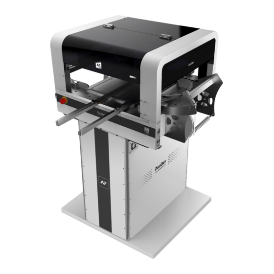
1. Brief Introduction 1.1. Product Introduction NeoDen4,the 4 generation pick and place machine of NeoDen Tech., was independently designed and developed with patents and CE certificate. This machine equipped with dual cameras, four heads, auto rails,electronic feeder,two conveyor ports, which achieves high accuracy,simple structure,stable performance and easy operation. -
Page 7: Structure Of Neoden 4
1.2. Structure of NeoDen 4 Each part mentioned above can be disassembled and tested. Please find more details on P20. ①:Placement head ②: Nozzle ③:Rails ④:Vibration feeder ⑤:On/Off button ⑥:Conveyor port ⑦:Multi-hole positioning board ⑧:Feed box ⑨:Peel box ⑩:Emergency button ⑪:Power switch... -
Page 8: Operation Flow Chart
2. Operation Flow Chart Flow chart Note Check the working environment Preparation whether it is safe or not Turn on The machine will start a 1-2 mins self-inspection after boot-up. It enters Initialization the operation page once finished. Operation page Please check detailed programming Edit tutorial in P10. -
Page 9: Procedure For Making A Programming File
3. Procedure for making a programming file See P10 1. PCB feed setting Edit the file See P11 2、Chip list Select Save file and See P 17 start 3.Feeder setting return Add a new file working 4.Panelized PCB first See P11 chip setting See P13 5.Mark point setting... -
Page 10: Edit On The Operation Interface
4. Edit on the Operation Interface 4.1. Edit on the Interface See below Fig.: Edit Interface 4.1.1. PCB Feeding Setting Function:Used to confirm the feeding place,first edit item in manual program Introduction of function keys: (1) Tray Fixed:Once select tray fixed,the setting items of board feeding will be closed.We only need use the positioning column to fix the board. -
Page 11: 3) Rail Multi
to finish the setting. Fig.2 Fig.3 (3) Multiple rail feed: This is only available for long board that can’t be handled once, such as LED strip. After finished one part of PCB, the rails will advance the board and handle the left part automatically. -
Page 12: 1) Single Pcb
relative spacing, in order to achieve the effect of the actual placing. Operation introduction (1) Single PCB: Only need to enter “1” in the row and column, some other useless function will turn grey. The “left bottom” is functional, which means the first PCB.Then you can press “align” to go to the screen of vision and get the coordinate of first component, see image 2-2. -
Page 13: 3) Pcb Angle Correction
After setup, click “create panelized list”, the data will be generated accordingly in the blank. (3)PCB angle correction: angle deviation of PCB board compare to rails (4)Bad board detection:used for find the bad PCB board and skip 4.1.3.PCB mark point setting Fig.3-1 Function: After completing setup of the mark points, with which the machine can locate the position of PCB and identify the set up mark points, so that the next step can be followed... -
Page 14: 3) Maunal
Fig.3-2 Import coordinate: according to the PCB schematic, we get the coordinate of mark and write down manually. Mark point information; Min-Max: Based on different size of mark point to find the correct position in case of any confusion. Light source: inner ring and outer ring. Use inner ring if the board holes work as fiducials , use outer ring if light-spots work as fiducials. -
Page 15: Chip List Setting
4.1.4.Chip list settings Function: to display the sequence, footprint and other information of components. There are two ways to add these information: manual programming and import mounting file. Operation: (1) Manual programming: firstly, check the box of manual programming. There is a sample line of the first component, please modify this line firstly. -
Page 16: 2) Import Pcb Bom File
to move (Visual field/Overall Workbench).Once clicked the “Save” item,the interface will automatic back to main page,then input the corresponding values(Designator refer to the location,Specification refer to the value of resistance,Footprint refer to the normal package info,I.e.0603,0805,1206,Etc.Angle value should be set according to the required direction on the PCB and polarity ,horizontal direction(0 or 180 degree),vertical direction(90 or -90 degree).The first component have been completely created after set all above values.The next step is click “New”item and will pop up one line(completely copy the previous line),then click “Align”... -
Page 17: Feeder Configuration
4.1.5.Feeder configuration (1) Feeders Arrangement:Left Feeders(Feeder20-48),Right Feeders(Feeder1-19),Special Feeders(Feeder49-58). There are two ways to setup feeders. ①Before installing tape&reels. Press “Allocate Chip to Feeder”, it will calculate how many different components according to Chip List, and automatically allocate them to each feeder in sequence. ②After installed tape&reel Click on each feeder, it will pop out a drop-down list with all components’specification, select one by one according to actual allocation. - Page 18 Feed-box information setting Function:Adjust the value for feeder and peel box Peel Strength:Support do adjustment according to different components’ required strength,default value 100 Feeding rate: It's the distance between two components. Feed strength:Adjust the feed strength by changing the value,default value 60 Feed test:After finishing above steps,can click this item to test the feed status Tray feeder information Function:Use to set the components’...
- Page 19 Feeder basic information Fig.5-1 Fig.5-2 Pick position X/Y:First have to lock the position of component on the feeder(See fig.5-2),once saved the modification, the XY data will automatically change to the ones after alignment. Pickup Angle:The initial default angle is 90 degrees, support to do modifying the value in order to change the mounting angels for wholly feeder if needed.
- Page 20 Nozzle Information Function:Function:Select corresponding nozzles according to actual demand. It will automatically assign to each feeder in order to meet the requirements of single head or multi heads working. Align:The nozzle will align to the component’s upside on corresponding feeders when click this item Height Test:After clicking this item,the nozzle will go down and check whether the pick height is ok.
-
Page 21: File Mounting
4.2. File Mounting 1.Method to mount one file: First select one file, click”mount”, then you will enter into one mounting page, above picture is an example of one file in mounting. (1) On the top-left corner shows mounting process, chip list---by the variation of blue line, you can track process of mounting constantly. -
Page 22: Manual Test
4.3. Manual Test Function: Used for testing the basic functions, connection between software and hardware is the mainly function, details about testing as below: 4.3.1.Placement head Choose nozzle 1, nozzle 2, nozzle 3, nozzle 4 to test separately Blow, after click this option, air will blow-off from selected nozzle Suck, after click this option, suction action will appear from selected nozzle Turn left&... -
Page 23: Rails Control
nozzle. Head move, after click this option, you will enter into”head move”page, click to move (Overall Workbench) you can test to move in a wide range. 4.3.2.Rail control Function, test rail PCB feeding,forward PCB feeding, backward PCB feeding and feeding speed 4.3.3.Hose control Function, test each function key Start button status, on the left side of machine, it has one start button, press this button the... -
Page 24: Feeder Test
Up Looking Camera Photograph, after click this option will take a picture Send PCB feeding command, after click this option, PCB will feed forward Buzzer,after click this option some sound will appear X Y step out recover&X Y Initialize, after click this, machine will recover to its original position and coordinates in system will initialize. - Page 25 As pic show, function description of button on right side Save configuration: click it for saving after modify the parameters Modify password: click it, put into the password, then finish change the fourth page which is also the System interface. Set up feeder ID: click and show as pic above.
-
Page 26: 1Feeder Configuration
Version upgrade: After receiving our new version file, you can upload it with clicking “version upgrade” to finish. ENGLISH:Change to the English version. 4.4.1.Feeder configuration As figure show: parameters setting for all feeders. First list on left side is feeder No. X,Y parameters is setting the feeder’s pick position. - Page 27 Save after setting well the pick position of the feeder. Same way as in the file. “Feed-box” setting It is used to set the feed-box ID. E.g., if you insert the feed-box 2 in the port 1, then it need to set the feed-box ID to be 2 “Peel Box”setting “Peel box”...
- Page 28 For example,the default port ID for Stack 33 is 33,if the port 33 is broken and want to change to port 34,can set in this item “Feed test” Once clicked this item,then the machine will start Feed test,feed one component and help check whether the feed is normal...
-
Page 29: Feed Setting
4.4.2. Feed setting Function:Used to setting values for all stacks Feed rate:The distance between two components,default value 4mm,for 0402,should set 2mm. Strength Setting:Motor torque of feed for the stack(Normally no need to change). Test:The machine will do feed test separate after clicking this item,peel box won’t work during above test Alignment:Click peel box,the motor idling several rings to do the initial position of the calibration. -
Page 30: Peel Configuration
4.4.3.Peel Configuration Function:Peel configuration as above figure show,used to set the values for all peel boxes Feed rate:Similar meaning in Feed box part,mean length of rotation each time Strength:Torque setting of Peel motor(Plastic tape will be difficult strip away in the case of being affected with damp, can adjust bigger values of motor torque here) Test:The machine will do peel test separate after clicking this item,feed box won’t work during above test... -
Page 31: System Setting
4.4.4. System setting Function: it is mainly for correction the position of suction nozzle.(Notice: In case change by mistake,we ‘ve locked it by password. It can be changed by clicking the button of Password change and then insert password. Strongly recommend operating it under our engineer’s guidance). - Page 32 Click the central point among four nozzles under the shot can set the central point. Another way is press CTRL button then click the mouse to make each nozzle to identify their own central point in the four quadrants. (Notice: Please click the LENS ROTATION before setting the suction nozzle, then PnP machine will collect nozzle’s 360 degree rotation photos to synthesize.
-
Page 33: First Trial And Testing
Move the nozzle to any place of PCB board, put one piece of carbon paper, then click REMAINS(MARK), placement head will rotate and leave a dot, after that click the button of Focus that dot and save,it will be done (show as photo above ). Trash box position: setting the position of dropping component, it depends. -
Page 34: Continuous Smt Production
completely — The nozzle was blocked — The nozzle is damaged or has a crack — The size issue of nozzle would cause air leakage or insufficient suction. — The air hose is blocked or has a leakage problem, and even the pump has an issue. Frequently throwing components. -
Page 35: Structure And Maintenance Instruction
5. Structure and maintenance instruction 5.1. Structure chart ⑴ ⑻ ⑺ ⑼ ⑵ ⑹ ⑽ ⑶ ⑸ ⑷ ⑾ 1-1 Side view 1-2 Front view ⑴ Peel-box ⑵ Tape&Reel holder ⑶ fixed support ⑷ Power switch ⑸ Emergency stop ⑹ Feed-box ⑺... -
Page 36: 1Peel Box
5.1.1.Peel-box Fix the peel-box Installation of peel-box... -
Page 37: Tape&Reel Holder
5.1.2.Tape&Reel holder 5.1.3.Fixation support... -
Page 38: Feed-Box
5.1.4.Feed-box ⑴ ⑵ ⑶ ⑷ 5.1.5.Vibration feeder... -
Page 39: Auto-Rails
5.1.6.Auto-rails Adjustment of auto-rails Fig.3 Fig.2 Fig.1 See(Fig.1):Loosen screws on A and B,then the left rail can be moved arbitrarily. See(Fig.2):Put PCB on the groove of rails and tighten and screws A and B once confirmed the width. See (Fig.3) :Once finished width adjustment, put the board into rails. Check the effect picture as below... -
Page 40: Nozzle
5.1.7.Nozzle The size of nozzle Please choose nozzles according to the shape and size of components. Table 1-1 Nozzle Model XN03 XN07 XN14 XN22 XN40 XN75 Illustration Inner 0.3mm 0.7mm 1.4mm 2.2mm 7.5mm diameter Reference of nozzle selection In order to assure placement accuracy, please select nozzles according to the shape and size of components. - Page 41 size size 0201 0.6*0.3 0402 1.0*0.5 0603 1.6*0.8 0805 2.0*1.2 1206 3.2*1.6 1210 3.2*2.5 1812 4.5*3.2 2010 5.0*2.5 4.0*2.5 4.0*3.3 6.6*5.6 SOT23 3*1.4 SOT89 4.5*2.5 SOT223 6.4*3.7 TO252 6.5*6.3...
-
Page 42: Maintenance
5.2. Maintenance 5.2.1.Take effective measures to reduce/ avoid malfunction 1. reinforce daily maintenance P&P machine is that high-accuracy device which requires a clean working environment with constant temperature and humidity, so it’s necessary to have a routine maintenance. 2. Requirements for operator (1)Operator should get a basic operator training,which should cover fully all the skills and knowledge needed to safely operate the type of pick and place machine. -
Page 43: 2Maintenance Of Device
5.2.2.Maintenance of device Check below points daily (1)Please check below before turn on the machine ①Temperature and humidity:temperature range 20℃~26℃, humidity range 45~70%. ②Working environment:please keep air fresh to avoid corrosive air in. ③Make sure there’s no obstacle on dual rails or the whole working area. ④Make sure camera lens is clean, no dirty things. -
Page 44: 3Placement Failure Analysis And Troubleshooting
5.2.3.Placement failure analysis and troubleshooting Placement failure analysis Whether Pick and Place machine can run normally or not, which will directly impact on production quality and volume. To make the machine run properly, we must fully understand the structure and characteristics of the machine, master every kinds of failure patterns of manifestation,reason and troubleshooting methods. -
Page 45: 4Related Issues During Solder Paste Printing Process
off and use cleaning needle to clean the nozzle Current nozzle size is not suit to component , change another one Surface uneven on the component, replace with a qualified one Component is sticking to the bottom tape; Burrs on tape hole stuck component; Component’s pin get stuck in the corner of the den;... -
Page 46: The Defects Of Solder Paste Printing, Reasons And Solutions
1.The using amount of solder paste should be uniform, good consistency. Solder paste graphics should be clear, try to avoid adhesion between adjacent graphics. Solder paste graphics and solder graphics should be consistent. 2.In general,keep unit area amount of solder paste about 0.8 mg/mm². For fine pitch components, should be 0.5 mg/mm²...