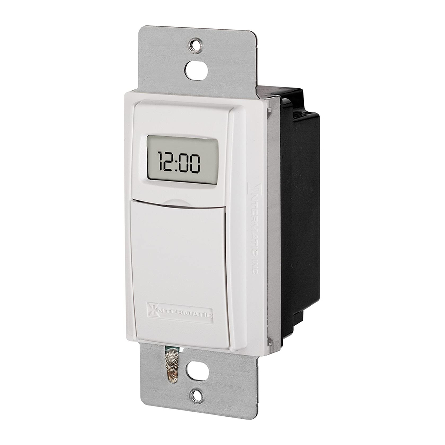
Intermatic ST01 Series Easy-Set Manual
In-wall timer with astro feature
Hide thumbs
Also See for ST01 Series:
- User manual ,
- Easy setting manual (2 pages) ,
- Installation and user manual (2 pages)
Advertisement
Available languages
Available languages
Quick Links
http://waterheatertimer.org/Programmable.html#st01
MODEL ST01 Series
Ratings:
• Resistive (heater): 15 A, 120-277 VAC
• Tungsten (incandescent): 15 A, 120 VAC; 6 A, 208-277 VAC
• Ballast (Fluorescent): 8 A, 120 VAC; 4 A, 208-277 VAC
• Motors: 1 HP, 120 VAC; 2 HP, 240 VAC
• DC Loads: 4 A, 12 VDC; 2 A, 28 VDC
Risk of Fire or Electric Shock
WARNING
•
Disconnect power at the circuit breaker(s) or disconnect switch(es) before
installing or servicing.
•
Installation and/or wiring must be in accordance with national and local
electrical code requirements.
•
Use COPPER conductors ONLY.
•
Do Not recharge, disassemble, heat above 212° F (100° C), crush, or incinerate
the non-replaceable Lithium battery. Keep Out of Reach of Children. Replace
only with Panasonic type CR2 or equivalent CR2 battery approved by
Underwriter's Laboratories (UL). Use of a different battery may present a risk of
fi re or explosion upon disposal of battery.
•
Do NOT use timer to control devices that could have dangerous consequences
due to inaccurate timing, such as: sun lamps, saunas, heaters, crock pots, etc.
NOTICE
•
Risk of timer damage due to leakage if weak battery is not replaced promptly.
•
Dispose of product per local regulations for disposal of Lithium batteries.
1-Before Installing Switch Timer, Install and Check Battery
Before installing the switch timer into the wall, make sure the supplied battery is installed
and working.
1. Open the access door to reveal the battery tray, located below the ON/OFF keypad.
2. If there is a pull tab at the battery tray, remove the tab to connect the installed
battery. Make sure battery tray is pushed fully into place. Proceed to Step 6.
3. If the battery was supplied loose, pry open the battery tray and remove it
from the timer.
4. Place the supplied "CR2" battery into the tray, observing + and - markings on tray.
5. Replace the battery tray into the switch timer.
6. The display will initialize itself then fl ash "12:00AM" in MANual mode.
7. Press the ON/OFF button. The switch timer should "click."
NOTE: If display doesn't fl ash "12:00am", the battery may be dead. Replace the battery
before installing the switch timer.
For new installations, it is recommended that you set up and program your timer
before installing it in your wall. This will make it easier to follow the instructions
while programming the timer.
Since the timer is battery-powered and does not need AC power to program, all
of your settings will be saved in the timer and ready to be used once the timer is
installed.
Installing the Switch Timer
1. Turn off power at the service panel by REMOVING FUSE or TURNING THE CIRCUIT
BREAKER OFF.
2. Remove the existing wall switch.
3. Trim building wires to 7/16" as shown.
If a Single Switch Setup.
A. Connect one of the two wires from the wall to the black wire from the switch
timer, using the twist connectors provided.
B. Connect the other wire from the wall to the blue wire from
the switch timer, using the twist connectors provided.
NOTE: The RED wire is not used in single-switch installa-
tions. Cap with a twist connector.
C. Connect the GREEN wire to the grounding screw in the
box. If a plastic box, connect to ground as supplied.
D. Make sure all twist connectors are tight.
If a 3-Way Switch Setup.
NOTE: The distance between switch timer and remote switch must not exceed 100 feet.
A. Locate the COMMON wire connected to fi rst
old switch. It might be attached to a different
colored screw, or fi nd markings on old switch.
B. Connect BLACK wire from switch timer to
COMMON wire, using a twist connector.
C. Connect the other two wires from the old
switch to the Blue and RED wires from the switch
timer.
D. Connect the GREEN wire to the grounding screw in the box. If a plastic box, connect to
ground as supplied.
E. Using diagram #1 below, identify and remove wire "C" from the "Common" terminal of
your existing remote switch.
DIAGRAM 1:
"COMMON" TERMINAL
LINE
WIRE "A"
TYPICAL
EXISTING
WIRE "B"
2-SWITCH
3-WAY
SETUP
MAIN SWITCH
F. Using diagram #2 below, remove and reconnect wires "B" and "C" to the
"Common" terminal of your remote switch, using the supplied piece of jumper
In-Wall Timer with Astro Feature
Easy-Set Guide
7/16"
BLACK WIRE
BLUE WIRE
RED WIRE
(capped, not connected)
RED WIRE
BLUE WIRE
WIRE FROM
"COMMON" OF
OLD SWITCH
BLACK WIRE
LOAD
WIRE "C"
NEUTRAL
3-WAY
REMOTE SWITCH
wire, if necessary. Follow diagram #3 below, if using a new single-pole remote
switch.
NOTE: For new construction or to replace a dimmer switch, a lighted switch, or
a 3-way switch without screw terminals, a single-pole switch can be used at the
remote location, as shown.
DIAGRAM 2:
LINE
2-SWITCH SETUP,
BLACK
TIMER INSTALL
TIMER
RE-USING EXISTING
REMOTE 3-WAY SWITCH
DIAGRAM 3:
LINE
2-SWITCH SETUP,
BLACK
TIMER INSTALL USING
TIMER
NEW SINGLE-POLE
REMOTE SWITCH
NOTE: If the building's wiring colors don't allow you to tell wire "A" from "B", just pick
one of the two wires and connect as if it is wire "B". After the installation is complete,
if the controlled light or device will not turn on properly, simply reverse wires "A" and
"B". See Steps J and K for how to check.
G. Tuck wires into the timer wall box leaving room for the timer.
H. Using screws provided, mount the switch timer into the wall box, then install the
wall plate.
I.
Install the remote 3-way switch in its box and install wall plate.
Turn the power back on at the service panel.
J. Make sure the switch timer displays "MAN" mode. Do the following test with the
remote switch in each of its 2 positions: Press the ON/OFF button on the switch
timer several times. Each time that you push the ON/OFF button, the switch timer
should '"click" and the controlled light or device (the "load") should turn on or off.
If so, proceed to Step K.
- If the timer clicks but the load does not operate, re-check your wiring and make sure
the load is functional.
- If the timer clicks but the load only operates when the remote switch is in one of its
2 positions, you need to turn off the power at the service panel, then reverse wires
"A" and "B". You can reverse wires "A" and "B" at the remote switch wall box, or you
can reverse wires "A" and "B" where they connect to the red and blue wires of the
switch timer. Then turn power back on at the service panel and repeat Step J.
K. Verify that the controlled load turns on or off each time that the remote switch is
operated. Your timer is now ready to be set.
To Clear the Timer
1. Press and hold down the ON/OFF button.
2. Using a paper clip or pen, press and release the RESET button, which is to the
lower right of the + button.
3. Continue holding ON/OFF until you see INIT on the screen.
4. Release ON/OFF.
5. Wait until you see 12:00 am in MANual mode.
Setting the Time and Date
1. Press MODE to display SETUP. - Press ON/OFF.
2. Press + or - to set your hour for the current time of day. - Press ON/OFF.
3. Press + or - to set your minutes for the current time of day. - Press ON/OFF.
4. Press + to advance the year if needed. - Press ON/OFF.
5. Press + or - to change the month. - Press ON/OFF.
6. Press + or - to change the date. - Press ON/OFF.
7. Press ON/OFF to choose DST (Daylight Saving Time)
• Press + to select Man if you do not observe DST, or
• Press + again to select Auto to automatically set for DST.
8. Press ON/OFF to choose zone.
9. Press + to select your zone. (Refer to map for
proper zone.
10. Press ON/OFF to review Dawn Time.
11. Press ON/OFF twice to review Dusk Time.
12. Press ON/OFF twice to save.
Programming Dusk ON/Dawn Off
1. Press MODE to display PGM.
2. Press ON/OFF three times to choose DUSK.
3. Press ON/OFF to choose the days you need, then press + to change days from
ALL, M-F, WeeKenD, or individual day.
4. Press ON/OFF to SAVE you work. - Press + to go to Program 2.
5. Press ON/OFF twice to display DAWN.
6. Press ON/OFF to choose the days you need, then press + to change days from
ALL, M-F, WeeKenD, or individual day.
7. Press ON/OFF to SAVE your work. - Press MODE to display AUTO.
Programming Dusk ON/Fixed Time OFF
1. Press MODE to display PGM. - Press ON/OFF three times to choose DUSK.
2. Press ON/OFF to choose the days you need, then press + to change days from
ALL, M-F, WeeKenD, or individual day.
3. Press ON/OFF to SAVE your work.
4. Press + to go to Program 2. - Press ON/OFF twice to display DAWN.
5. Press + until you get to 12:00 pm. - Press ON/OFF.
6. Press + or - to set the hour of the OFF time. - Press ON/OFF.
LOAD
NEUTRAL
WIRE "C"
BLUE
WIRE "B"
JUMPER
RED
WIRE "A"
"COMMON" TERMINAL
3-WAY
NOT USED
REMOTE SWITCH
LOAD
BLUE
WIRE "B"
WIRE "C"
JUMPER
RED
WIRE "A"
SINGLE-POLE REMOTE SWITCH
North
Center
South
Fig. 10
Fig. 8
NEUTRAL
North
Center
South
Advertisement

Related Manuals for Intermatic ST01 Series


Summary of Contents for Intermatic ST01 Series
- Page 1 In-Wall Timer with Astro Feature Easy-Set Guide MODEL ST01 Series Ratings: wire, if necessary. Follow diagram #3 below, if using a new single-pole remote switch. • Resistive (heater): 15 A, 120-277 VAC NOTE: For new construction or to replace a dimmer switch, a lighted switch, or •...
- Page 2 Pour de plus amples renseignements sur le programme et les détails de la garantie, se 8. Press + to change it to 12:00 pm. - Press ON/OFF. reporter aux instructions ou consulter : www.intermatic.com 9. Press + or - to set the hour for the OFF time. - Press ON/OFF.
- Page 3 Pour remettre la minuterie à zéro Activation au coucher du soleil/désactivation à heure fixe 1. Enfoncez et maintenez la touche d’activation ON/OFF. Appuyez sur MODE pour afficher PGM (programmation). 2. À l’aide d’un stylo ou d’un trombone, appuyez et relâchez la touche RESET, soit la Appuyez trois fois sur ON/OFF pour choisir coucher du soleil (DUSK).
- Page 4 13. Presione el botón ON/OFF para seleccionar la función DST (Tiempo de ahorro de CABLE NEGRO D. Asegúrese de que todos los conectores de torsión estén energía) apretados. • Presione + para seleccionar Man la función DST o Instalación de un interruptor de tres vías: •...