Quanser 3 DOF Hover User Manual
Hide thumbs
Also See for 3 DOF Hover:
- Laboratory manual (18 pages) ,
- Quick start manual (4 pages) ,
- Quick start manual (4 pages)
Table of Contents
Advertisement
Quick Links
Advertisement
Table of Contents

Related Manuals for Quanser 3 DOF Hover


Summary of Contents for Quanser 3 DOF Hover
- Page 1 Quanser 3 DOF Hover User Manual 3 DOF Hover Quanser Inc. 2013...
- Page 2 Fax: 1-905-940-3576 Printed in Markham, Ontario. For more information on the solutions Quanser Inc. offers, please visit the web site at: http://www.quanser.com This document and the software described in it are provided subject to a license agreement. Neither the software nor this document may be used or copied except as specified under the terms of that license agreement.
-
Page 3: Table Of Contents
CONTENTS Presentation System Description Components System Specifications System Setup Assembling the 3 DOF Hover Balancing the 3 DOF Hover Typical Connections Testing and Troubleshooting Motor Encoder Technical Support v 1.0 3 DOF HOVER User Manual... -
Page 4: Presentation
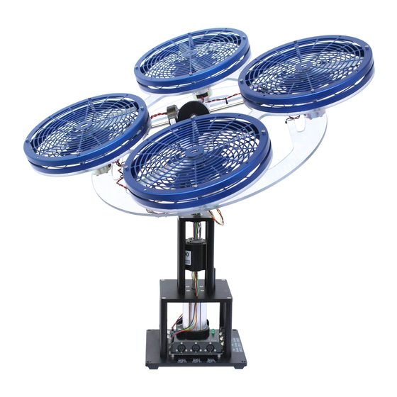
The Quanser 3 DOF Hover system consists of a frame with four propellers. The frame is mounted on a three degree of freedom pivot joint that enables the body to rotate about the roll, pitch and yaw axes. Each propeller generates a lift force and the lift forces are used to control the pitch and roll angles. -
Page 5: System Description
2.1.1 Quanser 3 DOF HoverOverall Components The components comprising the Quanser 3 DOF Hoversystem are labeled in Figure 2.1, Figure 2.2, and Figure 2.3, are described in Table 2.1. The motors, propeller assemblies, and encoders are described in more detail below. - Page 6 2.1.2 DC Motors (Components #2) The Quanser 3 DOF Hover has four DC motors: the front and back motors that mainly control the system about the pitch axis and the left and right motors that primarily move it about the roll axis.
-
Page 7: System Specifications
2.1.4 Encoders (Components #4 and #5) The Quanser 3 DOF Hover experiment has three encoders used to measure the angle of pitch, yaw, and roll axes. In quadrature mode, each encoder has a resolution of 8192 counts per revolution. Thus the effective position resolution is 0.0439 degrees about the yaw, pitch, and roll axes. - Page 8 Length of metal shaft rotating about yaw axis 0.280 shaf t Moment of inertia of metal shaft about yaw axis end 0.0039 kg-m shaf t point Table 2.4: Various 3 DOF Hover mass, length, and inertia parameters 3 DOF HOVER User Manual...
-
Page 9: System Setup
Follow these steps to setup the 3 DOF Hover system: 1. Place the base of the 3 DOF Hover, Component # 11 shown in Figure 2.1, on a table or on the floor. 2. Assemble the body to the main base by aligning the pitch/roll encoder frame, i.e., the yoke shown in Figure 2.2 as Component #6, with the top of the base and tighten the thumb screws. - Page 10 Note: Your configuration may be different. For instance, you may have a DAQ with more channels than the one presented in Figure 3.1 or have four single-channel amplifiers that do not require any Emergency Stop (in which case, you would omit connection #12). Figure 3.1: Typical connections of the 3 DOF Hover Experiment 3 DOF HOVER User Manual...
- Page 11 Stop switch is connected, the am- plifier can only be enabled if the red knob is in the released position. Table 3.1: Quanser 3 DOF Hover system wiring summary 3.3.1 Wiring Details Follow these steps to connect the Quanser 3 DOF Hoversystem: 1.
- Page 12 3.1. 6. Connect another 4-pin-DIN to 6-pin-DIN cable from the Amplifier 1 To Load (3x Amplifier Command) connector, to the Yaw Motor (D/A 1) connector on the Quanser 3 DOF Hoverplant. This is illustrated by connection #4 in Figure 3.1.
-
Page 13: Testing And Troubleshooting
This section describes some functional tests to determine if your system is operating normally. It is assumed that the Quanser 3 DOF Hoveris connected as described in Section 3.3. To carry out these tests, it is preferable if the user can use a software such as QUARC LabVIEW™... -
Page 14: Technical Support
2048 counts. Make sure the details of the data-acquisition system being used is known. The counters on the Quanser DAQ boards measure in quadrature and therefore a total of four times the number of encoder lines per rotation, e.g., a 2048-line encoder results in 8192 integer counts for every full rotation. - Page 15 REFERENCES [1] Pittman. LO-COG DC Servo Motors 8000, 9000, 14000, 2010. v 1.0 3 DOF HOVER User Manual...