Table of Contents
Advertisement
Con
Con tr tr tr tr tr actor Series
Con
Con
Con
Some models may be exported under the name Amcron .
Note on Preliminary Status: Crown continues to stand behind its products as guaranteed to meet or exceed
published specifications. However, at the time of this manual's publication, not all of the CH and CL models
were in production. Guaranteed specifications for all CH and CL models will be issued at the time of product
release.
© 2000 by Crown International, Inc., P.O. Box 1000, Elkhart, IN 46515-1000 U.S.A. Telephone: 219-294-8000.
Fax: 219-294-8329. Trademark Notice: Amcron
International, Inc. Other trademarks are the property of their respective owners.
Obtaining Other Language Versions:
To obtain information in another language about the use of this product, please contact your local Crown Distribu-
tor. If you need assistance locating your local distributor, please contact Crown International at 219-294-8200.
actor Series
actor Series
actor Series
actor Series
Models:
CH1, CH2, CH4
CL1, CL2, CL4
®
and Crown
®
®
are registered trademarks of Crown
130808-1
5/00
Advertisement
Table of Contents

Related Manuals for Crown Contractor Series


Summary of Contents for Crown Contractor Series
- Page 1 International, Inc. Other trademarks are the property of their respective owners. Obtaining Other Language Versions: To obtain information in another language about the use of this product, please contact your local Crown Distribu- tor. If you need assistance locating your local distributor, please contact Crown International at 219-294-8200.
- Page 2 Contractor Series Power Amplifiers This page intentionally left blank Page 2 Reference Manual...
- Page 3 Contractor Series Power Amplifiers Important Safety Instructions 1) Read these instructions. 2) Keep these instructions. 3) Heed all warnings. 4) Follow all instructions. 5) Do not use this apparatus near water. 6) Clean only with a dry cloth. 7) Do not block any ventilation openings. Install in ac- cordance with the manufacturer’s instructions.
- Page 4 ITEMS EXCLUDED FROM THIS CROWN WARRANTY Note: If your unit bears the name “Amcron,” please substitute it for the This Crown Warranty is in effect only for failure of a new Crown product which name “Crown” in this warranty. occurred within the Warranty Period. It does not cover any product which has...
- Page 5 Nor does it cover every possible situation which may arise during installation, operation or mainte- nance. If your unit bears the name “Amcron, ” please substitute it for the name “Crown” in this manual. If you need special assistance beyond the scope of this manual, please contact our Technical Support Group.
-
Page 6: Table Of Contents
® (CH4 and CL4 Only) ..........19 5.2 Switching Power Supply with PFC (CH4 and CL4 Only) ..19 5.3 Crown SST Modules ............20 5.3.1 SST-MX Crossover ............ 20 5.3.2 SST-SX Crossover ............. 20 5.3.3 SST-SBSC Module ............ 21 5.4 Fault Monitoring .............. - Page 7 This page intentionally left blank ..................2 Figure 1.1 Contractor Series Amplifiers ................8 Figure 2.1 Contractor Series Front Panel Controls and Indicators ......... 10 Figure 2.2 CH1 & CH2 Back Panel Controls and Connectors ........10 Figure 2.3 CH4 Back Panel Controls and Connectors ........... 11 Figure 2.4 CL1 &...
-
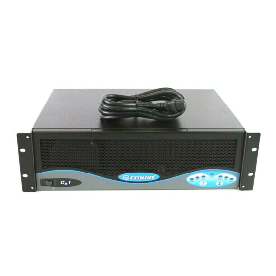
Page 8: Contractor Series
Contractor Series Power Amplifiers Figure 1.1 Contractor Series Amplifiers Page 8 Reference Manual... -
Page 9: Welcome
Contractor Series amplifier should it fail at any non-operational. time during the original 3-year warranty period follow- An RJ11 connector allows external circuits to monitor the ing the date of original purchase. -
Page 10: Controls, Indicators And Connectors
Contractor Series Power Amplifiers 2 Controls, Indicators and Connectors Figure 2.1 Contractor Series Front Panel Controls and Indicators Figure 2.2 CH1 & CH2 Back Panel Controls and Connectors Page 10 Reference Manual... -
Page 11: Figure 2.3 Ch4 Back Panel Controls And Connectors
Contractor Series Power Amplifiers Figure 2.3 CH4 Back Panel Controls and Connectors Figure 2.4 CL1 & CL2 Back Panel Controls and Connectors Figure 2.5 CL4 Back Panel Controls and Connectors Reference Manual Page 11... -
Page 12: Installation
All Contractor Series amplifiers are in- As you can see in Figure 3.1, Contractor Series amplifi- tended for rack mount installations using a commer- ers vary in their depth demensions. Figure 3.1 shows cial 19-inch (48.3-cm) EIA rack standard metal... -
Page 13: Input Wiring
Contractor Series Power Amplifiers Contractor Series amplifiers can be configured for ei- lected, the 70V and 100V connections are inactive, with ther Stereo (dual channel) or Bridge (single mono chan- no audio present at those Output Terminals. nel) modes of operation. To switch your amplifier Figures 3.4 through 3.11 on the following pages show... -
Page 14: Figure 3.4 Ch1 & Ch2 Wiring For Stereo Mode
Contractor Series Power Amplifiers Figure 3.4 CH1 & CH2 Wiring for Stereo Mode Figure 3.5 CH1 & CH2 Wiring for 140V Bridge Mode Page 14 Reference Manual... -
Page 15: Figure 3.6 Ch4 Wiring For Stereo Mode
Contractor Series Power Amplifiers Figure 3.6 CH4 Wiring for Stereo Mode Figure 3.7 CH4 Wiring for Bridge Mode Reference Manual Page 15... -
Page 16: Figure 3.8 Cl1 & Cl2 Wiring For Stereo Mode
Contractor Series Power Amplifiers Figure 3.8 CL1 & CL2 Wiring for Stereo Mode Figure 3.9 CL1 & CL2 Wiring for Bridge Mode Page 16 Reference Manual... -
Page 17: Figure 3.10 Cl4 Wiring For Stereo Mode
Contractor Series Power Amplifiers Figure 3.10 CL4 Wiring for Stereo Mode Figure 3.11 CL4 Wiring for Bridge Mode Reference Manual Page 17... -
Page 18: Operation
Contractor Series Power Amplifiers 4 Operation 4.3 Indicators The front panel of a Contractor Series amplifier has sev- 4.1 Precautions eral helpful indicators (Figure 4.1). The blue Power in- Contractor Series amplifiers are protected from internal dicator shows that the amplifier has been turned on and external faults, but you should still take the follow- and has power. -
Page 19: Controls
(Section 3) , or consult your active) load impedances, even under extreme system installer. conditions. In fact, Crown BCA amps have far out-per- When Bridge mode is selected, only the Channel 1 formed competitive amplifiers in tests where the ampli-... -
Page 20: Crown Sst Modules
Crown Service Center. For information on wiring and configuration of amplifi- ers equipped with an optional Crown SST crossover module, please refer to the applicable SST Crossover Reference Manual. -
Page 21: Sst-Sbsc Module
5.4 Fault Monitoring The Fault (RJ11) jack is located on the back of your Contractor Series amplifier. It gives you an easy way to remotely monitor the amplifier’s fault status. See Sec- tion 9.5 for details about how to connect external cir- cuits to the Fault jack. -
Page 22: Principles Of Operation
To obtain a with a –3 dB rolloff at 70 Hz. This provides a measure of constant voltage computer, call Crown and ask for lit- protection to step-down transformers used in distrib- erature. -
Page 23: Figure 6.2 Cl1 & Cl2 Circuit Block Diagram
Contractor Series Power Amplifiers operation, but allows the devices to provide high bursts disconnects the load via the output relay, removing any of peak power when needed. This amplifier output to- output current and further speeding a cool-down cycle. pology offers a good combination of low quiescent am-... -
Page 24: Ch4 And Cl4
Contractor Series Power Amplifiers 6.2 CH4 and CL4 ing signals that are too high. Without the 32-kHz filter, the modulator would be unable to process signals that 6.2.1 Audio Signal Path are too high and the output filter would not yield the For the sake of simplicity, only channel one of the audio proper frequency response behavior. -
Page 25: Figure 6.4 Cl4 Circuit Block Diagram
Contractor Series Power Amplifiers Pulse Width Modulated (PWM) string of pulses at 250 The turn-on delay circuitry functions to keep the modu- kHz that vary in width depending on the level of the lators turned off (which keeps the outputs from switch- input signal. -
Page 26: Power Supply Operation
Contractor Series Power Amplifiers An RJ11 modular jack is mounted on the back panel. the line voltage. This reduces the load on the power Pins 2 and 5 are connected to an opto-isolator that is companies and also allows the amplifier to pull more always in a low-resistance state whenever the unit is on peak power from the power source (the outlet). -
Page 27: Specifications
Contractor Series Power Amplifiers 7 Specifications CL4, 34 dB (4/8 ohm). Note: All measurements apply to all models of CH and CL series amplifiers in stereo mode with 8-ohm loads and an input sensi- AC Line Requirements: tivity of 26-dB gain, 1-kHz at rated power unless other otherwise Note: North American CH 1, CL 1, CH 2 and CL 2 specified. - Page 28 Contractor Series Power Amplifiers Crosstalk, 20 Hz to 20 kHz: Better than 50 dB below Input Stage: Input is electronically balanced and rated power. employs precision 1% resistors. Common Mode Rejection (CMR): Better than 70 dB Input Impedance: Nominally 20 k ohms, balanced.
-
Page 29: Figure 7.1 Contractor Series Output Power
For shipping weight, add 6 pounds (2.7 kg) to each CH 1: 40.6 pounds (18.4 kg); amp. CH 2: 48.3 pounds (21.9 kg); Figure 7.1 Contractor Series Output Power Figure 7.2 CH1 & CH2 Frequency Response Figure 7.3 CL1 & CL2 Frequency Response Reference Manual... -
Page 30: Figure 7.4 Ch4 & Cl4 Frequency Response
Contractor Series Power Amplifiers Figure 7.4 CH4 & CL4 Frequency Response Figure 7.5 CH1, CH2, CL1 & CL2 Damping Factor Figure 7.6 CH4 & CL4 Damping Factor Page 30 Reference Manual... -
Page 31: Figure 7.7 Ch1, Ch2, Cl1 & Cl2 Output Impedance
Contractor Series Power Amplifiers Figure 7.7 CH1, CH2, CL1 & CL2 Output Impedance Figure 7.8 CH4 & CL4 Output Impedance Reference Manual Page 31... -
Page 32: Ac Power Draw And Thermal Dissipation
AC mains The value used for Amplifier Efficiency is 0.65 for CH1, by Contractor Series amplifiers and the amount of heat CH2, CL1 and CL2 models, and 0.77 for CH4 and CL4 produced under various conditions. -
Page 33: Figure 8.2 Ch2 Power Draw, Current Draw And Thermal Dissipation
Contractor Series Power Amplifiers Figure 8.2 CH2 Power Draw, Current Draw and Thermal Dissipation at Various Duty Cycles Figure 8.3 CH4 Power Draw, Current Draw and Thermal Dissipation at Various Duty Cycles Figure 8.4 CL1 Power Draw, Current Draw and Thermal Dissipation at Various Duty Cycles... -
Page 34: Figure 8.5 Cl2 Power Draw, Current Draw And Thermal Dissipation
Contractor Series Power Amplifiers Figure 8.5 CL2 Power Draw, Current Draw and Thermal Dissipation at Various Duty Cycles Figure 8.6 CL4 Power Draw, Current Draw and Thermal Dissipation at Various Duty Cycles Page 34 Reference Manual... -
Page 35: Installation Helps
(Figure 9.1, Option 2). The air flow requirement for a Contractor Series ampli- fier depends on many things, but the most important factor is average output power. -
Page 36: Solving Input Problems
Contractor Series Power Amplifiers one leg at ground potential, while the second leg is in Figure 9.6 shows some capacitor values and how “hot.” Unbalanced line is less expensive, but is much they affect frequency response. Use only low-leakage more susceptible to noise, and is not usually used in capacitors. -
Page 37: More About Output Modes
A, B, and C shown in Figure 9.7. will depend on the Stereo/Bridge mode you select, as well as the model of Contractor Series amplifier used. Another problem to avoid is hum. The two most com- CH Series models are rated to drive loads from 4 to 8... -
Page 38: Output Wiring
10,000 systems. If you will be using Bridge mode for 140-volt 5,000 or 200-volt output, you may need to cross-reference the ratings of the step-down transformer taps with Crown’s 2,000 constant voltage computer (see Section 5.6). ANNEALED 8000... -
Page 39: Solving Output Problems
1. Bundle together each pair of loudspeaker conductors 9.4.2 Additional Load Protection when using long cable runs or when different amplifiers Contractor Series amplifiers can generate enormous use a common cable tray or jacket. (Do NOT bundle power output. Using 4/8 ohm output, if your loudspeak- wires from different amplifiers.) This reduces the... -
Page 40: Fault Circuit Wiring
Figure 9.12. * The mating connector for the RJ11 Fault jack contains 4 contact pins in a 6-slot case, as shown. For additional information please contact your local dealer or Crown Technical Support. Page 40 Reference Manual... -
Page 41: Applications
The following system examples show the flexible con- the 70V distributed method. Taking advantage of the figuration capabilities of the Contractor Series, as well flexible output options with the CH Series amplifiers, as how combinations of CH and CL Series amplifiers... -
Page 42: House Of Worship
Contractor Series Power Amplifiers 10.2 House of Worship The CL2 is used in Stereo mode. One channel will drive multiple delay speakers in a balcony. The other channel CH1, CL2 and CL4 amplifiers are used in the house of will drive multiple stage monitors. The low impedance worship example, shown in Figure10.2. -
Page 43: Service
Remember to transport your unit in the original factory to transport the unit. pack. If you have any questions, please call or write the Crown 11.2 North American Service Technical Support Group. Service may be obtained in one of two ways: from an authorized service center or from the factory. - Page 44 Crown Factory Service Information Shipping Address: Crown International, Inc., Factory Service, Plant 2 SW, 1718 W. Mishawaka Rd., Elkhart, IN 46517 Phone: 1-800-342-6939 or 1-219-294-8200 Fax: 1-219-294-8124 Owner’s Name: _________________________________________________________________________ Shipping Address: ______________________________________________________________________ Phone Number: _____________________________ Fax Number: _____________________________ Model: ________________________ Serial Number: ______________ Purchase Date: ___________ NATURE OF PROBLEM (Be sure to describe the conditions that existed when the problem occurred and what attempts were made to correct it.)