Samson 3374 Series Mounting And Operating Instructions
Hide thumbs
Also See for 3374 Series:
- Mounting and operating instructions (84 pages) ,
- Mounting and operation instructions (68 pages) ,
- Mounting and operating instructions (104 pages)

Related Manuals for Samson 3374 Series


Summary of Contents for Samson 3374 Series
- Page 1 EB 8331-4 EN Translation of original instructions Type 3374 Electric Actuator Version with positioner, revision 3 Firmware version 3.12 Edition January 2020...
- Page 2 Note on these mounting and operating instructions These mounting and operating instructions assist you in mounting and operating the device safely. The instructions are binding for handling SAMSON devices. The images shown in these instructions are for illustration purposes only. The actual product may vary.
-
Page 3: Table Of Contents
Contents Safety instructions and measures ..............1-1 Notes on possible severe personal injury ............1-4 Notes on possible personal injury ..............1-5 Notes on possible property damage .............1-6 Markings on the device ................2-1 Nameplate ....................2-1 Firmware ....................2-2 Design and principle of operation ...............3-1 Fail-safe action ...................3-1 Communication ..................3-2 Versions .....................3-2... - Page 4 Contents 6.1.3 Keys on version with three-key operation ............6-4 Start-up and configuration ................7-1 Initializing the actuator ................7-1 7.2 Configuring the actuator ................7-2 7.2.1 Fast configuration level ................7-4 Selecting the application ................7-5 Adjusting the limit contacts ................7-8 Setting up communication ................7-10 7.5.1 Serial interface ..................7-10 7.5.2 Modbus RTU module .................7-10 Operation ....................8-1...
- Page 5 Removal ....................12-1 12.1 Construction with integrated yoke ...............12-1 12.2 Construction with ring nut ................12-2 Repairs ....................13-1 13.1 Returning the actuator to SAMSON ............13-1 Disposal ....................14-1 Certificates ....................15-1 Annex A (configuration instructions) ............16-1 16.1 Key number ....................16-1 16.2 Input signal ....................16-2 16.3...
- Page 6 Contents EB 8331-4 EN...
-
Page 7: Safety Instructions And Measures
SAMSON does not assume any liability for damage resulting from the failure to use the de- vice for its intended purpose or for damage caused by external forces or any other external factors. - Page 8 Î Check with the plant operator for details on further protective equipment. Revisions and other modifications Revisions, conversions or other modifications of the product are not authorized by SAMSON. They are performed at the user's own risk and may lead to safety hazards, for example. Fur- thermore, the product may no longer meet the requirements for its intended use.
- Page 9 Î For wiring, maintenance and repair, observe the relevant safety regulations. Referenced documentation The following documents apply in addition to these mounting and operating instructions: − Mounting and operating instructions of the valve on which the electric actuator is mount- ed, e.g. for SAMSON valves: u EB 5861 for Type 3260 Three-way Valve u EB 5868 for Type 3213 and Type 3214 Globe Valves u EB 8012 for Type 3241 Globe Valve, ANSI and JIS version u EB 8015 for Type 3241 Globe Valve, DIN version...
-
Page 10: Notes On Possible Severe Personal Injury
Safety instructions and measures 1.1 Notes on possible severe personal injury DANGER Risk of fatal injury due to electric shock. Î Before connecting wiring, performing any work on the device or opening the de- vice, disconnect the supply voltage and protect it against unintentional reconnec- tion. Î Only use power interruption devices that can be protected against unintentional re- connection of the power supply. -
Page 11: Notes On Possible Personal Injury
Safety instructions and measures 1.2 Notes on possible personal injury WARNING Crush hazard arising from moving parts. The electric actuator contains moving parts (actuator and plug stems), which can injure hands or fingers if inserted into the actuator. Î Do not insert hands or finger into the yoke while the valve is in operation. Î Disconnect the supply voltage before performing any work on the control valve. Î... -
Page 12: Notes On Possible Property Damage
1.3 Notes on possible property damage NOTICE Risk of damage to the electric actuator due to the supply voltage exceeding the per- missible tolerances. The Type 3374 Electric Actuator is designed for use according to regulations for low-voltage installations. Î Observe the permissible tolerances of the supply voltage. Risk of actuator damage due to excessively high tightening torques. Observe the specified torques when tightening the mounting parts of Type 3374 Electric Actuators. -
Page 13: Markings On The Device
Serial no. Digital Positioner Firmware: 0(4) ... 20 mA DC; Ri = 50 0(2) ... 10 V DC; Ri = 20 k 0062 SAMSON AG, Germany Made in Germany 1 Type 12 Limit contacts 2 Configuration ID 3 Serial number Mechanical limit contacts 4 Supply voltage; power line frequency... -
Page 14: Firmware
Markings on the device 2.2 Firmware Firmware revisions 3.10 3.11 (internal revisions) 3.11 3.12 Baud rate 38400 is no longer available for Modbus. Communication parameters can only be changed after the key number has been entered. Special version with three-key operation is available. The actuator version with three-key operation allows the set point to be changed and dis- played on the start screen in "PID controller"... -
Page 15: Design And Principle Of Operation
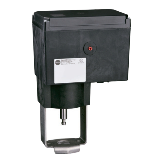
3 Design and principle of oper- ation The Type 3374 Electric Actuator is used in industrial plants as well as in heating, venti- lation and air-conditioning systems. The actuator is a linear actuator. It is suitable for form-fit attachment to various SAMSON valve series, depending on the version with or without fail-safe action. The Type 3374 Actuator is optionally avail- able with either integrated yoke (form A, see Fig. 3-1) or using an M30x1.5 ring nut (form B, see Fig. 3-2) including the neces-... -
Page 16: Communication
> Service & ation (TÜV) according to DIN EN 14597 in Support > Downloads > TROVIS-VIEW. combination with various SAMSON valves. Further information on TROVIS-VIEW (e.g. The register number is available on request. system requirements) is available on our website and in the Data Sheet u T 6661 as 3.2 Communication... -
Page 17: Additional Equipment
Design and principle of operation 3.4 Additional equipment Mechanical limit contacts The two mechanical limit contacts consist of two changeover switches. Their switching po- sitions are changed independently from one another by continuously adjustable cam disks. The floating contacts can be used as either make or break contacts to influence the tasks of control equipment. The installation and adjustment of the me- chanical limit contacts is described in the 'In- stallation' section. - Page 18 Design and principle of operation − Triggered when the position exceeds the switching point: The limit contact is activated when the actuator stem position moves beyond the switching point. The limit contact is deactivated when the ac- tuator stem moves below the switching point plus hysteresis.
- Page 19 Design and principle of operation Rotary pushbutton Display Serial interface Terminals Actuating shaft for mechanical manual override Terminal board for limit contacts Fig. 3-4: Operating controls (with housing cover removed) EB 8331-4 EN...
-
Page 20: Technical Data
Thrust in kN (standard version · Version with faster motor) Extends 2.5 · 1.25 2.5 · 1.25 2.5 · 1.25 Retracts 2.5 · 1.25 2.5 · 1.25 2.5 · 1.25 Weight [kg] Approx. For attachment to SAMSON Series V2001 Valves (DN 15 to 80) and to SAMSON Type 3260 (DN 65 to 150) and Type 3214 Valves (DN 65 to 100) For attachment to SAMSON Series 240 Valves and to SAMSON Type 3214 Valve (DN 125 to 250) Normal speed level (Code c64 = NORM) Fast speed level (Code c64 = FAST) EB 8331-4 EN... - Page 21 Upon fail-safe action 12 · 1.25 12 · 1.25 12 · 1.25 12 · 1.25 Thrust in kN Extends Retracts Nominal thrust of safety spring Weight [kg] Approx. For attachment to SAMSON Series V2001 Valves (DN 15 to 80) and to SAMSON Type 3260 (DN 65 to 150) and Type 3214 Valves (DN 65 to 100) For attachment to SAMSON Series 240 Valves Normal speed level (Code c64 = NORM) Fast speed level (Code c64 = FAST) EB 8331-4 EN...
- Page 22 Design and principle of operation Table 3-3: Common data Digital positioner Input signal Current input 0/4 to 20 mA, adjustable · R = 50 Ω Voltage input 0/2 to 10 V, adjustable · R = 20 kΩ Pt 1000 input Measuring range: –50 to 150 °C, 300 µA Binary input By jumpering the terminals, not galvanically isolated Position feedback Current 0/4 to 20 mA, adjustable · Error message 24 mA Resolution 1000 steps or 0.02 mA Load Max. 200 Ω Voltage 0/2 to 10 V, adjustable · Error message 12 V Resolution 1000 steps or 0.01 V Load Min. 5 kΩ Binary input Open-circuit voltage: 10 V; short-circuit current: 5 mA By jumpering the terminals, not galvanically isolated...
- Page 23 Design and principle of operation Device safety Degree of protection acc. to EN 60529 IP 54 with cable ducts IP 65 with cable glands (can be retrofitted) 1) Suspended mounting not permitted according to EN 60664 Class of protection II according to EN 61140 Device safety II according to EN 61010-1 Noise immunity According to EN 61000-6-2 and EN 61326-1 Noise emission According to EN 61000-6-3 and EN 61326-1 Conformity Permissible temperatures Ambient 5 to 60 °C Storage –25 to +70 °C Ambient conditions Humidity 5 to 95 % relative humidity, no dew formation Additional equipment...
-
Page 24: Dimensions In Mm
Design and principle of operation 3.6 Dimensions in mm Type 3374-10/-11/-21/-31 When the actuator stem is fully extended Type 3374 Dimension h Fig. 3-5: Dimensions (in mm) of Type 3374, construction with integrated yoke (form B) 3-10 EB 8331-4 EN... - Page 25 Design and principle of operation Types 3374-15/-26/-36 When the actuator stem is fully extended Type 3374 Dimension h Dimension h Fig. 3-6: Dimensions (in mm) of Type 3374, construction with ring nut (form A) EB 8331-4 EN 3-11...
- Page 26 3-12 EB 8331-4 EN...
-
Page 27: Shipment And On-Site Transport
M30x1.5 ring nut 2. Check the shipment for transportation Fig. 4-1: Scope of delivery damage. Report any damage to SAMSON and the forwarding agent (refer to delivery note). 4.3 Transporting the actuator 4.2 Removing the packaging − Protect the actuator against external in- fluences (e.g. impact). -
Page 28: Storing The Actuator
NOTICE Risk of electric actuator damage due to improper storage. Î Observe the storage instructions. Î Avoid long storage times. Î Contact SAMSON in case of different storage conditions or longer storage times. Note We recommend regularly checking the electric actuator and the prevailing storage conditions during long storage periods. -
Page 29: Installation
Installation 5 Installation The work described in this section is only to be performed by personnel appropriately quali- fied to carry out such tasks. 5.1 Installation conditions Work position If not described otherwise in the valve documentation, the work position for the control valve is the front view looking onto the operating controls. Mounting orientation The control valve can be installed in the pipeline in any desired position. However, a sus- pended mounting position of the actuator is not permissible (see Fig. 5-1). -
Page 30: Mounting The Actuator
Installation 5.3 Mounting the actuator 7. When the plug stem (5) fits closely onto the actuator stem (3), attach both stem connector clamps (4) and fasten with 5.3.1 Construction with screws. integrated yoke (form B) Attachment Types 3374-10/-11/-21/-31 − Series V2001 Valves (DN 15 to 80) Connection with yoke (form B) − Type 3260 (DN 65 to 150) Attachment to Series V2001 Valves, Type 3260 (DN 65 to 150), − Type 3214 (DN 65 to 100) Type 3214 (DN 65 to 100) -
Page 31: Construction With Ring Nut (Form A)
Installation 5.3.2 Construction with ring Tightening torque 150 Nm nut (form A) 6. Move the actuator stem (3) to the end position (valve closed) as described in Attachment to Series 240 Valves the 'Operation' section. Î Refer to Fig. 5-5. 7. Align travel indicator scale (10) with the 1. - Page 32 Installation Attachment to Type 3214 Valve (DN 125 to 250) Type 3374-15 Î Refer to Fig. 5-7. Connection with ring nut (form A) Attachment to Type 3214 Valve (DN 125 to 1. Retract the actuator stem using the manu- 250) al override (see the 'Operation' section). Actuating shaft Fig. 5-6: Actuating shaft for manual override (actuator for attachment with ring nut) 2.
-
Page 33: Retrofitting Limit Contacts
Installation 5.4 Retrofitting limit contacts NOTICE Î See Fig. 5-8 to Fig. 5-10. Risk of damage to the connecting cable due to incorrect handling. Î Actuator version with three-key opera- DANGER tion: make sure that the connecting cable Risk of fatal injury due to electric shock. between the housing cover and actuator Î... - Page 34 Installation addition, the adjustment gears (18) must engage properly in the corresponding gears of the contact cam unit (21). 8. Secure the contact cam unit (21) and in- termediate gear (1) with the serrated ring (3); push down the serrated ring as far as it will go. 9. Position the terminal board (17) at the base of the support at a 45° angle (ap- prox.) with the switches pointing towards Actuator stem re-...
- Page 35 Installation State on delivery: Intermediate gear Spindle (11) with Spindle gear serrated ring and shim Serrated ring Tension spring Spacer Spindle Actuator board Bearing sleeve Terminal board Adjustment gear Contact cam unit Fig. 5-10: Installing the limit contacts EB 8331-4 EN...
-
Page 36: Retrofitting Electronic Limit Contacts
Installation 5.5 Retrofitting electronic limit 3. Position the terminal board (17, see Fig. 5-5) at the base of the support at a contacts 45° angle (approx.) with the relay point- ing towards the edge of the intermediate DANGER board. Swivel the upper end of the termi- Risk of fatal injury due to electric shock. nal board until the board is properly en- Î... -
Page 37: Connecting The Wiring
Installation Î The pins must be guided from the top in- NOTICE to the socket on the board. Risk of actuator malfunction through the 5. Perform the wiring as described in the removal of the potentiometer gear. 'Installation' section. The actuator is ready to use in the delivered 6. - Page 38 Installation Note The function of the inputs depend on how the actuator is configured: inputs that have not been configured do not have any effect. Table 5-1: Cables and stranded wires that can be used Cable Cross section Single-wire H05(07) V-U 0.2 to 1.5 mm² Fine-wire H05(07) V-K 0.2 to 1.5 mm²...
- Page 39 Installation 0/4 to 20 mA – Position feedback 0/2 to 10 V – Inputs 1 to 4 – (see Fig. 5-12 to Fig. 5-17 for assignment) – – – Binary output Supply voltage (depending on version 24 V AC and DC; 85 to 264 V AC) 42 44 41 52 54 51 Options: Mechanical limit contacts Electronic limit contacts 42 44 41 52 54 51 42 44 41 52 54 51 RS-485 interface with 42 44 41 52 54 51 RS-485 interface...
- Page 40 Installation Application: Positioner (POSI) 0(4) ... 20 mA – 0(2) ... 10 V – – Binary signal Î Wire the input free of voltage. – Fig. 5-12: Terminal assignment for 'Positioner' application Application: PID controller (PID) 0(4) ... 20 mA – 0(2) ... 10 V –...
- Page 41 Installation Application: PID controller (PID), temperature control Pt 1000 (readout only possible using Modbus) – Pt 1000 (readout only possible using Modbus) – (controlled variable) Pt 1000 – Binary signal Î Wire the input free of voltage. – Fig. 5-14: Terminal assignment for 'PID controller' application · Temperature control Application: Two-step mode (2STP) – –...
- Page 42 Installation Application: Three-step mode (3STP) Three-wire connection: Four-wire connection: – – – – – Retracts – – Extends Binary signal – – Binary signal Î Wire all the inputs free of voltage. Fig. 5-16: Terminal assignment for 'Three-step mode' application Application: Temperature closed-loop control upon input signal failure (POSF) 0(4) ...
-
Page 43: Connection For Special Version With Three-Key Operation
Installation 5.7.2 Connection for special version with three-key operation Perform electrical connection for the special version of Type 3374 with three-key opera- tion as follows: Î Refer to Fig. 5-18. 1. Unthread the four fastening screws of the housing cover. Lift off the housing cover. Î Make sure the connecting cables (1) of the housing cover are not damaged by tensile load. - Page 44 Installation NOTICE Risk of actuator damage due to incorrect handling of the housing cover with connecting lines. Î When installing the connecting lines, do not apply any tensile load to them nor allow them to get jammed. Fig. 5-18: Connection for special version with three-key operation 5-16 EB 8331-4 EN...
-
Page 45: Operating Controls
Operating controls 6 Operating controls 6.1 Device overview and operating controls Rotary pushbutton Display Serial interface Terminals Actuating shaft for mechanical manual override Terminal board for limit contacts Fig. 6-1: Operating controls (with housing cover removed) EB 8331-4 EN... -
Page 46: Display
Operating controls 6.1.1 Display After switching on the supply voltage, the current firmware is displayed for two seconds. Afterwards, the start screen appears. On starting up the actuator for the first time, the start screen and the error reading E00 (no initializa- tion performed) appear in alternating sequence. Fig. 6-2: Start screen after starting up the actuator for the first time Start screen The start screen depends on the selected application (see the 'Start-up and configuration' section). On starting up the actuator for the first time and after loading default settings, the positioner application (POSI, see Fig. 6-2) is automatically selected. EB 8331-4 EN... - Page 47 Operating controls Table 6-1: Display icons Operating modes Automatic mode Manual mode Bar graph One bar element appears per 1 % The bars indicate the set point set point deviation. deviation that depends on the Example: sign (+/–) and the value. Bar graph indicates a +3 % set point deviation. A maximum of five bar elements can appear on each side. Five bar elements indicate a set point deviation ≥ 5 %.
-
Page 48: Rotary Pushbutton
Operating controls 6.1.2 Rotary pushbutton The operating controls are located underneath the housing cover (see Fig. 6-1). The settings are changed using the rotary pushbutton. Turn : select/change codes and values Press : confirm setting/change NOTICE Changed parameters are immediately effective! The process is directly affected by these changes. Î First check any changes made to parameters before confirming them by pressing the ro- tary pushbutton. - Page 49 Operating controls Fig. 6-3: Special version with three-key operation EB 8331-4 EN...
- Page 50 EB 8331-4 EN...
-
Page 51: Start-Up And Configuration
Start-up and configuration 7 Start-up and configuration 7.1 Initializing the actuator WARNING Risk of injury due to the actuator stem extending or retracting. Î Do not touch or block the actuator stem. NOTICE The process is disturbed by the movement of the actuator stem. Î... -
Page 52: Configuring The Actuator
Start-up and configuration Code Description Adjustment range Start initialization How to proceed: 1. Turn (when the start screen appears) to select Code 5. 2. Press . INI blinks on the display. 3. Press again. INI and the icon appear. Initialization starts. - Page 53 Start-up and configuration 4. Turn to enter the service key number. Î The service key number can be found at the end of these mounting and operating instructions. 5. Press to confirm. icon indicates that the configuration level is enabled to Î change the parameter. After entering the key number, the corresponding levels are enabled for five minutes (indicat- ed by icon). The levels are automatically locked again after five minutes. Levels can also be locked again: Select Code 9 again.
-
Page 54: Fast Configuration Level
Start-up and configuration 7.2.1 Fast configuration level Code 8 opens the fast configuration level, which allows the selection of several parameter configurations. Code Description Display Adjustment range Fast configuration In, Out, dir (see table below) The settings for the following areas can be selected: − Input signal (Code In) − Position feedback signal (Code Out) − Operating direction (Code dir) Code Description... -
Page 55: Selecting The Application
Start-up and configuration Selectable setting Î Code In, input signal 0 to 20 mA Select setting 3. Press to select setting (indicated by the dashes). 4. Turn to open other selectable settings (see list on pa- ge 7-4). Example shown: Code dir, operating direction increasing/in- creasing selected. 7.3 Selecting the application The actuator's application can be selected from one of the following applications: − Positioner (POSI) − PID controller (PID) - Page 56 Start-up and configuration Code Description Adjustment range Application POSI POSI (positioner) PID (PID controller) 2STP (two-step mode) 3STP (three-step mode) POSF (temperature closed-loop control upon input signal failure) Positioner application (see Annex A for description) Î Set Code 6 to POSI. Î...
- Page 57 Start-up and configuration Displayed reading: state Fig. 7-3: Start screen with two-step mode application (2STP) Three-step mode application (see Annex A for description) Î Set Code 6 to 3STP. Î Perform the connection as described in the 'Installation' section. Displayed reading: state Fig. 7-4: Start screen with three-step mode application (3STP) Temperature closed-loop control upon input signal failure application (see Annex A for de- scription)
-
Page 58: Adjusting The Limit Contacts
Start-up and configuration 7.4 Adjusting the limit contacts Note To undo the screws on the housing cover, use a POZIDRIV PZ2 screwdriver to get enough ® hold on the screw heads. Mechanical limit contacts (see Fig. 7-6) 1. Undo screws on housing cover and take the cover off the actuator. 2. - Page 59 Start-up and configuration State on delivery: Intermediate gear Spindle (11) with Spindle gear serrated ring and shim Serrated ring Tension spring Spacer Spindle Actuator board Bearing sleeve Terminal board Adjustment gear Contact cam unit Fig. 7-6: Installing the limit contacts EB 8331-4 EN...
-
Page 60: Setting Up Communication
Start-up and configuration 7.5 Setting up communication In the communication level, details and possible settings for the actuator interfaces are dis- played. Codes of the communication level have an 'A' prefix to identify them. Activating and setting parameters Activate the communication level 1. Turn (when the start screen appears) to select Code 23. - Page 61 Start-up and configuration For Modbus RTU communication, the RS-485 module (order no. 1402-1522) must be insert- ed into the actuator. Î Excerpt from Modbus list: see Annex A. Protocol − Setting: automatic The SSP and Modbus RTU protocols are automatically detected: the interface parameters are fixed internally to Baud rate 9600 bit/s, 8 data bits, no parity, 1 stop bit. The electric actuator can exchange data with TROVIS-VIEW or the control station without switching over.
- Page 62 Start-up and configuration Table 7-1: Modbus RTU parameter (setting in the communication level, see the 'Operation' section) Code Parameters Display/select (select ESC to cancel) Serial interface Communication ENAB (enabled) DISA (disabled) Interface module Communication ENAB (enabled) DISA (disabled) Interface module 485 (RS-485) USB (USB) ETH (Ethernet) NONE (none)
-
Page 63: Operation
Operation 8 Operation 8.1 Automatic mode The behavior of the actuator in automatic mode depends on the application selected (see the 'Design and principle of operation' section for a description). A constant supply voltage must be applied to the actuator to allow it to operate (see the 'In- stallation' section). -
Page 64: Operating Level
Operation 8.1.2 Operating level The operating level is active while the actuator is in the automatic mode. In this level, import- ant information on the operation is shown, the operating mode is selected and the initializa- tion started. The other levels are accessible from the operating level. All the parameters of the operating level as well as fatal and EEPROM errors are listed in the 'Malfunctions' section. -
Page 65: Switching On The Backlight
Operation On changing the reading direction, the position of the icons and bar graph reading remains unchanged, while the segments for numbers, text as well as binary input and output are turned by 180°: Default reading direction Reading direction turned by 180° 8.1.2.3 Switching on the backlight The display backlight can be changed to be always switched on in Code c93. -
Page 66: Manual Mode
Operation 8.2 Manual mode The actuator stem can be moved mechanically or electrically. 8.2.1 Mechanical override The mechanical manual override is performed by placing a 4 mm hex wrench on the red ac- tuator shaft located at the side of the housing. It can only be performed when the actuator is not connected to the supply voltage. The hex wrench is included in the scope of delivery. It is attached to the bottom of the housing (see Fig. 8-1). -
Page 67: Man Mode
Operation 8.2.2 MAN mode The actuator is normally in automatic mode indicated by the icon (displayed in Code 0 to 3). In MAN mode, the actuator stem moves to the adjusted manual positioning value. An ac- tive manual mode is indicated in Code 0 by the icon. -
Page 68: Memory And Data Logging Function
Operation 8.3.1 Memory and data logging function 1. Open the actuator cover. 2. Insert the memory pen into the serial interface of the actuator. Î The actuator automatically recognizes the memory pen. The dialog for the memory pen is displayed. The function (command) selected in TROVIS-VIEW is represented by a code on the display (see Table 8-1). -
Page 69: Command Function
Operation 8.3.2 Command function The following executable commands can be written to the memory pen in TROVIS-VIEW: − Retract actuator stem − Extend the actuator stem These commands turn a memory pen into a command pen. After inserting the command pen into the actuator's interface, all functions running are ended and the command is executed since the command pen has priority over all functions. -
Page 70: Service Mode
Operation 8.4 Service mode The service level contains detailed information on the actuator and its operating state. Addi- tionally, various test functions can be performed in this level. Codes in the diagnostic level have a 'd' prefix to identify them. All the parameters of the service level are listed in Annex A. Activate the service level 1. -
Page 71: Zero Calibration
Operation 8.4.1 Zero calibration WARNING Risk of injury due to the actuator stem extending or retracting. Î Do not touch or block the actuator stem. NOTICE The process is disturbed by the movement of the actuator stem. Î Do not perform the zero calibration while the process is running. First isolate the plant by closing the shut-off valves. -
Page 72: Restarting The Actuator (Reset)
Operation Î Initialization can be canceled at all times by selecting ESC. 8.4.3 Restarting the actuator (reset) The actuator can be restarted by performing a reset. Upon restart, the actuator goes into the operating mode previously set unless a different restart condition has been defined (see the 'Start-up and configuration' section). Code Description Adjustment range Perform reset 8.4.4 Reset to default settings All the parameters of the configuration level can be reset to their default settings (WE). -
Page 73: Measuring The Transit Time
Operation 8.4.6 Measuring the transit time WARNING Risk of injury due to the actuator stem extending or retracting. Î Do not touch or block the actuator stem. NOTICE The process is disturbed by the movement of the actuator stem. Î Do not perform the transit time measurement while the process is running. First isolate the plant by closing the shut-off valves. - Page 74 8-12 EB 8331-4 EN...
-
Page 75: Malfunctions
Malfunctions 9 Malfunctions 9.1 Troubleshooting 9.1.1 Error messages Active errors are added at the end of the top operating level. An error is indicated by the display blinking and alternating between the start screen and the indicated error with the error icon. - Page 76 Malfunctions Note If the E06 error is generated, it is possible to move the actuator stem of an actuator with fail- safe action by placing a 4 mm wrench on the actuating shaft and turning it. In this case, the supply voltage must be connected. The positioning value of the positioner does not cause the stem to move when this error oc- curs.
- Page 77 Malfunctions − Invalid value for lower range value during fast configuration (FCO): Lower range value (Code c02) and active detection of input signal failure (Code c31 = YES) are a valid combination. However, a plausibility error arises if an input signal from 0 to 20 mA or 0 to 10 V is selected through fast configuration (FCO). Recommended action: Set Code c02 to a value ≥1.0 mA or ≥0.5 V. − Invalid set point (Code c81): The set point (Code c81) is not within the range defined by the lower (Code c86) and up- per adjustment limits (Code c87). Recommended action: Set the set point (Code c81) or the adjustment limits (Code c86/ c87) so that the set point is within the adjustment limits.
- Page 78 Malfunctions Troubleshooting Code Error Corrective action to be taken Fatal error Final test failed Contact our after-sales service. Input signal failure Check signal source and wiring Blockage Unblock stem and valve. Both limit contacts are active Contact our after-sales service. Retracting of actuator stem canceled Contact our after-sales service.
-
Page 79: Other Malfunctions Or Errors
Malfunctions 9.1.2 Other malfunctions or errors Î Troubleshooting (see Table 9-1). Note Contact SAMSON's After-sales Service for malfunctions not listed in the table. Table 9-1: Troubleshooting Error Possible reasons Recommended action Actuator stem does not move. Actuator is blocked. Î Check attachment. - Page 80 EB 8331-4 EN...
-
Page 81: Servicing
Servicing 10 Servicing Note The electric actuator was checked by SAMSON before it left the factory. − The product warranty becomes void if service or repair work not described in these instructions is performed without prior agreement by SAMSON's After-sales Service. - Page 82 10-2 EB 8331-4 EN...
-
Page 83: Decommissioning
Decommissioning 11 Decommissioning To decommission the electric actuator for re- pair work or disassembly, proceed as fol- The work described in this section is only to lows: be performed by personnel appropriately Î Put the control valve out of operation (see qualified to carry out such tasks. - Page 84 11-2 EB 8331-4 EN...
-
Page 85: Removal
Removal 12 Removal Actuator with "stem extends" fail-safe action The work described in this section is only to 1. Retract the actuator stem as described in be performed by personnel appropriately the 'Operation' section. qualified to carry out such tasks. 2. Undo the stem connector parts between the plug and actuator stems. -
Page 86: Construction With Ring Nut
Removal 6. Loosen the nut at the yoke. Î The actuator stem moves to the fail-safe position. 7. Lift the actuator off the valve. 5. Disconnect the supply voltage and pro- 12.2 Construction with ring nut tect it against unintentional reconnection. 6. -
Page 87: Repairs
Risk of actuator damage due to incorrect service or repair work. Î Do not perform any repair work on your own. Î Contact SAMSON's After-sales Service. 13.1 Returning the actuator to SAMSON Defective actuators can be returned to SAMSON for examination. - Page 88 13-2 EB 8331-4 EN...
-
Page 89: Disposal
Disposal 14 Disposal We are registered with the Ger- man national register for waste electric equipment (stiftung ear) as a producer of electrical and electronic equipment, WEEE reg. no.: DE 62194439 Î Observe local, national and internation- al refuse regulations. Î Do not dispose of components, lubricants and hazardous substances together with your other household waste. - Page 90 14-2 EB 8331-4 EN...
-
Page 91: Certificates
Certificates 15 Certificates The following certificate is shown on the next page: − EU declaration of conformity The certificate shown was up to date at the time of publishing. The latest certificate can be found on our website at: u www.samsongroup.com > Products & Applications > Product selector > Actuators > 3374 EB 8331-4 EN 15-1... - Page 92 Certificates EU declaration of conformity 15-2 EB 8331-4 EN...
-
Page 93: Annex A (Configuration Instructions)
Annex A (configuration instructions) 16 Annex A (configuration instructions) 16.1 Key number To change parameters in the configuration level, a key number can be activated in the actua- tor over Code c94. When the key number function is activated, the key number must be en- tered before the parameter setting can be changed. If a code is selected without entering a key number beforehand when the key number function is activated, LOCK is displayed and the parameter settings cannot be changed. -
Page 94: Input Signal
Annex A (configuration instructions) icon indicates that the configuration level is enabled to Î change the parameter. After entering the key number, the corresponding levels are enabled for five minutes (indicat- ed by icon). The levels are automatically locked again after five minutes. Levels can also be locked again: Select Code 9 again. OFF is displayed. After confirming it by pressing , the icon disappears. Customized key number In addition to the fixed service key number, a customized key number can be used. It is en- tered in the same way as the service key number in Code 9 and is set by default to 0000. You can change the customized key number in Code c92. The service key number becomes effective if the customized key number is deactivated in Code c91. - Page 95 Annex A (configuration instructions) Example: Two valves regulate the process medium in one common pipeline to achieve a large rangeability. One valve opens with a 0 to 5 V input signal, while the second valve also opens when the input signal increases further (5 to 10 V) and the first valve remains open. The two valves close in the reverse order. Note At least 2.5 V or 5 mA (depending on the input signal used) must separate the upper and lower range values.
-
Page 96: Direction Of Action
Annex A (configuration instructions) Note The input signal must be ≥0.5 V or ≥1 mA to be able to detect a malfunction. 16.3 Direction of action Î Refer to Fig. 16-3. − Increasing/increasing (c42 = >>): The actuator stem retracts as the input signal increases. −... -
Page 97: End Position Guiding
Annex A (configuration instructions) Code Description Default Adjustment range Operating direction >> >> (increasing/increasing) <> (increasing/decreasing) 16.4 End position guiding Operating direction increasing/increasing − Value above limit (end position guiding) (c35): The actuator stem moves the valve to the top end position if the input signal reaches the value entered in this code. Setting c35 = 100.0 % causes this function (end position guiding: valve open) with a retracting actuator stem to be deactivated. -
Page 98: Position Feedback Signal
Annex A (configuration instructions) 16.5 Position feedback signal The valve position feedback indicates the valve travel. It uses an analog signal issued at the terminal U OUT or I OUT. The span of the position feedback signal is adjusted over the lower and upper range value parameters. -
Page 99: Binary Output
Annex A (configuration instructions) put switching state is changed. After every new change to the active state, the next code of the information level appears (i02, i03 etc.). The display returns to the start screen af- ter all the codes of the information level have been displayed due to the binary input switching or when the binary input's switching state remains unchanged for five minutes. -
Page 100: Electronic Limit Contacts
Annex A (configuration instructions) − Adopt binary input's state (c15 = BIN): The binary output reproduces the logical state of the binary input. − Indicate manual mode (c15 = MAN): The binary output is active when the manual mode (MAN) is active (Code 2) or the manual level in TROVIS-VIEW is active. Code Description Default... -
Page 101: Restart
Annex A (configuration instructions) Note An activated limit contact remains permanently active if the switching point is smaller or larg- er than the hysteresis. This limit contact can only be deactivated by a restart (see the 'Opera- tion' section) or by resetting to NONE (c24, c27). Code Description Default... -
Page 102: Blockage
Annex A (configuration instructions) 16.10 Blockage Blockage detection (c51) The actuator detects a valve blockage by comparing the travel after the torque-dependent switch has been triggered with the travel measured on initialization. If the comparison shows that the limit switch was triggered too early, this indicates that there is a valve blockage. A blockage is indicated on the display by the icon. - Page 103 Annex A (configuration instructions) Speed (c64) The actuator stem moves to the position determined by the input signal at the selected stroking speed. There are two different speed levels (NORM and FAST). The transit time (c66) is calculated from the travel and the stroking speed (c65). The transit time is the time that the actuator stem needs to move through the adjusted travel.
-
Page 104: Characteristic
Annex A (configuration instructions) 16.12 Characteristic The characteristic expresses the relation between the input signal and the actuator stem posi- tion (operating direction increasing/increasing >>). − Linear (c71 = LIN): The travel is proportional Y in % to the input signal. X in % Input signal − Equal percentage (c71 = EQUA): The travel Y in % is exponential to the input signal. - Page 105 Annex A (configuration instructions) − User-defined (c71 = USER, c72 = USE): A new characteristic based on the last char- acteristic used can be defined over eleven points. Code Description Default Adjustment range Characteristic type LIN (linear) EQUA (equal percentage) INV (reverse equal percentage) USER (user-defined) When c71 = USER c72 = USE User-defined characteristic H0, Y0 Input value X0, output value Y0...
- Page 106 Annex A (configuration instructions) Reversing the characteristic The points must be entered accordingly if the characteristic is to express the opposite relation between the input signal and the actuator stem position. Non-inverted characteristic Inverted characteristic Input value X in % Output value Y in % Input value X in % Output value Y in %...
-
Page 107: Applications
Annex A (configuration instructions) 16.13 Applications The operating point Y determines the posi- tioning value, which is fed to the controlled Application: Positioner (POSI) system when the process variable is the same as the set point. The operating point is nor- The actuator stem's position directly follows mally only important for P and PD control- the input signal. -
Page 108: Levels And Parameters
Annex A (configuration instructions) 16.14 Levels and parameters 16.14.1 Information level Code Parameters (read only) Reading/unit Section Input signal Lower range value of input signal V or mA Upper range value of input signal V or mA Start-up and configuration Positioning value %/state Unit V or mA... - Page 109 Annex A (configuration instructions) Code Parameters (read only) Reading/unit Section Configuration Direction of action >>/<> Limited travel range Start-up and configuration Transit time Application POSI/PID/2STP/3STP/POSF Diagnostics Travel cycles From 10000 onwards, read- ing in K Temperature inside actuator °C Lowest temperature inside actuator °C Highest temperature inside actuator °C...
- Page 110 Annex A (configuration instructions) 16.14.2 Operating level Code Parameters Display/select (select ESC Section to cancel) Start screen Depending on application Read only Start-up and configuration Operating level Positioning value Read only Operating mode AUTO (automatic mode) MAN (manual mode) Positioning value (manual mode) 0.0 to 100.0 % 1) Reading direction...
- Page 111 Annex A (configuration instructions) Code Parameters Display/select (select ESC Section to cancel) EEPROM error (can only be seen when error exists) Error: No basic setting NTRV Error: No configuration Error: No calibration NCAL Malfunctions Error: No potentiometer calibration NPOT Error: No transit time NRUN Only in manual mode (MAN) 16.14.3 Service level...
- Page 112 Annex A (configuration instructions) Display/selection Code Parameters Section (select ESC to cancel) Error – EEPROM error EEPROM error: Basic setting EEPROM error: Configuration Read only EEPROM error: Calibration E RD (read error) E WR (write error) EEPROM error: Potentiometer calibration EEPROM error: Serial number Malfunctions EEPROM error: Manufacturing parameters Read only EEPROM error: Transit time...
- Page 113 Annex A (configuration instructions) 16.14.4 Communication level Code Parameters Display/select (select ESC to cancel) Section Serial interface Communication ENAB (enabled) DISA (disabled) Interface module Communication ENAB (enabled) DISA (disabled) Interface module 485 (RS-485) USB (USB) ETH (Ethernet) NONE (none) Protocol AUTO (automatic: SSP, Modbus) MODX (Modbus, adjustable) Modbus interface module Station address...
- Page 114 Annex A (configuration instructions) 16.14.5 Configuration level Setting range Customer-specific Code Parameters Default Section (select ESC to cancel) data Input signal c01 Source mA (current signal) V (voltage signal) C (Pt-1000) VIA (via interface) Start-up and c02 Lower range value 0.0 to 15.0 mA 4.0 mA configuration...
- Page 115 Annex A (configuration instructions) Setting range Customer-specific Code Parameters Default Section (select ESC to cancel) data Binary output c15 Function NONE (inactive) NONE FAIL (indicate error during oper- ation) Start-up and LIM (electronic limit contact) configuration PRIO (priority position reached) BIN (adopt binary input) MAN (indicate manual mode) c16 Logic...
- Page 116 Annex A (configuration instructions) Setting range Customer-specific Code Parameters Default Section (select ESC to cancel) data Input signal c31 Detect input signal failure c32 Positioning value INT (internal positioning value) upon input signal LAST (last position) failure c33 Internal positioning 0.0 to 100.0 % 0.0 % value...
- Page 117 Annex A (configuration instructions) Setting range Customer-specific Code Parameters Default Section (select ESC to cancel) data Travel c61 Rated travel Read only – c63 Limited travel range 10.0 to 100.0 % 100.0 % c64 Speed NORM (normal) NORM FAST Start-up and configuration c65 Stroking speed Read only –...
- Page 118 Annex A (configuration instructions) Setting range Customer-specific Code Parameters Default Section (select ESC to cancel) data Process variable adjustment c88 Lower limit of range Depending on c85 (see above) c89 Upper limit of range Depending on c85 (see above) Error signal c90 Function 0: Not inverted; 1: Inverted Actuator...
- Page 119 Annex A (configuration instructions) c87 c89 bar/%/°C c81 Set point c86 Lower adjustment limit c87 Upper adjustment limit c88 Lower limit of process variable range c89 Upper limit of process variable range Fig. 16-4: Permissible adjustment limits and limits of process variable range (only for PID and POSF applications) EB 8331-4 EN 16-27...
- Page 120 Annex A (configuration instructions) Characteristic level Customer-specific Code Parameters Selection Default Section data 0.0 to 100.0 % 0.0 % 0.0 to 100.0 % 0.0 % 0.0 to 100.0 % 10.0 % 0.0 to 100.0 % 10.0 % 0.0 to 100.0 % 20.0 % 0.0 to 100.0 % 20.0 % 0.0 to 100.0 % 30.0 % 0.0 to 100.0 % 30.0 % 0.0 to 100.0 % 40.0 % 0.0 to 100.0 % 40.0 % 0.0 to 100.0 % 50.0 % Start-up and con- figuration 0.0 to 100.0 % 50.0 % 0.0 to 100.0 % 60.0 %...
-
Page 121: Further Codes On The Display
Annex A (configuration instructions) 16.15 Further codes on the display Code Function State Text Zero calibration Active ZERO Initialization Active INIT Transit time measurement Active Blocking protection Active BPRO Blockage removal Active BREM Retract actuator stem in manual level Active Extend actuator stem in manual level Active MOUT Stop actuator stem in manual level... - Page 122 Annex A (configuration instructions) Several important data points from the Modbus data point list are listed below. The entire da- ta point list is available on request. Note Data are saved in a non-volatile EEPROM. This type of memory has a limited life of at least 100,000 write operations per memory address.
- Page 123 Annex A (configuration instructions) Transmission range Reading range Designation Access Start Start Operating values (outputs) Travel in % 1000 100.0 Travel in mm 1000 Set point deviation of positioner in % (positioning –1000 1000 value/travel) Set point deviation of PID controller in % (set point/ –1000 1000 process variable) Operating values (position feedback) Position feedback in % 1000 100.0 Position feedback in mA/V 24.0 Unit of position feedback Manual level of control station Manual positioning value in manual level (control...
- Page 124 Annex A (configuration instructions) Designation COILS (1-bit) Access Status 0 Status 1 Limit switch Limit switch: Actuator stem retracted Limit switch: Actuator stem extended Binary output Logical state of binary output Binary output (switching contact) Enable manual level of control station (binary output) Logical state of binary output (manual level of control sta- tion) Fatal error Final test failed...
- Page 125 Annex A (configuration instructions) Designation COILS (1-bit) Access Status 0 Status 1 Statistics: cause Read error Write error Functions Zero calibration active Initialization active Blocking protection active Blockage removal active States Active controller (only application: temperature closed-loop control upon in- put signal failure) Excessive temperature inside the actuator Priority position active No initialization performed EB 8331-4 EN...
- Page 126 Annex A (configuration instructions) 16-34 EB 8331-4 EN...
-
Page 127: Annex B
Annex B 17 Annex B 17.1 Parts for retrofitting and accessories Parts for retrofitting Mechanical limit contacts Order no. 1402-0898 Electronic limit contacts Order no. 1402-0591 RS-485 module Order no. 1402-1522 Accessories Hardware package consisting of: Order no. 1400-9998 − Memory pen-64 − Connecting cable − Modular adapter Memory pen-64 Order no. -
Page 128: Service
Contact our after-sales service for servicing or when malfunctions arise. E-mail address You can reach our after-sales service at aftersalesservice@samsongroup.com. Addresses of SAMSON AG and its subsid- iaries The addresses of SAMSON, its subsidiaries, representatives and service facilities worldwide can be found on our website (u www.samsongroup.com) or in all... - Page 129 Annex B Service key number 1732 Customized key number EB 8331-4 EN 17-3...
- Page 130 17-4 EB 8331-4 EN...
- Page 134 EB 8331-4 EN SAMSON AKTIENGESELLSCHAFT Weismüllerstraße 3 · 60314 Frankfurt am Main, Germany Phone: +49 69 4009-0 · Fax: +49 69 4009-1507 samson@samsongroup.com · www.samsongroup.com...