Table of Contents
Advertisement
Quick Links
Advertisement
Table of Contents

Summary of Contents for JDS Uniphase MAP EDFA OAB 1550
- Page 1 MAP EDFA CASSETTE User’s Manual...
- Page 2 21032908 Rev001• May 2003 2003 JDS Uniphase. All rights reserved.
-
Page 3: Getting Help
Getting Help For more information, contact JDS Uniphase or your local sales representative. Global Sales and Customer Service Hours: 8:00 am - 8:00 pm ET Phone: 800-498-5378 (Toll Free in North America) Phone: 800-5378-5378 (Toll Free International *Excluding China and Italy) E-mail: sales@jdsu.com... -
Page 5: Table Of Contents
Contents Getting Help..........................iii Global Sales and Customer Service..............iii Instrumentation Customer Support and Service............iii Contents ............................v Glossary............................. vii Safety Information ........................1 Safety Symbols ......................... 1 Laser Specifications ......................2 Before Initializing and Operating the Unit.............. 2 Operating the Unit ....................3 Safety Features and Compliance.................. - Page 6 Basic Settings Screen ..................... 38 Settings Screen ....................40 Advanced Settings Screen .................. 42 Status Settings Screen..................43 Info Screen ......................44 About Screen....................... 45 Service ............................46 Storing and Shipping....................... 46 Claims and Repackaging ....................46 Returning Shipments to JDS Uniphase ............... 46...
-
Page 7: Glossary
General Purpose Interface Bus International Electrotechnical Commission IEEE Institute of Electronic and Electrical Engineers IEEE 488.2 The most recent standard for GPIB. International Standards Organization JDSU JDS Uniphase Corporation Light Emitting Diode. Refers to a single-element that is visible to... - Page 8 viii the user (may be multi-color). Local Interface module Loss Of Signal. Refers to loss of input power to EDFA Multiple Application Platform. Refers to one or more shelves that house and control modular cards to form a system. Module Refers to a removable element of the MAP system.
-
Page 9: Safety Information
Failure to comply with any of these instructions or with any precaution or warning contained in the user’s manual is in direct violation of the standards of design, manufacture, and intended use of the unit. JDS Uniphase assumes no liability for the customer’s failure to comply with any of these safety requirements. -
Page 10: Laser Specifications
AC – Alternating current DC – Direct current Fuse Volts Volt amperes WARNING The procedure can result in serious injury or loss of life if not carried out in proper compliance with all safety instructions. Ensure that all conditions necessary for safe handling and operation are met before proceeding. -
Page 11: Operating The Unit
Operating the Unit Warning To avoid the risk of injury or death, always observe the following precautions before initializing the unit: • Never look into the end of an optical cable connected to an optical output device that is operating. Laser radiation is invisible, and direct exposure can severely injure the human eye or skin. - Page 12 Figure 1: Identification Label A label, as shown in Figure 2, indicating compliance to FDA requirements is placed on the side of the cassette. Figure 2: FDA Compliance Label A triangular laser safety label, as shown in Figure 3, is located on the aperture cover or beside the output aperture on the front plate of the cassette.
- Page 13 EC DECLARATION OF CONFORMITY ______________________________________________________________________________________ Manufacturer’s Name: JDS Uniphase Corporation Manufacturer’s Address: 3000 Merivale Road South Ottawa, Ontario CANADA K2G 6N7 Phone: +(1)-613-843-3000 Fax: +(1)-613-823-8363 Declares that the products: Product Name: Multiple Applications Platform Model Name: MAP Series Product Options: This declaration covers all options of the above products.
-
Page 15: Safety Interlock And Remote Interlock
Safety Interlock and Remote Interlock The system interlock line is a hardware safety line that controls the signal output of all laser sources within the MAP system. The interlock line connects the MAP chassis to each laser in the system. If the interlock circuit is broken, interlock is considered activated and all laser sources are immediately disabled removing all light at the output connectors. -
Page 17: Introduction
Customized Features and Test Data Report included in the shipping box. For information about the MAP System, see the Multiple Application Platform (MAP) User’s Manual (JDS Uniphase Part Number 10108925). The MAP EDFA Cassette is a high-power, optical amplifier instrument ideal for network development, or live network applications. -
Page 18: Specifications
Specifications The following optical specifications describe the guaranteed optical performance of the unit (Table 4 to 5). Supplementary specifications describe other specifications of the unit, and typical operating conditions (Table 5). Table 4: OAB C-band Optical Specifications Model OAB1550 OAB 1552 Amplifier type Pre-amp Booster... -
Page 19: Getting Started
The MAP EDFA cassette is packaged separate from the MAP chassis. NOTE: Inspect the unit for structural damage that can occur during shipping. 4) If the contents are incomplete or damaged, immediately inform JDS Uniphase and, if necessary, return the unit as outlined in the Service section. -
Page 20: Cleaning Optical Connectors
Cleaning Optical Connectors Cleaning Universal Connector Adapter (UCA) Bulkheads and Internal Optical Connector Caution • Be sure the unit’s UCA and internal optical connector are clean and undamaged. Connecting an optical connector to the unit when contaminated/dirty can cause significant damage to the unit’s optics. •... -
Page 21: Cleaning Jumper Connectors
5. Apply optical grade isopropyl alcohol or optical grade ethanol to a lint-free towel/tissue. Clean the unit’s optical connector by gently rubbing the ferrule. Do not apply excessive pressure while rubbing to avoid scratching and pitting. 6. Wipe the ferrule with a dry lint-free towel/tissue. 7. - Page 22 Figure 7: Connector Cleaning (connector type can vary) 3. Apply optical grade isopropyl alcohol or optical grade ethanol (do not use rubbing alcohol) to a small area of a lint-free towel/tissue and rub the end of the ferrule over the wet area. 4.
-
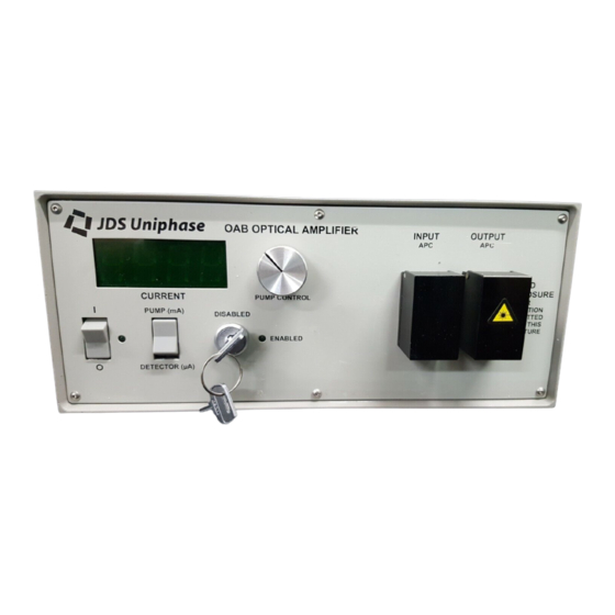
Page 23: Operating And Maintenance Instructions
Operating and Maintenance Instructions Front Panel – Booster The front panel of the unit is shown in Figure 8 and described in Table 6. Input Aperture Cassette Power Indicator Output Aperture Laser Status LED Figure 8: Front of Amplifier (Booster) Table 6: Operating Controls and LEDs Control or LED Description... -
Page 24: Operating The Amplifier
Operating the Amplifier Warning Use of protective eyewear is recommended. To ensure optimum performance, allow the amplifier to warm up for a minimum of one hour. 1. Ensure that the amplifier is inactive (LED on front panel should NOT be illuminated). 2. -
Page 25: Controls And Communication
MAP Local Interface Module. The system level commands and instructions can be found in the MAP (Multiple Application Platform) User’s Manual (JDS Uniphase part number 10108925). MAP command syntax follows general SCPI rules. The MAP command set is separated into the following subsystems: INITiate Define the measurement acquisition parameters. - Page 26 Table 7 contains the commands for the EDFA cassette. Each command header in the command tree has both a long form and a short form. The long form notation has lower and uppercase letters. The uppercase characters represent the minimum characters required for the short form command to be recognized as valid on MAP.
- Page 27 Table 7: EDFA Commands and Queries Command Parameter Format Units :FETCh :POWer :OUTPut? <C>,<S>,<D> Float dBm/W OPmin OPmax :INPut :ALS :ENABle <C>,<S>,<D> Boolean 0 (OFF) 1 (ON) <State> :ENABle? <C>,<S>,<D> Boolean 0 (OFF) 1 (ON) :LOS :LIMit <C>,<S>,<D> Float LOSmin LOSmax- <Threshold>...
-
Page 28: Standard Address Parameters
The hierarchy of commands for the MAP EDFA is shown in Figure 9 Figure 9: Hierarchy of SCPI Commands for EDFA To generate a command, follow the tree from the highest node down to the command in the bold block. Each of the commands that can be generated is explained in detail in the following subsections. -
Page 29: Fetch Commands
Fetch Commands How to Fetch the Output of the EDFA COMMAND :FETCh:POWer:OUTPut? DESCRIPTION Query the optical output power value of the specified device. INPUT FORMAT :FETch:POWer:OUTPut? <C>,<S>,<D> INPUT RANGE OUTPUT FORMAT <Power> OUTPUT RANGE Float OPmin to OPmax OPmin = - - - - - - - (TOO LITTLE LIGHT < OPmin) Opmax= +++++++ (TOO MUCH LIGHT >... - Page 30 LOCAL INTERFACE • Highlight “OA” • Press ‘Enter’ ( • Output Power will be displayed • Press ‘Exit’ ( )”...
-
Page 31: Input Commands
Input Commands How to Enable or Disable the ALS Function on the EDFA COMMAND :INPut:ALS:ENABle DESCRIPTION Enable or disable Automatic Laser Shutdown (ALS) in the event of a loss of signal (LOS) on the amplifier input. NOTE: 1. User should query the threshold of the LOS before enabling to ensure that it is high enough to accommodate the current input signal. - Page 32 LOCAL INTERFACE • Highlight “OA” • Press ‘Enter’ ( • Press 3 times to highlight “ALS Monitor” • Press to select “Enabled” or “Disabled” • Press ‘Enter’ ( • Press ‘Exit’ ( )”...
-
Page 33: How To Query The State Of Als
How to Query the State of ALS COMMAND :INPut:ALS:ENABle? DESCRIPTION Query the current state of the Automatic Laser Shutdown (ALS) monitor. INPUT FORMAT :INPut:ALS:ENABle? <C>,<S>,<D> INPUT RANGE OUTPUT FORMAT <State> OUTPUT RANGE Boolean 0 – OFF 1 - ON DEFAULT EXAMPLE The following example queries the LOS state of the module on chassis 2, slot 8, device 1. -
Page 34: How To Set The Los Threshold On The Edfa
How to Set the LOS Threshold on the EDFA COMMAND INPut:LOS:LIMit DESCRIPTION Set the Loss Of Signal (LOS) threshold of the device. If input signal power drops below the specified threshold it will have the following effects: • Bit 2 (LOS) of the device status register will be set. •... - Page 35 LOCAL INTERFACE • Highlight “OA” • Press ‘Enter’ ( • Press ‘Page->’ ( • Press 1 time to highlight “LOS Limit” • Press to select threshold for “LOS Limit” • Press ‘Enter’ ( • Press ‘Exit’ ( )”...
-
Page 36: How To Query The Los Threshold Of The Edfa
How to Query the LOS Threshold of the EDFA COMMAND :INPut:LOS:LIMit? DESCRIPTION Query the LOS limit of the device. INPUT FORMAT :INPut:LOS:LIMit? <C>,<S>,<D> INPUT RANGE OUTPUT FORMAT <threshold > OUTPUT RANGE <threshold>* Float Variable (dBm) Resolution is 0.1 dBm DEFAULT Device 1 = -23 Device 2 = -120 EXAMPLE... -
Page 37: Source Commands
Source Commands How to Set the Laser Current on the Cassette COMMAND :SOURce:CURRent:OUTPut DESCRIPTION Set the laser current in percentage of maximum laser current. INPUT FORMAT :SOURce:CURRent:OUTPut <C>,<S>,<D>,<Output> INPUT RANGE <Output>* Float 0 - 100% *resolution is 0.1% OUTPUT FORMAT None OUTPUT RANGE DEFAULT... -
Page 38: How To Query The Laser Current On The Cassette
How to Query the Laser Current on the Cassette COMMAND :SOURce:CURRent:OUTPut? DESCRIPTION Query the laser current ( % of maximum laser current ). INPUT FORMAT :SOURce:CURRent:OUTPut? <C>,<S>,<D> INPUT RANGE OUTPUT FORMAT <Output> OUTPUT RANGE <Output>* Float 0 - 100% *resolution is 0.1% DEFAULT EXAMPLE The following example query the laser current value on chassis 2, slot... -
Page 39: How To Set The Laser Status Of The Cassette
How to Set the Laser Status of the Cassette COMMAND :SOURce:STATe DESCRIPTION Set the laser to one of the following states: • Active. The laser driver is enabled. • Inactive. The laser driver is disabled. When system is powered up or reset, laser is in inactive state. NOTE: Setting the laser active does not guarantee a signal output. - Page 40 LOCAL INTERFACE • Highlight “OA” • Press ‘Enter’ ( • Press ‘Page->’ ( • Press 1 time to highlight “Laser Status” • Press to select “Enabled” or “Disabled” • Press ‘Enter’ ( • Press ‘Exit’ ( )”...
-
Page 41: How To Query The State Of The Laser On The Cassette
How to Query the State of the Laser on the Cassette COMMAND :SOURce:STATe? DESCRIPTION Query the state of the laser source. INPUT FORMAT :SOURce:STATe? <C>,<S>,<D> INPUT RANGE OUTPUT FORMAT <State> OUTPUT RANGE <State> Boolean 0 – Inactive 1 – Active DEFAULT EXAMPLE The following example queries the power mode of the laser on chassis... -
Page 42: Local Interface
Local Interface The display of the controller cassette while in manual mode is shown in Figure 10 and described in Table 8. Page 1: Chassis 1 Slot 1 Device 1/1 Optical Amplifier Input Power: 2.463 dBm Output Power: 18.617 dBm Mode: Const Current Laser Status:... - Page 43 Table 8: Monitors and Controls in Manual Mode Function Description Input Power: Provides the input signal to the amplifier from optical signal source in dBm or mW Output Power: Provides the amplified output signal from the EDFA in dBm or W Mode: “Const Current”...
-
Page 44: Device Status Information Table
Device Status Information Table The Device Status Information table is shown in Figure 11 and described in Table 9. Device Status Information Laser Active Interlock Loss Of Signal Warm Up Period Laser Power Limit Backreflection Limit Automatic Laser Shut Down Reserved Exit Figure 11: The Device Status Information Table... -
Page 45: Device Fault Monitor Table
Device Fault Monitor Table The Device Fault Monitor table is shown in Figure 12 and described in Table 10. Device Fault Monitor Laser Over Temperature TEC Over Temperature Laser Fault Reserved Reserved Reserved Reserved Exit Figure 12: The Device Fault Monitor Table Table 10: Device Fault Monitor Definitions Function Description... -
Page 46: Software Guide
Software Guide Basic Settings Screen The Basic screen is shown in Figure 13 and described in Table 11. Figure 13: Basic Functions... - Page 47 Table 11: Basic Screen Functions Function Description Reset Resets EDFA to factory settings Self Test Performs self test on cassette, the EDFA will return with a “Pass or “Fail” in the “Ready” box Refresh Refreshes all parameters on the cassette Ready Status box for “Self Test”, will reply with “Pass”...
-
Page 48: Settings Screen
Settings Screen The Settings screen is shown in Figure 14 and described in Table 12. Figure 14: Settings... - Page 49 Table 12: Settings Screen Definitions Function Description Input Power Power Displays input power in dBm or µW Loss Of Signal Limit Displays the limit at which the unit will assign loss of signal alarm. Using the user can adjust the threshold. Auto Laser Shut...
-
Page 50: Advanced Settings Screen
Advanced Settings Screen The Advanced screen is shown in Figure 15 and described in Table 13. Figure 15: Advanced Functions Table 13: Advanced Screen Definitions Function Description Spare Busy/Response Timeout The time before the cassette will send an error report if no (mS) response is received from the processor. -
Page 51: Status Settings Screen
Status Settings Screen The Status screen is shown in Figure 16 and described in Table 14. Figure 16: Status Functions Table 14: Status Screen Definitions Function Description CARD FAULTS Displays and faults detected at card level on the cassette DEVICE FAULTS Displays and faults detected at device level on the cassette Refresh Refreshes all parameters on cassette. -
Page 52: Info Screen
Info Screen The Info screen is shown in Figure 17 and described in Table 15. Figure 17: Info Screen Table 15: Info Screen Definitions Function Description Info Displays: Serial Number, Part Number, Firmware Revision, Module Revision, Hardware Revision, Assembly Date, and Description. -
Page 53: About Screen
About Screen The About screen is shown in Figure 18. Figure 18: About Screen... -
Page 54: Service
• The unit does not pass the initial inspection In the event of carrier responsibility, JDS Uniphase will allow for the repair or replacement of the unit while a claim against the carrier is being processed. Returning Shipments to JDS Uniphase JDS Uniphase only accepts returns for which an approved Return Material Authorization (RMA) has been issued by JDS Uniphase sales personnel.