
Summary of Contents for Navico Simrad RS100
- Page 1 RS100/RS100-B V100/V100-B USER MANUAL ENGLISH RS100/RS100-B V100/V100-B www.simrad-yachting.com | www.bandg.com...
-
Page 3: Warranty
Preface Disclaimer As Navico is continuously improving this product, we retain the right to make changes to the product at any time which may not be reflected in this version of the manual. Please contact your nearest distributor if you require any further assistance. -
Page 4: Optional Components
“Reset” on page 35 for more details. Regulatory compliance statements European Union Navico declare under our sole responsibility that the RS100, RS100-B, V100, and V100-B conforms with the requirements of Directive 2014/53/EU (RED). HS40 and H60 Wired Handset complies with CE under EMC Directive 2014/30/EU. -
Page 5: Rf Emissions Notice
EU RF exposure compliance notice for fixed mount VHF To be protected against all verified adverse effects, the separation distance of at least 2.1 m must be maintained between the antenna of the radio having max. 6 dBi antenna and all persons. Countries of intended use in the EU AUT - Austria BEL - Belgium... -
Page 6: Innovation, Science And Economic Development Canada (Ised)
protection against harmful interference in a residential installation. This equipment generates, uses and can radiate radio frequency energy, and, if not installed and used in accordance with the instructions, may cause harmful interference to radio communications. However, there is no guarantee that interference will not occur in a particular installation. -
Page 7: Australia And New Zealand
Navico® is a registered trademark of Navico Holding AS. B&G® is a registered trademark of Navico Holding AS. SIMRAD® is a registered trademark of Kongsberg Maritime AS, Licensed to Navico Holding AS. NMEA® and NMEA 2000® are registered trademarks of the National Marine Electronics Association. - Page 8 MMSI and ATIS ID The user MMSI (Marine Mobile Service Identity) is a unique nine digit number. It is used on marine transceivers that are capable of using DSC (Digital Selective Calling). • An MMSI remains with a vessel, even if the vessel is sold on. •...
- Page 9 Contents 11 General information 11 How to display and navigate menus 13 LCD functions 14 Keypad functions 18 Wired Handset Numeric Keys 18 Radio menus 18 Menu tree 19 Scan 20 Watch 20 Voice recorder 21 Display 22 Radio setup 25 DSC/ATIS setup 27 AIS setup 28 Alarms...
- Page 10 47 Installation 47 What’s in the box 48 Mounting guidelines 49 Mounting the Blackbox 50 Mounting the CR100 Fixed handset cradle 51 Mounting the BC-12 wireless handset cradle 52 Mounting the Speaker 54 Wiring guidelines 55 Blackbox connector details 59 Wiring diagram 60 First time startup configuration 63 VHF Radio Help and Troubleshooting Guide 63 Software updates...
- Page 11 79 Dimensional drawings 80 NRS-1 and NRS-2 Blackbox 80 HS100 and H100 Fixed Handset 81 SP100 Speaker 81 Handset Cradle (CR100) / Charger (BC-12) 82 HS40 / H60 Wireless Handset 82 Appendix 83 Country Settings table 84 NMEA 2000 compliant PGN list | 11 Contents | User Guide Style Template...
-
Page 12: General Information
General information The RS100 / V100 system provides the following features: • Up to 4 wired alphanumeric handset stations • Up to 4 wireless handsets (HS40/H60) • 4 configurable 4 W wired speaker outputs • Built-in GPS processor for connection with an external GPS antenna •... - Page 13 D Current menu item selected is highlighted. Arrow indicates additional sub-menu items for the menu option. ¼ Note: Press the X/POWER key to step backwards to the previous menu page, or exit the menus completely. Press the OK/HL key to make selections in the menu. Entry of alphanumeric data Press the keys to scroll through the alphanumeric characters, or use the keypad on the wired...
-
Page 14: Lcd Functions
Missed DSC call Low Battery (vessel) warning (activates at 10.5 V) Battery level (wireless handset) Track your Buddy feature is active TRI watch or DUAL scan is active GPS simulator is active LCD functions A Radio is Transmitting (TX) mode. Will change to BUSY when receiving B Missed call in the DSC call log C Channel is set to high power transmit D Low vessel voltage alert... -
Page 15: Keypad Functions
Keypad functions A Distress A Distress call is broadcast to all DSC equipped radios, so will create an alarm on every DSC radio within range. If position information is available it will be included in the transmission. Short press to commence a distress call. Nature of the distress can be selected from the list. Long press to initiate an immediate ‘undesignated’... - Page 16 ¼ Note: Also used for menu scrolling, editing, and backlight level adjustment. Channel DOWN Short press decreases one channel. ¼ Note: You can also directly select a channel by typing the channel number on the keypad. Long pressing the key will, after a short delay, step rapidly through the channels. ¼...
-
Page 17: Alphanumeric Keypad
• Normal radio mode: Short press to start DUAL WATCH or TRI WATCH (if ‘watch’ channel set). Refer to “Watch” on page 21 for more details. Long press to set the current channel as the watch channel. • AIS mode (NRS-2 only): Short press to increase (zoom out) the scale of the AIS plotter in one range at a time. - Page 18 Wired Handset Numeric Keys Depending on the mode the radio is in, the numeric keys on wired handsets provide additional functionality. • NORMAL mode - System is in standby: Short press enters the numeric digit (i.e. channel number). Long Press opens a pre-determined function or menu. •...
-
Page 19: Radio Menus
Radio menus Menu tree Long press the DSC/MENU key to open the main Menu page. The following shows the available menu and submenu options: ¼ Note: Main (first) level and 2nd level only. Menu Submenu Option Notes ALL SCAN ALL CHANNELS + 16 Scan MY CHANNELS MY CHANNELS + 16... - Page 20 AIS FUNCTION NRS-2 only SILENT MODE (ON/OFF) NRS-2 only AIS DISPLAY (MMSI/NAME) NRS-2 only AIS setup (>) NRS-2 only TCPA (>) NRS-2 only CONFIG VESSEL (>) NRS-2 only GPS ALERT (>) WX ALERT (>) US/CAN country modes Alarms DSC ALARM (>) CPA ALARM (>)
-
Page 21: Voice Recorder
My channels + 16 Scans all channels selected in EDIT MY CHANNELS, while also checking the priority channel after every channel step. Edit my channels ¼ Note: This function is also available as a Shortcut. Allows creation of a custom list of channels - used in a MY CHANNELS scan. Watch This menu is for choosing a watch mode to enable, as well as selection of the watch channel. -
Page 22: Time Display
Recorder • ON - Record transmitted and received VHF audio (loop recording last 60 seconds). • OFF - Disables voice recorder. Display This menu allows the user to partially customize the screen information displayed, and adjust the screen for best visibility to suit the user and operating conditions. Time display Select ON or OFF to display TIME. -
Page 23: Radio Setup
Network max level Select a maximum level. This is to ensure the backlight is never too bright if the network level is set too high. Select between 5 to 10. ¼ Note: Backlight Offset settings relate to the individual handset, not to the system. ¼... -
Page 24: Handset Speaker
Units Select SPEED to choose KNOTS, MPH, or KPH. Select COURSE to choose MAGNETIC or TRUE. A true north heading is corrected for magnetic variation. A magnetic north heading source must also output magnetic variation data if the heading is to be displayed as a true north value. - Page 25 GPS source ¼ Note: This function is also available as a Shortcut. Depending on your radio blackbox model, you can select between a Networked GPS source (NRS-1) or Internal GPS source (NRS-1 and NRS-2). ¼ Note: A valid GPS source is required for DSC and AIS functions to operate. ¼...
-
Page 26: Auto Power On
Time Time offset ¼ Note: This function is also available as a Shortcut. Select TIME OFFSET to enter the difference between UTC and local time in 15 minute increments with a maximum offset of ±13 hours. ¼ Note: Does not automatically adjust for Daylight Savings Time. Time format ¼... - Page 27 ATIS ID (EU country mode only) Enter an ATIS number to access the radio’s ATIS functionality. This unique identifier must be supplied a local radio spectrum authority. DO NOT enter a random ‘made up’ number. ¼ Note: Contact a Simrad or B&G dealer if you need to change your ATIS ID after initial input. Individual acknowledge The radio can be configured to automatically acknowledge an incoming ‘individual’...
-
Page 28: Ais Setup
DSC timeout An inactivity timeout can be set to return the radio to normal operational mode after a period of inactivity while the radio is engaged in a Distress or non-Distress DSC call: Distress Select between NONE, 5 MINS, 10 MINS and 15 MINS. (default is NO TIMEOUT). Non distress Select between NONE, 5 MINS, 10 MINS and 15 MINS. - Page 29 Additional Vessel data will be transmitted once these details are completed. Ship name Enter the ship’s name; maximum 20 alpha-numeric characters. Call sign Enter your VHF radio call sign – this must be supplied from your local radio spectrum authority. Will automatically show if it was entered during the initial startup of the radio.
- Page 30 GPS alert The GPS alert is a warning to the user that the selected GPS source is not outputting valid position data. It comprises of an audible alarm and visual alarm (screen flash and warning text). GPS alert function If set to OFF, there will be no GPS alerts including audible alarm, screen flash, and warning text. Alert volume Select between HIGH, LOW, and OFF Screen flash...
-
Page 31: Alert Volume
In this case, the T/CPA calculation deems the vessel UNSAFE and the TCPA Alert is raised. If set to OFF, there will be no T/CPA alarms regardless of the settings. It comprises of an audible alarm and visual alarm (screen flash and warning text). CPA alert function If set to OFF, the radio will not respond to T/CPA alerts including audible alarm, screen message, and screen flash. -
Page 32: Using The Wireless Handset
Wireless handset (WHS) Pair a wireless handset The pairing process only needs to be performed once per WHS: 1 Ensure the WHS that you want to pair to the radio is charged and turned OFF. ¼ Note: Ensure all other WHS’s remains OFF during this procedure. 2 Access the radio’s Main menu from a fixed handset, and select HANDSETS >... -
Page 33: Gps Status
Once the wireless handset has been paired to the radio, the screen and key functionality are mimicked on each device. Most functions that are provided on the radio can be accessed by the wireless handset with the following exceptions: • SETUP - Some setup functions are not available on the wireless handset. - Page 34 • HANDSET STATUS: Fixed Handset installed and turned ON Fixed Handset installed and turned OFF This handset Wireless Handset installed and turned ON NMEA2000 status ¼ Note: This function is also available as a Shortcut. Select to view the NMEA 2000 network diagnostics: •...
- Page 35 Reset Region and Country Use this setting to change the Region and Country settings this radio is operating in. ¼ Note: Refer to “Country Settings table” on page 94 for a listing of the Countries supported. If your Country is not listed, select INTERNATIONAL 1 First select the Region: EUROPE, USA/CAN or INTERNATIONAL 2 Then select the Country within the selected region.
-
Page 36: Dsc Call Menu
DSC call menu Digital Selective Calling (DSC) is a semi-automated method of establishing VHF, MF, and HF radio calls. One big advantage that DSC enabled radios offer is that they can receive calls from another DSC radio without being on the same channel as the calling radio. Short press the DSC / MENU key for the following options: •... - Page 37 Send a distress call using the DISTRESS key 1 Lift the red protective cover exposing the Distress key. 2 Short press the Distress key. Use the keys to select the nature of distress call from the menu. 3 Long press the Distress key. A 3-second countdown will commence before the Distress call is sent. After the Distress Call is sent, the radio waits for an acknowledgment.
- Page 38 POS REQUEST Used to request a position of another vessel. The call can be initiated by selecting: • MANUAL: enter a new vessel’s MMSI • RECENT: select a vessel in the RECENT list • CONTACTS: an existing vessel already saved in your CONTACTS list POS REPORT Used to send your vessels position to another vessel.
- Page 39 INTERVAL The frequency that ‘buddies’ are polled with position requests can be selected between: 5, 15, 30 and 60 minutes. Contacts Used for the administration and calling of CONTACTS and GROUPS. VIEW/ADD CONTACT Use this to create, edit, or delete up to 50 vessel CONTACTS with names and MMSI’s. Contacts are stored by name, in alphabetical order.
- Page 40 AIS menu (NRS-2 only) ⚠ Warning: Valid GPS data must be entered into this radio before the AIS functions can be used. The plotter PPI function will not display targets accurately with incorrect GPS data. ⚠ Warning: Take note that not all vessels will have an AIS transceiver installed or turned on, so will NOT be taken into consideration for Collision Avoidance.
-
Page 41: T/Cpa Approach Screen
2 AIS target details will be displayed on the left of the screen. Either the vessels name or MMSI will be displayed (if the information is available) depending on the setting you selected in Section “6-2 AIS data display format (AIS DISPLAY)”. Also the target’s bearing and distance to you are displayed. ¼... -
Page 42: Using The Fog Horn
Fog Horn, Intercom, and Hailer ¼ Note: An appropriate Hailer speaker must be connected to the Hailer wiring before the HAILER or FOG HORN functions can be used. Using the FOG Horn The FOG horn will sound certain international standard fog horn tones through the Hailer speaker depending on the mode selected. -
Page 43: Using The Hailer
Using the HAILER The Hailer function allows you to make a high volume announcement using the handset through the Hailer speaker to people or vessels. The Hailer function also features a LISTEN mode - this mode uses the Hailer speaker as a microphone to listen for a response on the main radio. - Page 44 My channels The MY CHANNELS page is accessed by long pressing the numeric 9 key. This page provides a shortcut to frequently accessed channels. The first time this page is opened, the entire channel list is shown so that the desired shortcut channels can be selected.
- Page 45 Shortcuts The Shortcuts page is accessed by long pressing the VOL/SQL selector key. This page is provided as a shortcut to frequently accessed functions. The shortcut options available on this page are subject to selections made in ADD/EDIT SHORTCUTS. Add/Edit Shortcuts Long press the VOL/SQ selector key.
-
Page 46: Man Overboard (Mob)
MOB and NAV functions Man Over Board (MOB) An MOB is generated by press and hold SCAN and TRI keys together. The screen will change to MOB navigation mode to help navigate back to the MOB location: • DST shows the current distance to MOB waypoint. •... - Page 47 Navigation Function (NAV) Long press 6 to enter the NAV (Navigation) mode. The screen will change to navigation mode displaying the vessel’s current SOG and COG Press the X / POWER key to exit NAV mode and return to normal radio operation mode. | 47 MOB and NAV functions | RS100 / RS100-B / V100 / V100-B User Manual...
-
Page 48: Installation
Installation What’s in the box The following items should be supplied in the box. Check before starting the installation and contact your dealer if an item is missing. ¼ Note: A VHF antenna is not provided. Consult your Simrad or B&G dealer for advice on selecting the correct antenna for your installation. -
Page 49: Mounting Guidelines
S/S Pan-head machine screw (M3 x 20) S/S flat washer (M3) S/S split washer (M3) S/S hex nut (M3) Warranty card Wired Speaker with the following items: Description # of items SP100 Speaker Speaker mounting box AP-6 Accessory pack: Speaker kit Speaker mounting gasket Speaker bezels AP-7 Accessory pack: Speaker mounting kit... - Page 50 Mounting the Blackbox ¼ Notes: Allow easy access to the Blackbox for connection to the 12 V DC power supply, the antenna(s), and additional wiring. • The Blackbox can be positioned vertically on a bulkhead or horizontally. Avoid positions that might get wet or hot, such as in the engine compartment or close to the bilge.
- Page 51 Mounting the CR100 Fixed handset cradle ¼ Notes: • The CR100 Fixed handset cradle is a passive unit and does not require a power supply. • The Fixed handset is provided with a 5m (16.4’) handset extension cable. Ensure the chosen location is within the length of the installed cable to the Blackbox.
- Page 52 Mounting the BC-12 wireless handset cradle ¼ Notes: • The BC-12 Wireless Handset Cradle requires a +12V DC supply for charging. Ensure the selected location allows for the power wire at the rear of the unit. • The handset LCD screen has an optimum horizontal and vertical viewing angles within approx. +/-20 deg.
-
Page 53: Mounting The Speaker
Mounting the Speaker ¼ Note: The wired speaker is provided with a 2m (6.5’) fixed cable. The cable maybe extended if necessary using a minimum 14 AWG 2-pair cable. Flush mounting 1 Cut a 98 mm (3.86”) diameter hole in the mounting surface, allowing space for the speaker’s overall dimensions. -
Page 54: Surface Mounting
Surface mounting 1 Remove the plastic bezels that cover the screw holes on speaker front. Mark the screw holes using the speaker as the template. 2 Drill holes of appropriate size for the fasteners to be used. • Drill a hole in the mounting surface for the speaker wire, ensuring hole is near one of the corner screw holes, to prevent cable pinching under speaker. -
Page 55: Wiring Guidelines
Mounting the GPS-500 antenna ¼ Note: The GPS-500 antenna is only optional for NRS-1 but mandatory for NRS-2. • It is not recommended that the GPS antenna is mounted up a mast where the motion of the vessel will cause the antenna to swing and potentially reduce the accuracy of the GPS position. •... - Page 56 Do’s: • Make drip and service loops. • Use cable-tie on all cables to keep them secure. • Solder/crimp and insulate all wiring connections if extending or shortening the cables. Extending cables should be done with suitable crimp connectors or solder and heat shrink. Keep joins as high as possible to minimize possibility of water immersion.
- Page 57 Cable Grommets There are two cable sealing rubber grommets at the front of the Blackbox. Wires must pass through the allocated slot in the grommet (L1-7 and R1-7) as indicated to create an IPx5 seal. Slots have a thin rubber membrane to ensure unused slots remain sealed. Press the wire through the allocated slot to break the seal prior to adding the connector.
- Page 58 FUSE MIC+ MIC+ RX_A 10 A MIC- MIC- RX_B TX_A TX_B TR-B TR-B HRN- HAILER TR-A TR-A HRN+ 12V DC SSW- SSW+ SKP1-4 GND (A) Optional ground connection. May help with induced noise issues. Ring terminal size M3, #5. FUSE (B) 10 A mini-blade type fuse.
-
Page 59: Plug-In Connections
AUX (G) Auxiliary connections for NMEA 0183, Horn key and AIS Silent Switch: RX_A NMEA 0183 TX_A of chart plotter, or GPS data RX_B NMEA 0183 TX_B of chart plotter, or GPS data TX_A NMEA 0183 RX_A of chart plotter TX_B NMEA 0183 RX_B of chart plotter HRN-... -
Page 60: Wiring Diagram
A AIS Antenna (NRS-2 only) B GPS-500 (NRS-1 optional; NRS-2 mandatory) C NMEA 2000 GPS Source (Optional on NRS-1 only) D Navico MFD VHF Antenna Wireless Dipole Antenna (Optional 6 meter extension cable available) G Fixed Handsets (HS1 mandatory, HS2, HS3, HS4 optional) - Page 61 First time startup configuration ⚠Warning: Never operate the radio without the antenna connected. This may damage the transmitter. The first time the radio is powered up, the user is prompted to make a series of setting selections in order to allow the radio to perform to its full potential. Some steps must be completed; some are optional and can be completed later.
- Page 62 6 Set the time offset for your region. Time Offset in 24 hour format: 7 Select 12 HOUR or 24 HOUR format: 8 Select CONFIGURE AIS to configure CLASS-B AIS (NRS-2 only). 62 | Installation | RS100 / RS100-B / V100 / V100-B User Manual...
-
Page 63: Software Updates
VHF Radio Help and Troubleshooting Guide This guide aims to help resolve an issue you may encounter with the system during installation or operation. In some cases, a restart of the system may remedy the situation; however, other steps may need to be followed such as performing a factory reset. Additionally, refer to the built-in system diagnostics screens to assist in resolving issues. -
Page 64: Troubleshooting
Error message Error type Reason Details AIS VSWR Pop-up message AIS antenna VSWR detection Detect at each AIS ERROR! (open circuit or short circuit) transmission. Either the antenna is missing (open circuit), or damaged (short circuit). Can also be due to corrosion of wiring or connections. - Page 65 Incorrect wiring Confirm wiring is correct Check volume is not at minimum and adjust as Volume is set too low No sound from required wired speaker Check speaker assignments including offset Incorrect speaker value. You may need to set a minimum offset assignment value so speaker volume does not go too low Incorrect GPS Source...
- Page 66 AIS Class-B (NRS-2 only) Issue Reason Details A VHF antenna must be connected to the AIS No AIS Antenna antenna port All details in the AIS setup screen must be AIS details not completed completed before the AIS system can commence transmitting.
-
Page 67: System Features
RS100/B, V100/B Specifications System features Local/Distant control: LL Position polling: Group call: Call logs: Yes - 20 individual and 10 distress Channel naming: Handset naming: Dual watch / Tri watch: Favorite channel scan: All scan: User programmable MMSI: User programmable ATIS ID: MMSI and NAME directory: Yes - 50 vessel contacts and 20 group contacts Software updates:... -
Page 68: Vhf Transceiver
NRS-1, NRS-2: IPx5 Waterproof: HS100, H100, SP100: IPx7 HS40, H60: IPx7 NRS-1, NRS-2: 2.5 kg (5.5 lbs) Weight: HS100, H100: 1.46 kg (3.2 lbs) SP100: 0.45 kg (1.0 lbs) VHF Transceiver VHF Mode: 16K0G3E (FM) / 16K0G2B (DSC) Usable channels (country specific): International, Europe, USA, Canada, Weather Channel spacing: 25 KHz... -
Page 69: Wireless Specifications
Built-in GPS Receiver Receiving frequency: 1575.42 MHz Tracking code: C/A code Number of channels: 72 channels Horizontal accuracy: <10 m Position fixing time: Warm start: 30s, Cold start: 90s Position update interval: 1 second typical Wireless specifications Wireless standard: 802.11 b/g/n20 Operating frequency: 2412~2472 MHz (for EU);... -
Page 70: Channel Charts
Channel charts The following channel charts are provided for reference only and may not be correct for all regions. It is the operators’ responsibility to ensure correct channels and frequencies are used for local regulations. EU and International channel chart With reference to Appendix 18 (Rev.WRC-15) (See article 52). - Page 71 156.875 156.900 161.500 156.925 161.525 1078 156.925 156.925 2078 161.525 156.950 161.550 1019 156.950 156.950 2019 161.550 156.975 161.575 1079 156.975 156.975 2079 161.575 157.000 161.600 1020 157.000 157.000 2020 161.600 y), wa) 157.025 161.625 y), wa) 157.050 161.650 y), wa) 157.075 161.675 y), wa)
- Page 72 86 w), ww), 157.325 161.925 1086 w), ww), 157.325 2086 w), ww), 161.925 z), zx) 157.350 161.950 1027 z), zz) 157.350 157.350 ASM 1 161.950 161.950 (was 2027) z), zz) 157.375 157.375 z), zx) 157.400 162.000 1028 z), zz) 157.400 157.400 ASM2 162.000...
- Page 73 j) Channel 70 is to be used exclusively for digital selective calling for distress, safety and calling. k) Channel 13 is designated for use on a worldwide basis as a navigation safety communication channel, primarily for intership navigation safety communications. It may also be used for the ship movement and port operations service subject to the national regulations of the administrations concerned.
- Page 74 mobile service using digitally modulated emissions and subject to coordination with affected administrations. (WRC-15) wa) In Regions 1 and 3: • Until 1 January 2017, the frequency bands 157.025-157.175 MHz and 161.625-161.775 MHz (corresponding to channels: 80, 21, 81, 22, 82, 23 and 83) may be used for digitally modulated emissions, subject to coordination with affected administrations.
-
Page 75: Usa Channel Chart
USA channel chart Transmitting frequencies (MHz) Channel S/D/R Channel name Restrictions designator From ship stations From coast stations 156.300 156.300 SAFETY 156.400 156.400 COMMERCIAL 156.450 156.450 CALLING 156.500 156.500 COMMERCIAL 156.550 156.550 156.600 156.600 PORT OPS/VTS 156.650 156.650 BRIDGE COM 156.700 156.700 PORT OPS/VTS... - Page 76 1080 (was 80A) 157.025 157.025 COMMERCIAL 1081 (was 81A) 157.075 157.075 RESTRICTED 1082 (was 82A) 157.125 157.125 RESTRICTED 1083 (was 83A) 157.175 157.175 RESTRICTED USA weather channels Transmitting frequencies (MHz) Channel S/D/R Channel name Restrictions designator From ship stations From coast stations 162.550 NOAA WX1 RX ONLY...
- Page 77 Non-Weather-Related Events NWR-SAME Code Status State and Local Codes-Optional Avalanche Watch Operational Avalanche Warning Operational Child Abduction Emergency Operational Civil Danger Warning Operational Civil Emergency Message Operational Earthquake Warning Operational Evacuation Immediate Operational Fire Warning Operational Hazardous Materials Warning Operational Law Enforcement Warning Operational Local Area Emergency...
-
Page 78: Canada Channel Chart
Canada channel chart Frequencies Channel S/D/R Channel Name: Restrictions designator MHz (ship) MHz (coast) 156.050 160.650 TELEPHONE 156.100 160.700 TELEPHONE 156.150 160.750 TELEPHONE 156.200 160.800 CANADIAN CG 156.250 160.850 TELEPHONE 156.300 156.300 SAFETY 156.350 160.950 TELEPHONE 156.400 156.400 COMMERCIAL 156.450 156.450 156.500 156.500... - Page 79 156.975 161.575 TELEPHONE 157.025 161.625 TELEPHONE 157.075 161.675 TELEPHONE 157.125 161.725 CANADIAN CG 157.175 161.775 CANADIAN CG 157.225 161.825 TELEPHONE 157.275 161.875 TELEPHONE 157.325 161.925 TELEPHONE 157.375 157.375 PORT OPS 157.425 157.425 PORT OPS 1001 156.050 156.050 COMMERCIAL 1005 156.250 156.250 PORT OPS/VTS 1007...
-
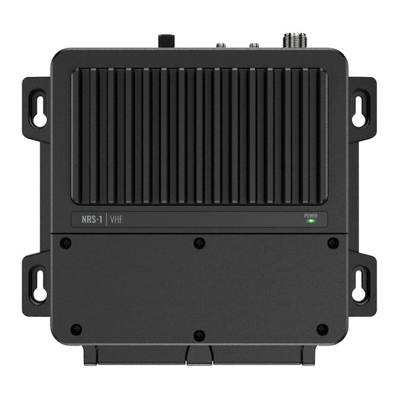
Page 80: Dimensional Drawings
Dimensional drawings NRS-1 and NRS-2 Blackbox 212.0 mm (8.35”) 190.0 mm (7.48”) HS100 and H100 Fixed Handset 29.50 mm 68.0 mm (2.68”) (1.16”) | 79 Dimensional drawings | RS100 / RS100-B / V100 / V100-B User Manual... - Page 81 SP100 Speaker 109.5 mm (4.31”) 35.0 mm (1.38”) 98.0 mm (3.86”) 27.0 mm (1.06”) Handset Cradle (CR100) / Charger (BC-12) 55.7 mm (2.19”) 32.9 mm (1.29”) 65.7 mm 54.6 mm (2.59”) (2.15”) 80 | Dimensional drawings | RS100 / RS100-B / V100 / V100-B User Manual...
- Page 82 HS40 / H60 Wireless Handset 67.9 mm 32.0 mm (2.68”) (1.26”) 49.2 mm (1.94”) 31.0 mm (1.22”) | 81 Dimensional drawings | RS100 / RS100-B / V100 / V100-B User Manual...
- Page 83 Appendix Country Settings table Region Country INTERNATIONAL INTERNATIONAL AUSTRALIA NEW ZEALAND USA/CAN UNITED STATES CANADA EUROPE AUSTRIA BELGIUM BULGARIA CROATIA CYPRUS CZECH REPUBLIC DENMARK ESTONIA FINLAND FRANCE GERMANY GREECE HUNGARY IRELAND ICELAND ITALY LIECHTENSTEIN LITHUANIA LUXEMBOURG LATVIA MOLDOVIA MALTA NETHERLANDS NORWAY POLAND PORTUGAL...
-
Page 84: Nmea 2000 Compliant Pgn List
NMEA 2000 compliant PGN list Description ● ● 59392 ISO Acknowledgement ● ● 59904 ISO Request ● 60160 Transport Protocol, Data Transfer ● ● 60416 Transport Protocol ● ● 60928 ISO Address Claim ● 65240 Commanded Address ● ● 126208 NMEA —... - Page 85 Description ● 129810 AIS Class B CS Static Data Report, Part B ● 130074 Route and WP Service - WP List -WP Name & Position ● 130306 Wind Data 130840 Source Selection □ □ 130842 AIS and VHF Message Transport ●...
- Page 87 | www.bandg.com ®Reg. U.S. Pat. & Tm. Off, and ™ common law marks. Visit www.navico.comintellectual-property to review the global trademark rights and accreditations for Navico Holding AS and other entities.