
Related Manuals for Emerson Daniel 700 Series


Summary of Contents for Emerson Daniel 700 Series
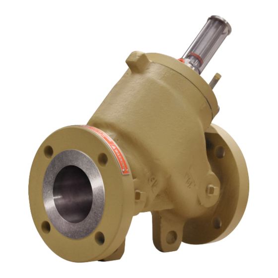
- Page 1 User manual P/N 3-9008-553, Rev AO November 2020 ™ Daniel Model 700 Control Valve NPS 2 through 16 / Class 150-600...
- Page 2 Emerson employees. Emerson will not accept your returned equipment if you fail to follow Emerson procedures. Return procedures and forms are available on our web support site at www.emerson.com, or by phoning the Emerson Customer Service department.
-
Page 3: Table Of Contents
User manual Contents P/N 3-9008-553 November 2020 Contents Part I Plan Chapter 1 Introduction......................7 1.1 Purpose of this manual........................ 7 1.2 Hazard messages......................... 7 1.3 Personnel qualifications....................... 7 1.4 Warranty restrictions........................9 1.5 Assistance............................9 1.6 Description of the Model 700 Control Valves................9 1.7 Agency certifications for control valves Model 700.............. - Page 4 Contents User manual November 2020 P/N 3-9008-553 Part IV Maintain Chapter 9 Planned maintenance....................49 9.1 Maintenance considerations...................... 49 9.2 Tools required for mechanical components................49 9.3 Disassemble/Assemble the control valve................... 49 9.4 Mechanical assembly......................... 53 9.5 Planned maintenance tasks....................... 62 Chapter 10 Corrective maintenance...................
-
Page 5: Part I Plan
User manual Plan P/N 3-9008-553 November 2020 Part I Plan User manual... - Page 6 Plan User manual November 2020 P/N 3-9008-553 Daniel Series 700 Control Valve...
-
Page 7: Chapter 1 Introduction
Personnel qualifications Read and follow all instructions, dangers, warnings, and cautions to avoid personal injury or property damage during system operation. Emerson is not responsible for damage or injury resulting from unsafe use of products, lack of maintenance, incorrect installation of equipment or system operation. - Page 8 To ensure safe and proper performance, only informed and trained personnel should install, operate, repair and maintain this product. For further questions about training requirements, contact your local Emerson representative. Operations risk assessment must be used and followed in conjunction with this document when performing all online retrieval operations.
-
Page 9: Warranty Restrictions
Emerson assumes no responsibility for incidents, or consequences of incidents, occurring as a result of the use of this product by others than Emerson or its designated personnel, and have no liability whatsoever for any such work. - Page 10 Introduction User manual November 2020 P/N 3-9008-553 The Daniel Model 700 Control Valves have the following characteristics: • Modular construction: All internal parts including seat ring can be removed with the cylinder assembly without disturbing line connections. • No diaphragms or stuffing boxes •...
- Page 11 User manual Introduction P/N 3-9008-553 November 2020 Figure 1-1: Pilot in closed position A. Needle valve / strainer B. Manual pilot control C. Inlet pressure D. Outlet pressure Fully open - No control Figure 1-2 the valve is fully open. Y-port (P3) is open to Z-port (P2). The pressure on the bottom of the piston (P1) is greater than the pressure at (P3) plus spring force.
- Page 12 Introduction User manual November 2020 P/N 3-9008-553 Figure 1-2: Pilot in fully open position A. Needle valve / strainer B. Manual pilot control C. Inlet pressure D. Outlet pressure Open controlled position Figure 1-3 the valve is partially open. Y-port (P3) is open to Z-port (P2) but is being restricted by the control pilot.
- Page 13 User manual Introduction P/N 3-9008-553 November 2020 Figure 1-3: Pilot in partially open position A. Needle valve / strainer B. Manual pilot control C. Inlet pressure D. Outlet pressure E. Controlled pressure User manual...
- Page 14 Introduction User manual November 2020 P/N 3-9008-553 1.6.4 Parts list for the Series 700 Control Valves Figure 1-4: Part identification for an NPS 2-12 inch Control Valve NOTICE Item numbers are not meant to be consecutively numbered. Table 1-1: Part description for Model 700 Control Valve NPS 2 - 12 Item number Description Quantity...
- Page 15 User manual Introduction P/N 3-9008-553 November 2020 Table 1-1: Part description for Model 700 Control Valve NPS 2 - 12 (continued) Item number Description Quantity Retaining ring Spring O-ring Cylinder head Screw Jack-out screws Indicator stem visual Indicator stem micro-switch Magnet Retaining ring Indicator adapter...
- Page 16 Introduction User manual November 2020 P/N 3-9008-553 Table 1-1: Part description for Model 700 Control Valve NPS 2 - 12 (continued) Item number Description Quantity Cap plug Set Screw Cylinder assembly class 150 and Cylinder assembly class 600 Daniel Series 700 Control Valve...
- Page 17 User manual Introduction P/N 3-9008-553 November 2020 Figure 1-5: Part identification for an NPS 16 inch Control Valve Table 1-2: Part description for Model 700 Control Valve NPS 16 Item number Description Quantity Cylinder O-ring Seat ring Piston O-ring User manual...
-
Page 18: Agency Certifications For Control Valves Model 700
Introduction User manual November 2020 P/N 3-9008-553 Table 1-2: Part description for Model 700 Control Valve NPS 16 (continued) Item number Description Quantity Backup ring O-ring Spring O-ring Cylinder head O-ring Screw Jack-out screws Indicator stem micro-switch Nuts Valve body Studs Pipe plug Cap plug... -
Page 19: Operating Conditions And Specifications
User manual Operating conditions and specifications P/N 3-9008-553 November 2020 Operating conditions and specifications Operating conditions for the control valve Table 2-1: Operating conditions for the control valve Condition type Description Fluid phase Liquid Process temperature -20° F to 150° F (-29° C to 66° C) Optional process -50°... - Page 20 Operating conditions and specifications User manual November 2020 P/N 3-9008-553 Table 2-1: Operating conditions for the control valve (continued) Condition type Description Maximum safe working Flange connections/Ratings (DIN) for valve sizes DN50 and DN400: pressure • DIN PN16 MWP at 120° C: 16 bar •...
- Page 21 User manual Operating conditions and specifications P/N 3-9008-553 November 2020 Table 2-1: Operating conditions for the control valve (continued) Condition type Description Valve capacity is a capacity coefficient that defines as the number of US gpm of water that flows through a valve with a pressure drop of 1 psi across the valve.
- Page 22 Operating conditions and specifications User manual November 2020 P/N 3-9008-553 2.1.2 Environmental conditions WARNING EQUIPMENT HAZARD Never use this equipment for any purpose other than its intended use. Failure to comply may result in death, serious personal injury and/or property damage. Table 2-2: Environmental conditions Parameter type Description...
-
Page 23: Specifications For The Control Valve
User manual Operating conditions and specifications P/N 3-9008-553 November 2020 Specifications for the control valve 2.2.1 Interface requirements WARNING EXCEEDING REQUIREMENTS HAZARD Control valve requirements are defined to ensure safe equipment operation. Do not exceed published specifications. Failure to comply may result in death, serious injury and/or damage to the equipment. Table 2-3: Interface requirements Requirements Description... - Page 24 Operating conditions and specifications User manual November 2020 P/N 3-9008-553 NOTICE Flush lines to remove welding bead, pipe scale, etc. NOTICE Install the valve in a horizontal line with the cylinder head at the top. Figure 2-1: Valve orientation WARNING EQUIPMENT HAZARD Never use this equipment for any purpose other than its intended use.
- Page 25 User manual Operating conditions and specifications P/N 3-9008-553 November 2020 2.2.3 Minimum clearances for installation, operation and maintenance For certified prints, consult the factory. Figure 2-2: Dimensions of the control valve Table 2-4: Weight and volume table for the control valve (Approximate) Size 150 lb.
- Page 26 Operating conditions and specifications User manual November 2020 P/N 3-9008-553 Table 2-5: Dimensions for the control valve Class 150 Class 300 Class 600 Class 150-300 Class 600 Valve inches mm inches mm inches mm inches mm inches mm Size 10-1/4 260 10-1/2 267 11-1/2 292 9-5/8...
-
Page 27: Control Valve Handling
User manual Control valve handling P/N 3-9008-553 November 2020 Control valve handling Receive the control valve WARNING EQUIPMENT HANDLING AND OPERATING HAZARD Wear personal protective equipment appropriate to the situation when working with the control valve. Adhere to all safety standards and best practices for operating the equipment. - Page 28 Control valve handling User manual November 2020 P/N 3-9008-553 3.2.3 Storage conditions Store the control valve in a safe area to avoid damage. WARNING CRUSHING HAZARD During installation or removal of a control valve, always place the unit on a stable platform or surface that supports its assembled weight.
-
Page 29: Prepare The Control Valve For Use
User manual Prepare the control valve for use P/N 3-9008-553 November 2020 Prepare the control valve for use Lifting conditions WARNING CRUSHING HAZARD During installation or removal of a control valve, always place the unit on a stable platform or surface that supports its assembled weight. Failure to comply may allow the control valve to roll, resulting in death, serious injury or equipment damage. -
Page 30: Lifting Requirements For Personnel
Prepare the control valve for use User manual November 2020 P/N 3-9008-553 Lifting requirements for personnel 4.2.1 Safety precautions using appropriately rated lifting slings WARNING LIFTING HAZARD The lifting instructions are for installation and removal of a Daniel control valve only and do not address lifting the control valve while it is attached or bolted to piping. - Page 31 User manual Prepare the control valve for use P/N 3-9008-553 November 2020 Figure 4-1: Correct sling attachment • Only use slings with ratings that exceed the weight to be lifted. Reference all safety standards for safety factors that must be included when calculating the load rating. CAUTION SLING HAZARD Never allow the slings to come in contact with the visual indicator, position indicator,...
-
Page 32: Configure The Control Valve
Prepare the control valve for use User manual November 2020 P/N 3-9008-553 Configure the control valve The factory configures Daniel control valve internal components. Inspect the internal components before installation. 4.3.1 Orientation and position of the control valve Flow direction NOTICE Comply with local government regulations and company requirements. - Page 33 User manual Prepare the control valve for use P/N 3-9008-553 November 2020 WARNING EQUIPMENT HAZARD Never use this equipment for any purpose other than its intended use. Failure to comply may result in death, serious personal injury and/or property damage. 4.3.2 Piping recommendations The design of the control valve has not been assessed for the effects of traffic, wind or...
- Page 34 Prepare the control valve for use User manual November 2020 P/N 3-9008-553 Daniel Series 700 Control Valve...
-
Page 35: Part Ii Install
User manual Install P/N 3-9008-553 November 2020 Part II Install User manual... - Page 36 Install User manual November 2020 P/N 3-9008-553 Daniel Series 700 Control Valve...
-
Page 37: Chapter 5 Installation Prerequisites
User manual Installation prerequisites P/N 3-9008-553 November 2020 Installation prerequisites Pre-start checks Ensure that the pipeline is completely free of all foreign material before installing the valve. User manual... - Page 38 Installation prerequisites User manual November 2020 P/N 3-9008-553 Daniel Series 700 Control Valve...
-
Page 39: Chapter 6 Installation Procedure
User manual Installation procedure P/N 3-9008-553 November 2020 Installation procedure External components assembly The control valve is assembled at the factory. The components do not need to be uninstalled or reinstalled unless maintenance is required. CAUTION SURFACE TEMPERATURE HAZARD The control valve body and piping may be extremely hot or cold. Wear personal protective equipment appropriate to the situation when working with the control valve. - Page 40 Installation procedure User manual November 2020 P/N 3-9008-553 Daniel Series 700 Control Valve...
-
Page 41: Testing The Product
User manual Testing the product P/N 3-9008-553 November 2020 Testing the product Commission the control valve After installation, commission the control valve to ensure that the equipment is working properly. Procedure 1. Inspect all bolts used to secure the control valve in-line to ensure that proper mounting procedures have been followed and that flange connections are leak- free. - Page 42 Testing the product User manual November 2020 P/N 3-9008-553 Daniel Series 700 Control Valve...
-
Page 43: Part Iii Operate
User manual Operate P/N 3-9008-553 November 2020 Part III Operate User manual... - Page 44 Operate User manual November 2020 P/N 3-9008-553 Daniel Series 700 Control Valve...
-
Page 45: Chapter 8 Operation Parameters
User manual Operation parameters P/N 3-9008-553 November 2020 Operation parameters Control valve normal operation Models 700 Control Valve is versatile valve in the market. It can incorporate any single or multiple control function(s) to meet the exact requirements for on - off in modulating control of liquid products. - Page 46 Operation parameters User manual November 2020 P/N 3-9008-553 CAUTION EQUIPMENT DAMAGE Read the entire recommended procedure for all installation operations and maintenance procedures before attempting to install or disassemble the valve. Disassembly of this cylinder assembly is different from previous Daniel control valves and requires strict adherence to the procedures outlined in this manual.
-
Page 47: Part Iv Maintain
User manual Maintain P/N 3-9008-553 November 2020 Part IV Maintain User manual... - Page 48 Maintain User manual November 2020 P/N 3-9008-553 Daniel Series 700 Control Valve...
-
Page 49: Chapter 9 Planned Maintenance
User manual Planned maintenance P/N 3-9008-553 November 2020 Planned maintenance Maintenance considerations Read and understand all instructions and operating procedures before performing maintenance procedure, internal component inspection, or field requirement changes. To ensure safe and accurate performance, only informed and trained personnel should install, operate, repair and maintain this product. - Page 50 Planned maintenance User manual November 2020 P/N 3-9008-553 The control valve must be cleaned completely inside the housing components and stored/ shipped as it was received. Refer to Storage Preparations for cleaning instructions. After the meter is shut down, refer to Cylinder disassembly (NPS 2-12) for the detailed disassembly procedure.
- Page 51 User manual Planned maintenance P/N 3-9008-553 November 2020 Figure 9-1: Using the piston to remove the seat ring from the 150/300 lb cylinder 1. Cylinder 3. Seat ring 4. Piston 9. Turn the cylinder over with the ports on top when removing the high pressure seat ring.
- Page 52 Planned maintenance User manual November 2020 P/N 3-9008-553 • Drip pan • (3) hoist rings 1-in to 8-in nnc 10,000 lb, part number 1-504-90-094 Procedure 1. Completely block all product flow to the valve and drain the process line. 2. Disconnect "Y" port on top of cylinder head and relieve pressure in the valve. Warning SPRING FORCE HAZARD Use extreme caution when removing the cylinder head from the valve body.
-
Page 53: Mechanical Assembly
• Fastener lubrication and coatings It is impossible for Emerson personnel to know all the variable conditions (some listed above) that your valve (under your care) will see in actual service. Only the owner or user, after careful consideration of a valve's service conditions, can specify a torque value to achieve an adequate seal. - Page 54 1153 (1563) 1281 (1737) Values are FOR REFERENCE only. Emerson provides the torque values in this table to help users establish a starting point to achieve an adequate unit assembly clamping force. Torque values reflect threads and nut bearing surfaces being bare metal well-lubricated with thread compound assembled in a controlled factory environment.
- Page 55 User manual Planned maintenance P/N 3-9008-553 November 2020 Cylinder head/valve body torque sequencing patterns • 2-in 150-300 — Ø 3/8-in Studs • 2-in 600 — Ø 7/8-in Studs • 3-in 150-300 — Ø 7/16-in Studs • 3-in 600 — Ø 7/8-in Studs •...
- Page 56 Planned maintenance User manual November 2020 P/N 3-9008-553 A. 8-in 150-300 Ø ¾-in Studs • • 8-in 600 — Ø 7/8-in Studs • 10-in 150-300 — Ø 7/8-in Studs • 12-in 150-300 — Ø 1-1/8-in Studs Daniel Series 700 Control Valve...
- Page 57 User manual Planned maintenance P/N 3-9008-553 November 2020 • 10-in 600 — Ø 1-in Studs • 12-in 600 — Ø 1-1/8-in Studs User manual...
- Page 58 Planned maintenance User manual November 2020 P/N 3-9008-553 • 12-in 900 — Ø 1-1/4-in Studs • 16-in 150-300 — Ø 1-in Studs • 16-in 600 — Ø 1-3/8-in Studs 9.4.2 Standard cylinder reassembly Reassembly of a control valve without a position indicator Procedure 1.
- Page 59 User manual Planned maintenance P/N 3-9008-553 November 2020 6. With the piston in a vertical position, nose end down, place the O-ring into the groove on the piston. (If the valve is a high-pressure model, the piston will require PTFE backup rings on either side of the O-ring.) 7.
- Page 60 Planned maintenance User manual November 2020 P/N 3-9008-553 Reassembly of a control valve with a microswitch-type position indicator Procedure 1. Place the valve in a vertical position with the head up. Place the indicator stem into the center hole in the cylinder head, and press it into the retaining ring in the piston. You may have to wiggle the indicator stem a little to get it into position.
- Page 61 User manual Planned maintenance P/N 3-9008-553 November 2020 4. For ease of installation, secure cylinder assembly to cylinder heads using hand pressure or arbor press. WARNING DISASSEMBLY HAZARD When performing any disassembly procedure caution is required as the cylinder head is bolted to a spring loaded cylinder assembly. Service should only be performed by trained and qualified service personnel.
-
Page 62: Planned Maintenance Tasks
Planned maintenance User manual November 2020 P/N 3-9008-553 Planned maintenance tasks Table 9-2: Planned maintenance tasks Task Recommended action Inspect Implement a periodic inspection program to ensure all parts are free from damage during its use due to process, ambient or other abnormal conditions. -
Page 63: Chapter 10 Corrective Maintenance
10.1 Control valve troubleshooting Use the table below to troubleshoot the control valve. Contact the nearest Emerson Flow services center for assistance with repairs of Daniel products. It is important that servicing be performed by trained and qualified service personnel. -
Page 64: Verify The Return To Operational Condition
Corrective maintenance User manual November 2020 P/N 3-9008-553 10.2 Verify the return to operational condition Once corrective maintenance has taken place, verify that the control valve is working properly by following the steps below. Procedure 1. Inspect all bolts used to secure the control valve in-line to ensure that proper mounting procedures have been followed and that flange connections are leak- free. -
Page 65: Chapter 11 Spare Parts
User manual Spare parts P/N 3-9008-553 November 2020 Spare parts 11.1 Order spare parts Contact Emerson Flow services for Daniel products and provide the following information when ordering parts: • Daniel control valve serial number • Part description • Quantity... - Page 66 Spare parts User manual November 2020 P/N 3-9008-553 Daniel Series 700 Control Valve...
-
Page 67: Chapter 12 Decommission
5. Do not use metal clamping devices in direct contact with control valve parts or surfaces. Refer to Mechanical disassembly after shutting down the control valve. 12.2 Shipment of the control valve Refer to Emerson Flow services for Daniel products information in the preface of this document. User manual... - Page 68 Daniel ("Daniel") is an Emerson Automation Solutions brand. The Daniel name and logo are trademarks of Emerson. The Emerson logo is a trademark and service mark of Emerson Electric Co. All other trademarks are the property of their respective companies.