Advertisement
Quick Links
Air-Conditioners For Building Application
PLFY-P·VEM-E
INSTALLATION MANUAL
For safe and correct use, read this manual and the outdoor unit installation manual thoroughly before installing
the air-conditioner unit.
For use with the R410A
Bei Verwendung von R410A
A utiliser avec le R410A
Para utilizar con el R410A
Uso del refrigerante R410A
Para utilizaçao com o R410A
Til anvendelse sammen med R410A
R410A ile beraber kullanmak için
For bruk med R410A
English (GB)
Advertisement

Related Manuals for Mitsubishi Electric City Multi PLFY-P VEM-E Series


Summary of Contents for Mitsubishi Electric City Multi PLFY-P VEM-E Series
- Page 1 Air-Conditioners For Building Application For use with the R410A Para utilizaçao com o R410A PLFY-P·VEM-E Bei Verwendung von R410A Til anvendelse sammen med R410A A utiliser avec le R410A R410A ile beraber kullanmak için Para utilizar con el R410A Uso del refrigerante R410A For bruk med R410A INSTALLATION MANUAL English (GB)
- Page 2 Contents 1. Safety precautions ..................2 4. Electrical work ...................7 2. Installing the indoor unit ................2 5. Test run ....................12 3. Refrigerant pipe and drain pipe ..............5 6. Installing the grille ..................14 Note: : Indicates an action that must be avoided. tions”.
- Page 3 2. Installing the indoor unit 950 D 860 – 910 C locations (Fig. 2-2) 20 – 45 20 – 45 795 B Caution: accessory with the grille), make an opening in the ceiling so that the main unit can be installed as shown in the diagram. (The method for using the template and the gauge is shown.) * Before using, check the dimensions of template and gauge, because they * The dimensions of ceiling opening can be regulated within the range shown in...
- Page 4 2. Installing the indoor unit A Main unit B Grille constructors and interior decorators should be consulted for details. C Pillar (1) Extent of ceiling removal: The ceiling must be kept completely horizontal and the ceiling foundation (framework: wooden slats and slat holders) must be reinforced in order to protect the ceiling from vibration.
- Page 5 excluding those of the optional multi function casement. A Drain pipe B Ceiling C Grille D Refrigerant pipe (liquid) E Refrigerant pipe (gas) (mm) F Main unit Models When the optional multi-functional casement is installed, add 135 mm to the dimen- 20, 25, 32, 40, 50 76.5 63, 80, 100, 125...
- Page 6 A Refrigerant pipe and heat insulation 1 Wrap the enclosed large-sized pipe cover around the gas pipe, making sure that B Pipe cover (large) the end of the pipe cover touches the side of the unit. C Pipe cover (small) 2 Wrap the enclosed small-sized pipe cover around the liquid pipe, making sure D Refrigerant pipe (gas) that the end of the pipe cover touches the side of the unit.
- Page 7 1. Loosen the two screws securing the electrical wiring service panel, and then turn the electrical wiring service panel. [Fig. 4-1 1] 2. Loosen the one screw securing the electrical wiring service panel at the cable entry (remote controller cable and indoor-outdoor connection cable), and then turn the service panel to the position shown in the diagram.
- Page 8 <When wiring two indoor-outdoor connection cables> ited. terminal is prohibited. cut outs on both sides. prohibited. Cut outs side into separate spaces with one cable positioned above the other. When using a single cable, a round crimped terminal or other terminal work is prohibited.
- Page 9 Types of transmission cable Shielding wire CVVS or CPEVS Types of remote control cable 2-core cable (unshielded) Cable diameter More than 1.25 mm² Cable diameter 0.3 to 1.25 mm² Length Less than 200 m Length Less than 200 m Types of remote control cable Shielding wire MVVS Cable diameter 0.5 to 1.25 mm²...
- Page 10 Note: (slide switch). Select a suitable setting from the table below according to the instal- lation location. PLFY-P20-P80VEM PLFY-P100-P125VEM Silent Standard High ceiling Silent Standard High ceiling SW21-1 SW21-2 SW21-1 SW21-2 SW21-1 SW21-2 SW21-1 SW21-2 SW21-1 SW21-2 SW21-1 SW21-2 SW21-3 4 direction 2.5 m 2.7 m...
- Page 11 The following settings can be made in the initial setting mode. Item Setting Fig. 4-8 Temperature unit Time display AUTO mode Pair No. 0–3 Backlight button 1 to stop the air conditioner. 1. Press the button 2. 2. Press the The Function setting screen will be displayed and the function No.
- Page 12 5. Test run Warning: 5.2. Test run The following 3 methods are available. Press to save the setting. Press to return to the previous screen. Press to bring up the Main menu. 5 Backlit LCD Operation settings will appear. When the backlight is off, pressing any button turns the backlight on and it will stay lit for a certain period of time depending on the screen.
- Page 13 5. Test run 1 Select “Service” from the Main menu, and press the button. 2 When the Service menu is selected, a window will appear asking for the password. (Fig. 5-2) To enter the current maintenance password (4 numerical digits), move the cursor to the digit you want to change with the button, and set each number (0 through 9) with the button.
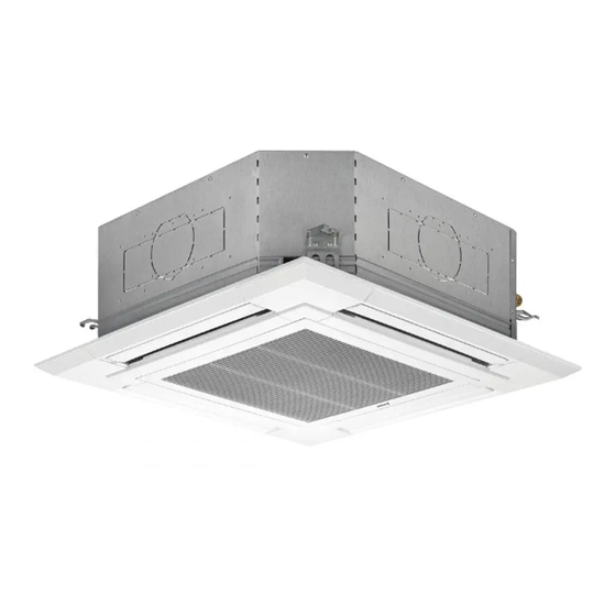
- Page 14 Accessory name Q’ty Remarks 1 Grille 950 × 950 (mm) 2 Installation gauge (Divided into 4 parts) 3 Screw (4 × 16) For PLP-6EAE, PLP-6EALE, PLP-6EALME 4 i-see Sensor corner panel For PLP-6EAE, PLP-6EALE, PLP-6EALME 5 Wireless remote controller For PLP-6EALM, PLP-6EALME Included when equipped with the wire- 6 Remote controller holder When equipped with the wireless remote controller...
- Page 15 A Main unit B Corner of drain pipe C Claw on the main unit and put them together temporarily by hanging the hook of the grille to the claw of the main unit. D Grille 1 E Hole on the grille F Hook for temporary installation G Screw with captive washer Note:...
- Page 16 Note: * If the corner panels are not attached surely, they may fall off while the main unit is operating. reverse order to install the intake grille and the corner panel. customer. A Screw (4 × 16) B Corner panel C Safety strap D Hook E Refrigerant pipe...
- Page 17 This product is designed and intended for use in the residential, commercial and light-industrial environment. this manual before handing it to the customer. RG79F135K01 Printed in UNITED KINGDOM...