Table of Contents
Advertisement
Quick Links
Advertisement
Table of Contents

Summary of Contents for JDS Uniphase TB9 Series
- Page 1 sales@artisantg.com artisantg.com (217) 352-9330 | Click HERE Find the VIAVI Solutions / JDSU TB9226-Z-FP at our website:...
- Page 2 TB9 SERIES OPTICAL GRATING FILTER User’s Manual Artisan Technology Group - Quality Instrumentation ... Guaranteed | (888) 88-SOURCE | www.artisantg.com...
- Page 3 Artisan Technology Group - Quality Instrumentation ... Guaranteed | (888) 88-SOURCE | www.artisantg.com...
-
Page 4: Table Of Contents
Operating Environment ....................10 Temperature ......................10 Humidity......................10 Ventilation......................10 Storing and Shipping.....................10 Claims and Repackaging...................10 Returning Shipments to JDS Uniphase .............10 Cleaning Connectors.....................11 Cleaning the UCA Bulkheads..................13 Powering and Warming up the Grating Filter ..............14 Operating and Maintenance Instructions ................16 Front Panel........................16 Connector Panel....................17... - Page 5 Serial Polling the Status Register ..............27 Generating a Service Request Interrupt ............27 RS232 Interface Programming Example ...............28 For sales and service information, contact JDS Uniphase or your local representative. JDS Uniphase Corporation 570 West Hunt Club Road Nepean, Ontario, Canada...
-
Page 6: Safety Information, Instructions, And Symbols
Safety Information, Instructions, and Symbols Safety Information Classification The unit consists of an exposed metal chassis that is connected directly to earth via a power cord and, therefore, is classified as a Class 1 instrument. Class 1 refers to equipment relying on ground protection as a means of shock protection. -
Page 7: Safety Instructions
Failure to comply with any of these instructions or with any precaution or warning contained in the user’s manual is in direct violation of the standards of design, manufacture, and intended use of the unit. JDS Uniphase assumes no liability for the customer’s failure to comply with any of these safety requirements. - Page 8 • Use only the type of fuse specified by the manufacturer as appropriate for this unit. Do not use repaired fuses, and avoid any situations that can short- circuit the fuse. • Unless absolutely necessary, do not attempt to adjust or perform any maintenance or repair procedure when the unit is opened and connected to a power source.
-
Page 9: Safety Symbols
Safety Symbols The following symbols and messages can be marked on the unit (Table 1). Observe all safety instructions that are associated with a symbol. Table 1: Safety Symbols Symbol Description Laser safety. See the user’s manual for instructions on handling and operating the unit safely. -
Page 10: Compliance
Compliance CE Compliance The unit has been designed and tested to comply with directive 73/23/EEC and its subsequent amendments by the European Community (EC or CE). The directive relates to electrical equipment designed for use within certain voltage limits. It ensures that electrical equipment is constructed with good engineering practice in safety matters. -
Page 11: General Information And Specifications
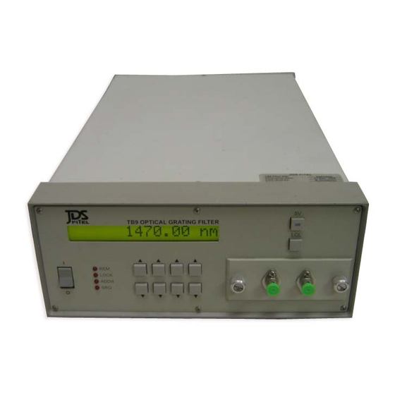
General Information and Specifications General Information This user’s manual for the TB9 Series Optical Grating Filter contains complete operating instructions. The TB9 grating filter is designed for high performance laboratory and production testing of single-mode fiber-based components and subsystems (Figure 1). Single- and double-pass grating configurations are available to provide high rejection and narrow bandwidth. -
Page 12: Key Features
Key Features • Grating-based optical filter • Full width at half maximum (FWHM) as low as 0.22 nm • High rejection • Single-mode fiber in and out • GPIB parallel interface and RS232 serial interface Applications • Spontaneous emission suppression •... - Page 13 Repeatability 0.05 nm Accuracy 0.2 nm Table 3: Other specifications Electrical Input voltage 100 to 240 V AC, 50 to 60 Hz Power consumption 80 VA maximum Physical Weight 4 kg Dimensions (W x H x D) 21.2 x 8.9 x 35.5 cm 19 in (48.26 cm) rack- 2U high, ½...
-
Page 14: Getting Started
Getting Started The TB9 Series Optical Grating Filter consists of the filter unit, an AC power cord, a user's manual, the test report and a warranty card. Before Initializing and Operating the Unit Inspect the unit for any signs of damage. -
Page 15: Operating Environment
• The unit does not pass the initial inspection In the event of carrier responsibility, JDS Uniphase will allow for the repair or replacement of the unit while a claim against the carrier is being processed. Returning Shipments to JDS Uniphase JDS Uniphase only accepts returns for which an approved Return Material Authorization (RMA) has been issued by JDS Uniphase sales personnel. -
Page 16: Cleaning Connectors
and full serial number of the unit, the RMA number, and an itemized statement of claimed defects must be included with the return material. Ship return material in the original shipping container and packing material. If these are not available, packaging guidelines are as follows: 1. - Page 17 • No. 0 Phillips screwdriver Cleaning the jumper connector: Figure 2: Typical jumper connector 1. Apply alcohol to a small area of a lint-free towel and rub the end of the ferrule over the wet area. 2. Wipe the ferrule on a dry area of the lint-free towel. 3.
-
Page 18: Cleaning The Uca Bulkheads
Figure 3: Typical Mating Sleeve Cleaning the UCA Bulkheads Cleaning Procedure: The TB9’s are manufactured with protective covers to shield users from the potentially harmful signal that could be emitted from the optical ports. The covers are designed to provide sufficient clearance for maintenance, cleaning, and for changing or replacing adapters. -
Page 19: Powering And Warming Up The Grating Filter
Figure 4: Universal Connector Adapter 4. Clean the internal cavity with a pipe cleaner and alcohol (a rotating motion will yield the best results). The adapter is a critical component that can provide highly reliable mating of optical connector, if properly maintained. 5. - Page 20 (1460 or 1525 depending on the model). If a malfunction is detected during power-up, an error message is displayed. 3. Allow the instrument to stabilize for two hours before use. An electrical current is supplied continuously to the heater elements of the TB9 grating filter until its internal temperature reaches the set point.
-
Page 21: Operating And Maintenance Instructions
Operating and Maintenance Instructions Front Panel The front of the filter is shown in Figure 5 and described in Table 4 and Table 5. TB9 grating filters with a built-in splitter or switch have three fiberoptic connectors. TB9 OPTICAL GRATING FILTER LOCK ADDR Figure 5: Front of Filter... -
Page 22: Connector Panel
Description Indicates that the unit interrupt logic has generated a service request interrupt (SRQ) on the GPIB interface. Connector Panel Two fiberoptic connectors, or cable feed-throughs, are mounted on a removable panel. On TB9P there are two universal connector laser safety covers in the same place as the connectors on the standard TB9. -
Page 23: Setting The Gpib Address
Calibrating the Grating Filter Calibration for the unit is factory-set. To ensure reliable performance, yearly recalibration is recommended. Return the unit to JDS Uniphase for recalibration. Maintaining the Grating Filter Clean the connector ends before every mating to increase the operating life of the connectors, minimize insertion loss, and reduce backreflection. -
Page 24: Programming Guide
Programming Guide The following programming instructions for the TB9 grating filter are intended for users who are familiar with remote interfaces and how to send or receive messages over a device. A detailed description of the GPIB interface is in ANSI/IEEE Std. 488.1-1987 IEEE Standard Digital Interface for Programmable Instrumentation published by the Institute of Electrical and Electronics Engineers. -
Page 25: Rs232 Interface
Mnemonic IEEE 488.1 Function remote/local, complete capability parallel poll, no capability device clear, complete capability device trigger, no capability controller, no capability electrical interface, open collector drivers RS232 Interface RS232 Pin Assignment and Functions The RS232 pin assignment is shown in Figure 8 and the interface functions are listed in Table Figure 8: RS232 Pin Assignment Table 7: RS232 Functions Name... -
Page 26: Connecting The Pc Serial Port To The Tb9 Grating Filter
Figure 9: RS232 Driver Pin Assignment Caution • Do not exceed 100 mA. Connecting the PC Serial Port to the TB9 Grating Filter To connect a 25-pin PC serial port to the grating filter, use 25-pin D-sub plug connectors at both ends of the connection. -
Page 27: Operation And Query Commands
Operation and Query Commands Operation and query commands control instrument functions and are interface-independent. Command Parser Rules • A command consists of a mnemonic (for example, CLOSE) and, if required, a data parameter. The mnemonic and the data parameter must be separated by at least one space. -
Page 28: Query Commands
Wavelength Control Sets the wavelength of the TB9 filter; the default unit is in meters (M): • M = meters • MM = millimeters • UM = micrometers • NM = nanometers SRE i SQR Mask Writes a decimal number to the SRQ mask register (see the Status Reporting and Service Request Control section). -
Page 29: Status Reporting And Service Request Control
Identifier Returns a string that identifies the manufacturer, the TB9 filter series, the serial number (or 0 if unavailable), and the firmware level, for example, JDS Uniphase, TB9, 0, 0. Status Reporting and Service Request Control The TB9 grating filter maintains two eight-bit registers that are used for status reporting and enabling the GPIB service request interrupt: •... -
Page 30: Status Register
• SRQ mask register Status Register The status register records errors and other events that have occurred in the filter (Table 10). When an event occurs, the filter status logic sets the corresponding bit to 1. The status register can be read at any time because the bits stay set until the register is read at least once. Table 10: Status Register Status Register Bit 7... -
Page 31: Gpib Programming Examples
The SRQ mask register can unmask more than one event at a time. The first unmasked event to change from 0 to 1 causes an interrupt. To acknowledge this interrupt, the GPIB interface can be serial polled or the status register can be read with STB?. The first time the filter is serial polled after an SRQ is generated, bit 6 is on. -
Page 32: Serial Polling The Status Register
OPEN "GPIB0" FOR INPUT AS #2 PRINT #1, "ABORT" PRINT #1, "OUTPUT 05;WVL?" PRINT #1, "ENTER 05" INPUT #2, x PRINT x Serial Polling the Status Register This sample changes the wavelength setting and reads the status register continuously until the output has settled. -
Page 33: Rs232 Interface Programming Example
INPUT #2, sr ' read status register PRINT sr ' verify SRQ bit is set PRINT #1, "SPOLL 05" ' serial poll again to verify SRQ bit is cleared INPUT #2, sr ' read status register PRINT sr RETURN RS232 Interface Programming Example This section provides a programming example for controlling the TB9 grating filter over the RS232 interface.