Advertisement
R.F. Digital Single Channel 7 Day
Programmable Room Thermostat
Transmitter & Receiver Kit
Part No. 720030501
Part No. 720030601
Part No. 720030701
© Baxi Heating UK Ltd 2009
I N S TA L L AT I O N & O P E R AT I N G
AUTO
PROG
I N S T R U C T I O N S
Please keep these instructions
in a safe place.
If you move house, please hand
them over to the next
occupier.
Advertisement

Related Manuals for Baxi 720030501


Summary of Contents for Baxi 720030501
- Page 1 Transmitter & Receiver Kit Part No. 720030501 Part No. 720030601 Part No. 720030701 AUTO PROG Please keep these instructions in a safe place. If you move house, please hand them over to the next occupier. © Baxi Heating UK Ltd 2009...
-
Page 2: Table Of Contents
CONTENTS Section Page 1.0 Introduction 2.0 Locating the Transmitter 4 3.0 Fitting the Receiver 4.0 Transmitter Layout 5.0 Setting the Transmitter 6.0 Batteries & Specification 11 7.0 Communication Checks 12 © Baxi Heating UK Ltd 2009... -
Page 3: Introduction
4.The Receiver can be fitted anywhere in the property relative to the appliance as it is wired directly to the appliance switched live, providing good radio frequency communication will be maintained. Receiver Unit Fig. 2 © Baxi Heating UK Ltd 2009... -
Page 4: Locating The Transmitter
(see above). 4. Once the optimum position has been established drill & plug the wall (if wall mounting). Secure the Transmitter with the screws supplied and refit the batteries. Replace the cover. © Baxi Heating UK Ltd 2009... -
Page 5: Fitting The Receiver
Receiver cover. Fig. 6 CAUTION: 230V ! Do not remove the Receiver cover unless the electrical supply is isolated ! Max. Fuse 1A max. (not supplied) Relay 1 3A Switched Fused Spur Fig. 7 © Baxi Heating UK Ltd 2009... -
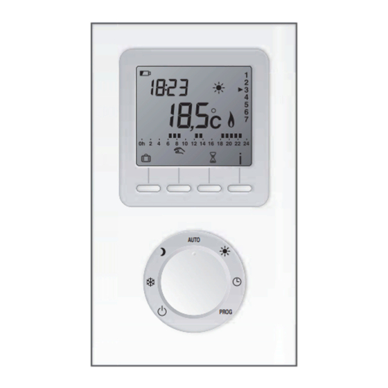
Page 6: Transmitter Layout
Current Mode (only displayed (e.g. Hi) when battery low) Current Day (e.g.Wednesday) Current Time ‘Burner On’ Indicator Temperature Programme Profile (Measured) Multi-Function Automatic Mode Buttons AUTO Frost Protection Time Setting PROG Shutdown Programming Selector Knob © Baxi Heating UK Ltd 2009... -
Page 7: Setting The Transmitter
14°C).This is the temperature that will be maintained during the periods of PROG the day when the Central Heating is programmed to be ‘ON’ (see below). Fig. 11 4.Turn the knob to exit the setting mode. © Baxi Heating UK Ltd 2009... - Page 8 Turn the Selector Knob to:- Switches current mode, Manual temperature mode (from 30 minutes to 72 hours) e.g. Hi to Lo, for continuous Lo or vice versa for continuous Hi Fig. 13 for continuous Frost Protection © Baxi Heating UK Ltd 2009...
- Page 9 5.0 Setting the Transmitter Holiday Mode (Figs. 14 & 15) In this mode a temperature from 5°C to 15°C can be set to be maintained for a period from 1 to 365 days. 1.Turn the Selector Knob to the AUTO position.
- Page 10 2.This will continue until communication is of time it is recommended that the re-established (see Section 7.2). Transmitter batteries are replaced. Baxi Group is not liable for any 3.When in this mode the heating can be additional fuel costs incurred whilst in Emergency Mode.
-
Page 11: Batteries & Specification
Receiver Specification • 240V ac 50 Hz (+/- 10 %) power supply • Class II insulation • 868 MHz transmission frequency • IP 44 - IK 04 Protection • Operation temperature -5°C to +50°C © Baxi Heating UK Ltd 2009... -
Page 12: Communication Checks
• Press left hand button for more than Technical Enquiries 0844 871 1555 10 seconds Website www.baxi.co.uk e&oe • ‘init’ will be displayed • Press ‘OK’ to confirm or ‘C’ to cancel © Baxi Heating UK Ltd 2009 Comp N 720124602 - (1/10)