Table of Contents
Advertisement
"Providing Access to the World"
International Corporate Hdqrs: P.O. Box 310
1-800-THE LIFT
®
(574) 946-6153
35634 Rev. C
December 2010
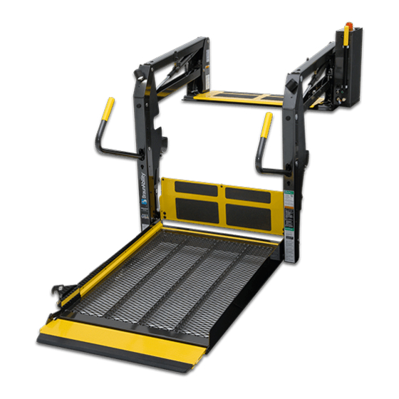
Service Manual for:
NL
Millennium
Series
Public Use Wheelchair Lifts
Series
DOT — Public Use Lift
DOT — Public Use Lift
"DOT — Public Use Lift" verifies that this platform lift meets the
"public use lift" requirements of FMVSS No. 403. This lift may be
installed on all vehicles appropriate for the size and weight of the
lift, but must be installed on buses, school buses, and multi-
purpose passenger vehicles other than motor homes with a gross
vehicle weight rating (GVWR) that exceeds 4,536 kg (10,000 lb).
®
®
Winamac, IN 46996 USA
FAX: (574) 946-4670
2
2
CA
CA
W ARNING
Read manual
before installing
or servicing lift.
Failure to do so
may result in
serious bodily
injury and/or
property damage.
Advertisement
Table of Contents

Related Manuals for Braun NL Millennium 2 Series


Summary of Contents for Braun NL Millennium 2 Series
- Page 1 Service Manual for: Millennium Series Public Use Wheelchair Lifts Series DOT — Public Use Lift DOT — Public Use Lift “DOT — Public Use Lift” verifies that this platform lift meets the “public use lift” requirements of FMVSS No. 403. This lift may be installed on all vehicles appropriate for the size and weight of the lift, but must be installed on buses, school buses, and multi- purpose passenger vehicles other than motor homes with a gross...
- Page 2 Braun certified technician, and the lift is operated by an instructed person. Sincerely, THE BRAUN CORPORATION Ralph W.
-
Page 3: Table Of Contents
Bottom Parallel Arm Assembly ......... 27 Hydraulic Cylinder Assembly - Main......28 Vertical Arm Assembly..........29 Handrail Assembly ........... 30 NL917IB-2 & NL917FIB-2 Platform Assembly ..... 31 NL919IB-2 & NL919FIB-2 Platform Assembly ..... 32 Warranty Braun ® Limited Warranty .......... 33-35 Page 1... -
Page 4: Lift Terminology
Lift Terminology Visual Threshold Warning Pump Module (Front) Main Cylinders (2) Audible Threshold Warning Hand-Held Pendant Control (not visible) Top Parallel Arms (2) Adjustable Quiet-Ride Stow Blocks (2) Towers (2) Unfold Assist Compression Springs (2) Platform Lights (2) Vertical Arm Covers (4) Threshold Warning Handrails (2) -
Page 5: Switch And Sensor Locations
Switch and Sensor Locations *Up & Unfold Microswitch Assy. 975-3121A *Unfold Microswitch *Up Microswitch Threshold Strip Switch 33337A Right Inboard *Threshold / Alarm Left Outboard & Partial Fold Microswitch Assy. 975-3121A *Threshold / Alarm Microswitch *Partial Fold Microswitch Stow Interlock Microswitch IB Occupied &... -
Page 6: Certification Checklist Diagnostic Procedures
403/404 compliant. If an operation does not function as described or a condition is not met, follow the refer- enced procedures to correct the problem or contact a Braun Corporation Product Support representative. • Vehicle movement is prevented unless the lift door is closed, ensuring the lift is stowed. -
Page 7: Platform Fold Pressure Adjustment
Platform Fold Pressure Adjustment 1. See Tower 4 (Fold) Switch Adjustment in the Tower Microswitch Adjustment section for proper microswitch setting before adjusting the platform fold pressure. 2. Position the platform at the floor level loading position. 3. Loosen the hex nut on the adjustment screw Note: Secure adjustment (do not remove hex nut). -
Page 8: Platform Angle Adjustment
Platform Angle Adjustment Lowering Sequence Requirements Figure A 1. The outboard end (toe) of the platform must contact the ground first to ensure the spring-loaded outer barrier unfolds fully. See Figure A. Barrier 2. The inboard end (heel) of the platform must lower fully Heel (vertical arms must contact ground when fully lowered). -
Page 9: Platform Stop Blocks
Platform Angle Adjustment Adjustment Allen screws are To raise the outboard end of Note: Both adjustment screws provided on each side of the lift platform - turn adjustment must be adjusted equally. screw clockwise. platform for adjusting the platform angle. Adjust platform angle as Apply Loctite ®... -
Page 10: Tower Microswitch Adjustment
Tower Microswitch Adjustment TOWER TOWER TOWER TOWER 32943 32942 Figure E TOWER TOWER TOWER TOWER 32943 32942 Note: Left (rear) pump lift Note: Review adjustment depicted. Right (front) pump procedures below and adjust lift is a mirrored image. as needed only. Tower 1 (Unfold) Switch Adjustment Tower 3 (Alarm) Switch Adjustment Floor Position from Stow... -
Page 11: Lubrication Diagram
Maintenance and Lubrication Lubrication Diagram Hydraulic Cylinder Parallel Arm Pivot Bushings (8) Pivot Pin Bearings (16) Saddle Bearing (2) ™ Lift-Tite Latches (Tower Pivot Points - 2) Parallel Arm Pivot Pin Bearings (16) Handrail Pivot Pin Bearings (4) Inner Fold Arm Roller Pin Bearings (4) Inner Roll Stop... -
Page 12: Maintenance And Lubrication Schedule
The maintenance and lubrication procedures specified 4500 cycle maintenance in this schedule must be performed by a Braun autho- procedures. These authorized service rized service representative at the scheduled intervals intervals are a general technician. - Page 13 Maintenance and Lubrication Schedule See Certification Checklist Diagnostic Procedures Verify FMVSS 403 / 404 Certification Checklist Correct as needed. Inspect lift for wear, damage or any abnormal condition Correct as needed. Inspect lift for rattles Cycles Check roll stop cylinder for leaks Place platform at floor level and remove drain plug from roll stop cylinder overflow chamber.
- Page 14 Perform all procedures listed in previous section also Inspect cotter pins on platform pivot pin (2) Resecure, replace or correct as needed Hydraulic Fluid (Pump) - Check level. Note: Fluid Use Braun 32840-QT (Exxon ® Univis HVI 26). should be changed if there is visible contamination.
- Page 15 Maintenance and Lubrication Schedule Inspect vertical arm plastic covers Resecure or replace if needed. Inspect power cable Resecure, repair or replace if needed. Mounting Check to see that the lift is securely anchored to 4500 the vehicle and there are no loose bolts, broken Cycles welds, or stress fractures.
- Page 16 NOTES This page intentionally left blank. Page 14...
-
Page 17: Lift Electrical Schematic
Lift Electrical Schematic RD(18) DESCRIPTION SYMBOL PLATFORM LIGHTS (OPTION) BK(18) BK(18) RD(18) GN(20) CAPACITOR BK(18) BK(18) RD(18) IB RAISED SWITCH MICROSWITCH LIFT LIGHT BK(18) RD(18) GN(20) SWITCH BOX BK(18) BK(18) RD(18) RELAY BK(22) BK(20) DIODE RD(22) RD(20) BK(18) RD(18) OR(20) BRIDGING RD(18) MICROSWITCH... -
Page 18: Lift Wiring Diagram
Lift Wiring Diagram RD(18) Platform Lights (Option) Light Relay Counter RD(18) 4-COND WIRE CODE 4-COND WIRE CODE COLOR COLOR GN(18) 1 2 3 BLACK(18) BLACK(18) BLUE(18) RED(18) 7 8 9 WHITE(18) WHITE(18) NOT USED NOT USED 9-COND WIRE CODE 9-COND WIRE CODE COLOR COLOR GN(18) -
Page 19: Hydraulic Schematic
Hydraulic Schematic .50 GPM Orifice Main Relief Orifice Valve Platform Outer Barrier PUMP Fold Relief Fold Relief Solenoid Valve Solenoid Valve 2500 Down Roll Stop Down Valve Solenoid Valve Outer Barrier Fold Relief BACKUP Relief Valve Valve PUMP Outer Barrier Opposite Pump Side Cylinder... -
Page 20: Hydraulics Parts List
* Raw material items ordered and priced per inch (order specified length). (complete) (complete) Coil Coil #31122 #31122 Hydraulic Fluid When adding or changing hydraulic fluid, use Braun 32840-QT (Exxon ® Univis HVI 26) hydraulic fluid (do not mix with Dextron III or Cartridge Cartridge other hydraulic fluids). -
Page 21: Hydraulics Diagram
Hydraulics Diagram Hydraulic Repair For repair of a hydraulic hose or cylinder, read this. Service Bulletin 27049 Hydraulic Pump Page 19... -
Page 22: Pump Module
Pump Module Parts List NL917IB-2 NL917FIB-2 Item Qty. Description NL919IB-2 NL919FIB-2 Pump Module (complete), 12 Volt, Rear 947-4516RNA 947-4516FNA Pump Assembly (M268-0117) 12V-120G - Triple Relief (Includes Items 1 & 2) 34330-12V 34330-12V Solenoid, Up - 4-Post Trombetta - Angle 35310 35310 Housing, Pump (Complete Assembly 947-2513RNA or 947-2513FNA Includes Items 3 - 20) -
Page 23: Pump Module Diagram
Pump Module Diagram Pump Mounting Bolts Apply Loctite ® Threadlocker Red 271™ or equivalent to the three pump mount- ing bolts (items 25 and 26) if a blue nylon patch is not present on the bolts when retrofitting an M268 pump as- sembly. -
Page 24: Nl917Ib-2 Base Plate Assembly
Exploded Views and Parts Lists NL917IB-2 Base Plate Assembly DWG. NOTES 1) LOOP TAPESWITCH WIRE BACK AND SECURE WITH WIRE TIE 2X. 2) TRIM AND TUCK WIRE TIE CLASP INTO HOLE 4X. 3) APPLY LOCTITE ® THREADLOCKER RED 271™ OR EQUIVALENT TO ALL #25527 SCREWS. "A"... -
Page 25: Nl917Fib-2 Base Plate Assembly
Exploded Views and Parts Lists NL917FIB-2 Base Plate Assembly DWG. NOTES 1) LOOP TAPESWITCH WIRE BACK AND SECURE WITH WIRE TIE 2X. 2) TRIM AND TUCK WIRE TIE CLASP INTO HOLE 4X. ® 3) APPLY LOCTITE THREADLOCKER RED 271™ OR EQUIVALENT TO ALL #25527 SCREWS. NOTE: 3 "A"... -
Page 26: Nl919Ib-2 Base Plate Assembly
Exploded Views and Parts Lists NL919IB-2 Base Plate Assembly DWG. NOTES 1) LOOP TAPESWITCH WIRE BACK AND SECURE WITH WIRE TIE 2X. 2) TRIM AND TUCK WIRE TIE CLASP INTO HOLE 4X. 3) APPLY LOCTITE ® THREADLOCKER RED 271™ OR EQUIVALENT TO ALL #25527 SCREWS. "A"... -
Page 27: Nl919Fib-2 Base Plate Assembly
Exploded Views and Parts Lists NL919FIB-2 Base Plate Assembly DWG. NOTES 1) LOOP TAPESWITCH WIRE BACK AND SECURE WITH WIRE TIE 2X. 2) TRIM AND TUCK WIRE TIE CLASP INTO HOLE 4X. ® 3) APPLY LOCTITE THREADLOCKER RED 271™ OR EQUIVALENT TO ALL #25527 SCREWS. NOTE: 3 "A"... -
Page 28: Top Parallel Arm Assembly
Exploded Views and Parts Lists Top Parallel Arm Assembly - Front ITEM QTY. PART NO. DESCRIPTION 10058 NUT-5/16-18 HEX/AUTO-BK 10068 WASHER-5/16" LOCK/AUTO-BK 15858BK BOLT-CARR 5/16-18 X 3/4/AUTO-BK 16368 WASHER-5/16" EXTERNAL TOOTH 24440 BOLT-5/16-18 X 3/4-BHSC/AUTO-BK 28593A ASSY-BLOCK-GUIDE-PLATFORM-STOW 955-2392CLXT BKT.-QUIET-RIDE MTG.-955 14993 RIV-POP-SD66BS-3/16"-.25/.38/AUTO-BK 915-0703... -
Page 29: Bottom Parallel Arm Assembly
Exploded Views and Parts Lists Bottom Parallel Arm Assembly - Pump Side ITEM QTY. DESCRIPTION PART NO. 18349 NUT-#10-32 W/LOCKWASHER/AUTO-BK 32514NA ASSY-IB OCCUPIED 34398 WASHER-0.906"ID X 1.25"OD X .075"TH/ZINC 24011 BEARING-FLANGE-3/4" X 3/8"-12FDU06 945-3458NKS ARM-PARALLEL/BOTTOM-SWITCH (Incl. Items 1-3) Bottom Parallel Arm Assembly - Opposite Pump Side ITEM QTY. -
Page 30: Hydraulic Cylinder Assembly - Main
Exploded Views and Parts Lists Hydraulic Cylinder Assembly - Main RETRACTED 29.146 STROKE 14.625 EXTENDED 43.771 30° ±10° ITEM QTY. PART NO. DESCRIPTION 15150 ELBOW-1/4 NPT 90° 1/4 BARB 26667 ELBOW-7/16-20 M/O-RNG/37*/.035 ORFICE C1514.3-0408N CYLINDER-14.625"/29.146 RETRACTED Page 28... -
Page 31: Vertical Arm Assembly
Exploded Views and Parts Lists Vertical Arm Assembly - Rear DWG. NOTES 1) INSERT SOCKET OF LIGHT ASSY THRU TOP KEY NOTE: 1 WHILE INSTALLING LIGHT. TIGHTEN SCREWS. 2) HARNESS TO BE TUCKED INSIDE CHANNEL. 3) APPLY LOCTITE ® THREADLOCKER BLUE 242 ®... -
Page 32: Handrail Assembly
Exploded Views and Parts Lists Front Handrail Assembly ITEM QTY. PART NO. DESCRIPTION 25171 BOLT - 3/8-16 X 3/4" FLBHSCS-GD8 10069 WASHER - 3/8" LOCK 11513 RIV-POP-SD64BS-3/16"-.13/.25/AUTO-BK 29185 BALL STUD-13MM W/ 3/8-16 FEMALE THREAD 29186 GAS SPRING-14.468 EXT/8.956 COM-P1=1150N 30227 SPACER-UHMW 0.75 OD X 0.39 ID X 0.25 13617 NUT-3/8-16 UNC HEX LOCK/AUTO-BK... -
Page 33: Nl917Ib-2 & Nl917Fib-2 Platform Assembly
Exploded Views and Parts Lists NL917IB-2 & NL917FIB-2 Platform Assembly DWG NOTES 1) APPLY BOUNDARY DECAL (ITEM 28) 48 1/8" FROM FRONT EDGE OF PLATFORM TO LEADING EDGE OF DECAL. 2) APPLY BOUNDARY DECALS (ITEM 27) 1/2" ABOVE PLATFORM SURFACE EXCLUDING GRATING AND 1/2"... -
Page 34: Nl919Ib-2 & Nl919Fib-2 Platform Assembly
Exploded Views and Parts Lists NL919IB-2 & NL919FIB-2 Platform Assembly DWG NOTES 1) APPLY BOUNDARY DECAL (ITEM 28) 48 1/8" FROM FRONT EDGE OF PLATFORM TO LEADING EDGE OF DECAL. 2) APPLY BOUNDARY DECALS (ITEM 27) 1/2" ABOVE PLATFORM SURFACE EXCLUDING GRATING AND 1/2"... -
Page 35: Braun Limited Warranty
10,000 cycles and the cost of labor to repair or replace those parts for one (1) year or 3,000 cycles. If The Braun Corporation receives the warranty registration card within 20 days after the lift is put into service, the warranty labor coverage will increase from one (1) year or 3,000 cycles to three (3) years or 10,000 cycles. - Page 36 (30) days for repairs to be com- pleted, you must, to the extent permitted by law, notify Braun directly, in writing, at the above address, of the unsuccessful repair(s) of the alleged defect(s) so that Braun can become directly involved in providing service pursuant to the terms of this limited warranty.
- Page 37 You must inspect the product for this type of damage when you take delivery. If you find any such defect or damage you must notify the selling dealer, or Braun, at the time of delivery to have these items covered by this limited warranty and to have work performed on the items at no cost to you as provided by this limited warranty.
- Page 38 NOTES This page intentionally left blank to provide a place for notes and references. Page 36...
- Page 39 "Providing Access to the World" ® Over 300 Braun Dealers Worldwide ® "Providing Access to the World" International Corporate Hdqrs: P .O. Box 310 Winamac, IN 46996 USA 1-800-THE LIFT ® (574) 946-6153 FAX: (574) 946-4670...
- Page 40 All illustrations, descriptions and specifications in this manual are based on the latest product information available at the time of publication. The Braun Corporation reserves the right to make changes at any time without notice. at the time of publication. The Braun Corporation reserves the right to make changes at any time without notice.