Table of Contents
Advertisement
Quick Links
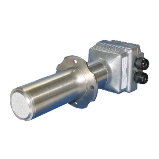
QGO21.000Dx7
Oxygen Sensor QGO21...
Basic Documentation
CC1P7845en
06.12.2017
The QGO21 and this Basic Documentation are intended for use by OEMs which
integrate the oxygen sensor in their products!
Note!
The QGO21 may only be operated with the following system components:
Type
from software version
AZL52...
04.90
LMV52.2...
05.00
LMV52.4...
10.10
PLL52...
01.50
QGO21 must be selected as the O2 sensor in the O2 module.
Building Technologies Division
Advertisement
Table of Contents

Related Manuals for Siemens QGO21 Series


Summary of Contents for Siemens QGO21 Series
- Page 1 QGO21.000Dx7 Oxygen Sensor QGO21... Basic Documentation The QGO21 and this Basic Documentation are intended for use by OEMs which integrate the oxygen sensor in their products! Note! The QGO21 may only be operated with the following system components: Type from software version AZL52…...
-
Page 2: Supplementary Documentation
Supplementary documentation Basic Documentation LMV5 ..................P7550 User Manual LMV52 ....................A7552 Mounting Instruction QGO21............M7845 (4 319 0866 0) 2/27 Building Technologies Division Oxygen Sensor QGO21... CC1P7845en Weishaupt 06.12.2017... -
Page 3: Table Of Contents
Contents Supplementary documentation ..................2 Safety notes ..................... 4 Warning notes ....................4 Engineering notes .................... 6 Installation and mounting notes ............... 6 Electrical connection ..................7 Commissioning notes .................. -
Page 4: Safety Notes
Safety notes 1.1 Warning notes To avoid injury to persons, damage to property or the environment, the following warning notes must be observed! It is not permitted to open the sensor incorrectly, interfere with or make changes to the sensor! ... - Page 5 The sensor must always be installed so that the connecting part (head to the flange) remains free and that unimpeded air exchange through the reference air slots is guaranteed. Otherwise, there is a risk of false measurements, which can lead to dangerous conditions ...
-
Page 6: Engineering Notes
1.2 Engineering notes If the burner is shut down for no more than 1 or 2 days, do not switch off the QGO21 and the associated control unit (LMV52 with PLL52) To ensure a good response, always use the QGO21 together with the AGO21 ... -
Page 7: Electrical Connection
1.4 Electrical connection It is important to achieve practically disturbance- and loss-free signal transmission: Never run the sensor cable together with other cables; use a separate cable Observe the permissible length of the sensor cables and the relevant specification (see Technical data) 7/27 Building Technologies Division... -
Page 8: Commissioning Notes
1.5 Commissioning notes To prevent the collection of condensate inside the QGO21, do not put the burner into operation before the sensor’s heating up phase is completed During the sensor’s heating up phase, temperature differences between the inner and outer electrode generate thermo-electric voltages which, in that phase, falsify the acquired oxygen value. - Page 9 After the final mounting check, a first functional check can be made: Functional check Before commissioning for the first time or after replacing the QGO21, the QGO21 must be checked for temporary O2 measured value distortion. The QGO21 must measure the O2 value with sufficient accuracy before an O2 setpoint curve is set.
-
Page 10: Standards And Certificates
ISO 14001:2015 OHSAS 18001:2007 China RoHS Hazardous substances table: http://www.siemens.com/download?A6V10883536 1.7 Service notes After no more than 3 months of operation following commissioning, check the sensor’s internal resistance. If it exceeds 30 , shorter the service interval to 3 months. Sensors having an internal resistance of >100 ... -
Page 11: Disposal Notes
1.8 Disposal notes The oxygen sensor contains electrical and electronic components and must not be disposed of together with household waste. Local and currently valid legislation must be observed. 11/27 Building Technologies Division Oxygen Sensor QGO21... CC1P7845en 1 Safety notes 06.12.2017... -
Page 12: Overview
Overview The QGO21 is an oxygen sensor that is used to acquire the residual oxygen content of flue gases in heat generating plants that heavy oil. The oxygen sensor works as a diffusion sensor with a sintered filter for the flue gas inlet. In connection with the control unit (LMV52 with PLL52), QGO21 monitors and controls the combustion process. -
Page 13: Assortment Connections
Assortment connections Article no. Type Oxygen sensor, complete with flange gasket - AC 230 V BPZ:QGO21.000D27 QGO21.000D27 - AC 120 V BPZ:QGO21.000D17 QGO21.000D17 Control unit for measurement of the rest of oxygen - LMV52 with PLL52 - See Basic Documentation P7550 Mounting flange for QGO21 BPZ:AGO21.000A AGO21.000A... -
Page 14: Technical Data
Technical data QGO21 Operating voltage of measuring cell’s - QGO21.000D27 AC 230 V ±15% AC 120 V 15% (only with LMV52 and - QGO21.000D17 PLL52) Mains frequency 50/60 Hz ±6% Power consumption Max. 90 W, typically 45 W (controlled) Perm. mounting position Refer to Mounting Instructions M7845 (74 319 0866 0) Degree of protection... -
Page 15: Description Of Functions
Description of functions 5.1 Functioning principle of the measuring cell The measuring cell of the QGO21 is made of ceramics (ZrO ) stabilized with Y At temperatures above 500 °C, oxygen ions can diffuse through the ceramics material. It carries a porous platinum layer on both sides, which serve as electrodes. Figure 2: Functioning principle of the measuring cell The diffusion of ions starts when concentrations on both sides of the cell differ. - Page 16 that is = = 21.5 4 x F R x T = 20.9 mV at T = 700 °C = 973 K 4 x F Figure 3: Nernst voltage as a function of the oxygen concentration at a cell temperature of 700 °C 16/27 Building Technologies Division Oxygen Sensor QGO21...
-
Page 17: Impact Of The Cell's Temperature
5.2 Impact of the cell’s temperature The slope of the curve changes on a change of cell temperature. The lower the temperature, the lower the Nernst voltage and the higher the displayed oxygen concentration. The higher the temperature, the higher the Nernst voltage and the lower the displayed oxygen concentration. -
Page 18: Impact Of The Reference Gas
5.3 Impact of the reference gas When the oxygen concentration of the reference gas changes, the point of intersection of the straight line with the abscissa will change (20.9%). Figure 5: Nernst voltage as a function of the reference gas ... -
Page 19: Mechanical Design Of The Sensor
Mechanical design of the sensor The function of the oxygen sensor is ensured by the following components: 1) Thermocouple The thermocouple acquires the temperature in the cell and delivers a signal of about 40 µV/K, which is used for temperature control. 2) Flue gas guidance Exchanges the measurement gases in the measuring cell area. -
Page 20: Mounting And Connecting The Sensor
Mounting and connecting the sensor 7.1 Mounting To simplify mounting in the chimney, AGO21 mounting flange is available. For mounting position, refer to Mounting Instructions M7845 (74 319 0866 0). The AGO21... must only be installed horizontally (Figure 7). Figure 7: Mounting position of QGO21 20/27 Building Technologies Division Oxygen Sensor QGO21... -
Page 21: Connection
7.2 Connection Figure 8 shows the connection of the QGO21 to the PLL52 Note The signal lines require shielded 6-core cables with twisted pairs. The shielding is to be connected to terminal GND of the PLL52. Open the cover only when the main switch is off so that both live and neutral conductors are disconnected ... -
Page 22: Connection Diagram
Connection diagram QGO21... B1 M B1 M B2 M G2 U3 PLL52... Figure 9: Connection diagram Legend (+) Signal of oxygen measuring cell (+) Thermocouple voltage Supply temperature compensation element Electrical ground for shielding Electrical ground for signals B1 and B2 Sensor heating with mains connection Sensor heating with mains connection (+) Signal of temperature compensation element... -
Page 23: Dimensions
Dimensions Dimensions in mm QGO21.000Dx7 7845m01/0812 2x Pg9 Figure 10: Dimension QGO21.000Dx7 Legend Sensor head Reference air slots Flange gasket (included) Sinter filter AGO21... 7845m02/1111 Figure 11: Dimension AGO21... AGO742870012 11,2 SW41 Figure 12: Dimension AGO742870012 23/27 Building Technologies Division Oxygen Sensor QGO21... -
Page 24: Comparison Table
10 Comparison table 7845z04e/1112 Figure 13: Comparison table for different flue gas analysis devices (in %)! Note! Additional humidity is not taken into account and may distort the measured value. Example: Urea injection. 24/27 Building Technologies Division Oxygen Sensor QGO21... CC1P7845en 10 Comparison table 06.12.2017... -
Page 25: List Of Figures
11 List of figures Figure 1: Example General overview ................12 Figure 2: Functioning principle of the measuring cell ............ 15 Figure 3: Nernst voltage as a function of the oxygen concentration at a cell temperature of 700 °C ........................ 16 ... -
Page 26: Index
12 Index A Mechanical design of the sensor ......19 Assortment connections ........13 Mounting and connecting the sensor ....20 C Connection ............21 Comparison table ............ 24 Mounting ............20 Connecting head ............19 O Connection diagram ..........22 Overview .............. - Page 27 Siemens AG Building Technologies Division © 2017 Siemens AG Building Technologies Division Berliner Ring 23 Subject to change! D-76437 Rastatt Tel. +49 7222 598-279 Fax +49 7222 598-269 www.siemens.com 27/27 Building Technologies Division Oxygen Sensor QGO21... CC1P7845en 12 Index 06.12.2017...