Table of Contents
Advertisement
Quick Links
READ AND SAVE THESE INSTRUCTIONS
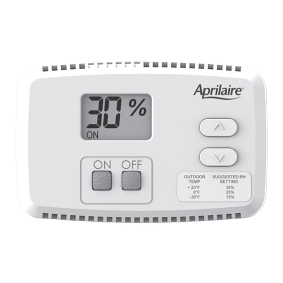
The Model 65 is for use with any humidifier
requiring an ON/Off signal for a 24 volt circuit.
SAfETy INSTRUCTIONS
1. Improper installation may cause property damage or injury. Installation, service,
and maintenance must be performed by a qualified service technician.
2. 120 Volts may cause serious injury from electric shock. Disconnect electrical
power before starting installation or servicing. Leave power disconnected until
installation/service is completed. This control is not a 120 Volt (line voltage)
device.
1. Read all instructions before beginning installation.
2. Do not adjust humidity set-point above recommended level or to recommended
level if condensation occurs on inside surface of windows or on other surfaces.
Excess condensation can cause damage to structure or furnishings. Excess
moisture can also allow the possibility for mold growth to occur.
3. Do not use solvents or cleaners on or near the display and circuit board.
Chemicals can damage components.
61000790B AA Model 65 Humidifier Control Install.indd 1
Model 65 Humidifier Control
Installation Instructions
WARNING
CAUTION
1
10/12/11 9:47 AM
Advertisement
Table of Contents

Related Manuals for Aprilaire 65


Summary of Contents for Aprilaire 65
-
Page 1: Safety Instructions
Model 65 Humidifier Control Installation Instructions READ AND SAVE THESE INSTRUCTIONS The Model 65 is for use with any humidifier requiring an ON/Off signal for a 24 volt circuit. SAfETy INSTRUCTIONS WARNING 1. Improper installation may cause property damage or injury. Installation, service, and maintenance must be performed by a qualified service technician. -
Page 2: Table Of Contents
. The control allows the homeowner to set and adjust the humidity setting and turn the humidifier on or off from a convenient location . The Model 65 uses an onboard sensor to monitor the relative humidity in the space in which it is located and displays the measured relative humidity on the digital display . -
Page 3: Materials Provided
• A pproximately 5’ off the floor. appliances that give off heat . • A t least 18” from an outside wall. • O n an outside or unconditioned area wall. See figure 1 . • I n stairwells or near outside doors. • O n a wall with concealed pipes or ductwork. fIGURE 1 – Mounting location 90-1666 61000790B AA Model 65 Humidifier Control Install.indd 3 10/12/11 9:47 AM... -
Page 4: Installation
. Failure to seal the opening may result in inaccurate operation due to drafts . fIGURE 2 – Disassemble Control BACK PLATE FRONT COVER RH SETTING LABEL 90-1667 61000790B AA Model 65 Humidifier Control Install.indd 4 10/12/11 9:47 AM... -
Page 5: Wiring
1 . Disconnect power to the humidifier and HVAC system . 2 . Connect the C and R terminals on the Model 65 to the HVAC or thermostat C and R terminals . 3 . Connect Model 65 H terminals to the humidifier solenoid valve control circuit as shown . - Page 6 4 – Recommended Wiring for Model 65 Control and Evaporative Humidifier HVAC EQUIPMENT MODEL 65 CONTROL ACCESSORY TERMINALS APRILAIRE EVAPORATIVE HUMIDIFIER SOLENOID VALVE CIRCUIT WIRES 90-1669 fIGURE 5 – Alternate Wiring for Model 65 Control and Evaporative Humidifier HVAC EQUIPMENT...
- Page 7 WIRING – Model 65 with Model 800 Steam Humidifier The Model 65 control requires 24VAC . See figure 6 . 1. D isconnect power from the Model 800 and HVAC system. 2 . Connect 24VAC to the C and R terminals on the Model 65 . 3. C onnect the H terminals on the Model 800 to the H terminals on the Model 65. 4. S nap the Model 65 front cover on the back plate. The 4-pin terminal aligns with the terminal block receptacle on the back plate.
- Page 8 7 – Recommended Wiring for Model 65 Control and Model 800 Steam Humidifier with Model 850 fan Pack MODEL 65 DIGITAL CONTROL 24VAC TRANSFORMER 24VAC TAP CONNECTORS CIRCUIT BOARD MODEL 850 STEAM HUMIDIFIER FAN PACK TRANSFORMER WIRE – 18 AWG ACCEPTABLE FOR 24 VAC APPLICATION.
-
Page 9: System Checkout
POWER UP 1. C heck all wiring. 2 . Restore power to the HVAC system and humidifier . 3 . After a 4 second start up sequence all buttons on the Model 65 will be functional . • T he control will be OFF. • T he humidity setting will be 30%. -
Page 10: Test Mode
-5% RH and +5% RH . 90-1638 • T he control will return to Normal Mode, displaying the measured humidity, 5 seconds after the last button press/release . 61000790B AA Model 65 Humidifier Control Install.indd 10 10/12/11 9:47 AM... -
Page 11: Turning On And Setting Control
Error Mode . Cycling power to the control will not clear the code and the control 90-1645 will need to be replaced . 61000790B AA Model 65 Humidifier Control Install.indd 11 10/12/11 9:47 AM... -
Page 12: Troubleshooting Guide
. P.O. Box 1467 • Madison, WI 53701-1467 • Phone: 800/334-6011 • Fax: 608/257-4357 www.aprilairepartners.com 61000790 10 .11 Printed in U .S .A . B2205457B © 2011 Aprilaire – A division of Research Products Corporation 61000790B AA Model 65 Humidifier Control Install.indd 12 10/12/11 9:47 AM...