Table of Contents
Advertisement
Quick Links
LINK BRIDGE™ 18G/4K HDMI SIGNAL
GENERATOR & ANALYZER
LB-H2-SGA
LB-H2-SGA
USER MANUAL
BCI reserves the right to make changes to the products described herein without
prior notice or consent. No liability is assumed as a result of their use or application.
All rights reserved.
©2020 Broadata Communications, Inc.
Advertisement
Table of Contents

Summary of Contents for Broadata LINK BRIDGE LB-H2-SGA
- Page 1 LB-H2-SGA LB-H2-SGA USER MANUAL BCI reserves the right to make changes to the products described herein without prior notice or consent. No liability is assumed as a result of their use or application. All rights reserved. ©2020 Broadata Communications, Inc.
- Page 2 SAFETY INSTRUCTIONS AND COMPLIANCE DECLARATION PLEASE OBSERVE THE FOLLOWING SAFETY PRECAUTIONS SURGE PROTECTION DEVICE RECOMMENDED This product contains sensitive electrical components that may be damaged by electrical spikes,surges,electric shock,lightning strikes, etc. Use of surge proctection system is highly recommended in order to protect and extend the life of your equipment.
-
Page 3: Table Of Contents
TABLE OF CONTENTS PRODUCT DESCRIPTION OPERATION CONTROL AND FUNCTIONS FRONT/REAR PANEL OLED SCREEN SIDE PANEL REMOTE CONTROL RS-232 PROTCOL & TELNET COMMANDS TELNET CONTROL OSD MENU TEST TIMINGS TEST PATTERNS SPECIFICATIONS REPLACEMENT POLICY RETURN AND REPAIR SERVICE LIMITED WARRANTY Link Bridge™ Signal Generator and Analyzer User Manual (LB-H2-SGA) -
Page 4: Product Description
PRODUCT DESCRIPTION The 18G/4K HDMI 2.0 Signal Generator & Analyzier is a must-have for all AV System Integrators and Technicians. It is the ideal diagnostic tool for the design, testingm troubleshooting and repair of various source and sink devices. The ability to generate various audio and video signal provides you with the flexibility to easily and accurately diagnose and test various HDMI Video and Audio equipment. -
Page 5: Operation Control And Functions
OPERATION CONTROL AND FUNCTIONS FRONT PANEL No Signal 5V=0 CKDT=0 SCDT=0 ENTER MENU OPTION EDID HDCP COLOR TIMING PATTERN PATTERN PATTERN SPACE AUDIO HDCP DEEP OUTPUT ANALYSER LPCM ON/OFF COLOR FORMAT /PATTERN FACTORY RESET OLED Screen: Displays the current signal analysis information or test pattern mode selection details including input and/or output resolution timing. - Page 6 OPERATION CONTROL AND FUNCTIONS FRONT PANEL (CON’T) No Signal 5V=0 CKDT=0 SCDT=0 ENTER MENU OPTION EDID HDCP COLOR TIMING PATTERN PATTERN PATTERN SPACE AUDIO DEEP OUTPUT HDCP ANALYSER LPCM COLOR FORMAT ON/OFF /PATTERN FACTORY RESET TIMING: Press to enable selection of the output timing and resolution used. The buttons will illuminate and are used to select the new timing.
- Page 7 OPERATION CONTROL AND FUNCTIONS FRONT PANEL (CON’T) No Signal 5V=0 CKDT=0 SCDT=0 ENTER MENU OPTION EDID HDCP COLOR TIMING PATTERN PATTERN PATTERN SPACE AUDIO DEEP OUTPUT HDCP ANALYSER LPCM ON/OFF COLOR FORMAT /PATTERN FACTORY RESET EDID PATTERN: Press to enable selection of the EDID to use on the HDMI input port.
- Page 8 OPERATION CONTROL AND FUNCTIONS FRONT PANEL (CON’T) No Signal 5V=0 CKDT=0 SCDT=0 ENTER MENU OPTION EDID HDCP COLOR TIMING PATTERN PATTERN PATTERN SPACE AUDIO HDCP DEEP OUTPUT ANALYSER LPCM ON/OFF COLOR FORMAT /PATTERN FACTORY RESET HDCP ON/OFF: Press to switch between supported HDCP versions or to disable HDCP.
-
Page 9: Oled Screen
OPERATION CONTROL AND FUNCTIONS OLED Screen: Analyzer Mode (Analyzer/Pattern button is RED): In Analyzer mode, if there is no live video source detected on the input port, the OLED will display an voltage, TMDS or sync that might be present. Once a live video signal is detected, the unit will display that signal’s current timing, format, HDCP version, AV Mute status, color space, color depth and audio format. - Page 10 OPERATION CONTROL AND FUNCTIONS Pattern Mode (Analyzer/Pattern button is BLUE): In Pattern mode, when the output isn’t connected to a sink, the unit will display the current output timing, RX Sense, and Hot- plug detection status. Once an active sink has been connected, the lower portion of the display will change to indicate the current test pattern number and name.
-
Page 11: Side Panel
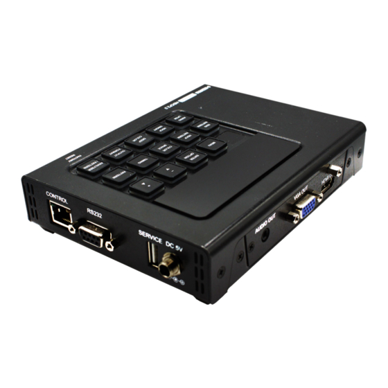
OPERATION CONTROL AND FUNCTIONS SIDE PANEL A AUDIO OUT VGA OUT HDMI OUT AUDIO OUT: Connect to powered speakers or an amplifier for stereo analog audio output with a 3.5mm phone jack cable. VGA OUT: Connect to a VGA (RGB) monitor or display for analog video output. HDMI OUT: Connect to HDMI TVs, monitors or amplifiers for digital video and audio output. - Page 12 OPERATION CONTROL AND FUNCTIONS SIDE PANEL C POWER POWER: Flip this switch to turnthe unit ON or OFF after connecting an approproate power source. SIDE PANEL D SERVICE DC 5V CONTROL RS-232 CONTROL: Connect directly, or through a network switch, to your PC/laptop to control the unit via Telnet.
- Page 13 OPERATION CONTROL AND FUNCTIONS REMOTE CONTROL Analyzer/Pattern Press to switch between Analyzer Mode and Pattern Mode EDID: Press repeatedly to switch between the available EDIDs for the HDMI input Color Space: Press repeatedly to space formats (RGB, YCbCr 4:4:4, YCbCr 4:2:2 and YCbCr 4:2:0) HDCP SW: Press to switch between supported HDCP versions or to disable...
-
Page 14: Remote Control
OPERATION CONTROL AND FUNCTIONS REMOTE CONTROL (CON’T) T-T+: Press (+/-) to select a new output resilution timing. Within the OSD menu, press to adjust selections. P+P-:: Press (+/-) to change the current test pattern. Within the OSD menu, press to move up and down. After selecting a pattern, press and hold for 2 seconds to switch to alternate variations of the pattern. -
Page 15: Rs-232 Protcol & Telnet Commands
RS-232 PROTOCOL & TELNET COMMANDS UNIT (DCE*) SERIAL PORT SETTINGS Pinout Baud Rate 115200 Data Bits Parity Bits None Stop Bits Flow Control None Termination CR (xoD) * DCE: Data Communications Equipment Link Bridge™ Signal Generator and Analyzer User Manual (LB-H2-SGA) - Page 16 RS-232 PROTOCOL & TELNET COMMANDS COMMANDS DESCRIPTION VARIABLES Show full command list. $HELP Show full command list. $AUDIO_CH N1 Set the number of internally Available values for N1: sourced audio output channels. 2 [2 Channels (2.0)] 6 [6 Channels (5.1)] 8 [8 Channels (7.1)] $AUDIO_CH? Display the current number of audio...
- Page 17 RS-232 PROTOCOL & TELNET COMMANDS COMMANDS DESCRIPTION VARIABLES $AUDIO_MUTE N1 Turn the audio output mute on or off. N1 = ON, OFF $AUDIO_MUTE? Display the audio output mute state. $AUDIO_SOURCE N1 Available values for N1: ANA [Analog Input] Set the audio output source. HDMI [HDMI Input] INT [Internal] $AUDIO_SOURCE?
- Page 18 RS-232 PROTOCOL & TELNET COMMANDS COMMANDS DESCRIPTION VARIABLES $CED_UPDATE_COUNT? Response: $ced_update_count? Gets the CED_update flag count hh:mm:ss,count $COLOR_SPACE N1 Available values for N1: Y444 [YCbCr 4:4:4] Set the output color space. Y422 [YCbCr 4:2:2] Y420 [YCbCr 4:2:0] $COLOR_SPACE? Display the current output color $DEEP_COLOR N1 Set the output color bit depth.
- Page 19 RS-232 PROTOCOL & TELNET COMMANDS COMMANDS DESCRIPTION VARIABLES $CED_UPDATE_COUNT? Response: $ced_update_count? Gets the CED_update flag count hh:mm:ss,count $COLOR_SPACE N1 Available values for N1: RGB [RGB 4:4:4] Set the output color space. Y444 [YCbCr 4:4:4] Y422 [YCbCr 4:2:2] Y420 [YCbCr 4:2:0] $COLOR_SPACE? Display the current output color $DEEP_COLOR N1...
- Page 20 RS-232 PROTOCOL & TELNET COMMANDS COMMANDS DESCRIPTION VARIABLES If the EDID fails to be read, “$err_ddc” will be displayed. If the EDID has invalid content, “$err_bad” will be displayed. $EDID_NAME N1,N2 N1 = C1 ~ C10 Set the EDID name of the selected copy slot.
- Page 21 RS-232 PROTOCOL & TELNET COMMANDS COMMANDS DESCRIPTION VARIABLES If the EDID fails to be read, “$err_ddc” will be displayed. If block 2 or block 3 doesn’t exist, “$err_block” will be displayed. $EDID_RX N1 Select the EDID to use with the Available values for N1: unit’s HDMI input (Rx).
- Page 22 RS-232 PROTOCOL & TELNET COMMANDS COMMANDS DESCRIPTION VARIABLES $FACTORY Execute a factory reset and reboot the unit. Stored Copy EDIDs and Ethernet settings will not be reset. $FWVER? Display the current firmware version. $HDCP_IN_SW N1 Enable or disable HDCP support for N1 = ON, OFF Affects Analyzer mode only.
- Page 23 RS-232 PROTOCOL & TELNET COMMANDS COMMANDS DESCRIPTION VARIABLES $HDCP_OUT_SW? Display the HDMI output’s HDCP sta- tus. A status of “Talk” means HDCP is currently performing handshaking. $HDCP_OUT_VER N1 Available values for N1: Set the HDCP version to use on the V1.4 [HDCP v1.4] unit’s HDMI output.
- Page 24 RS-232 PROTOCOL & TELNET COMMANDS COMMANDS DESCRIPTION VARIABLES $HDR_MFALL N1 Set the maximum HDR frame- N1 = 0 ~ 65500 [100 unit average light level. increments] $HDR_MFALL? Display HDR maximum light level of frame-average. $HDR_SET N1 Select the current HDR setting. N1 = 1 ~ 3 $HDR_SET? Display the current HDR setting.
- Page 25 RS-232 PROTOCOL & TELNET COMMANDS COMMANDS DESCRIPTION VARIABLES $MODEL? Display the unit’s model number. $MOTION_TEXT N1 Set the text used for the Motion-H N1 = {Text} [20 characters max] and Motion-V patterns. $MOTION_TEXT? Display the current text used for the $NET_GATE? Display the current Gateway address.
- Page 26 RS-232 PROTOCOL & TELNET COMMANDS COMMANDS DESCRIPTION VARIABLES $NET_STATIC_GATE N1 Set the static Gateway address. N1 = X.X.X.X [X = 0 ~ 255] $NET_STATIC_GATE? Display the static Gateway address. $NET_STATIC_IP N1 Set the static IP address. N1 = X.X.X.X [X = 0 ~ 255] $NET_STATIC_IP? Display the static IP address.
- Page 27 RS-232 PROTOCOL & TELNET COMMANDS COMMANDS DESCRIPTION VARIABLES $RX_HOTPLUG? Display the current hot plug state for the HDMI input (Rx). $RX_HOTPLUG_T N1 Set the hot plug time (in milliseconds) N1 = 50 ~ 500 [50ms increments] for the HDMI input (Rx). $RX_HOTPLUG_T? Display the current hot plug time (in milliseconds) for the HDMI input (Rx).
- Page 28 RS-232 PROTOCOL & TELNET COMMANDS COMMANDS DESCRIPTION VARIABLES $SINK_DETECT? N1 Displays a variety of sink detection Available values for N1: See below. HOTPLUG [Sink’s hot plug status] RSENSE [Sink’s RxSense status] HDCP [Sink’s HDCP port status] HDCP_AKSV [Source HDCP AKSV in 2-digit hex (HDCP v1.4)] HDCP_ SCDC_SCR_ENABLE [Rx SCDC source scrambling setting] SCDC_SCR_ SCDC_SOURCE_VER [SCDC source version] $SOURCE_DETECT? N1...
- Page 29 RS-232 PROTOCOL & TELNET COMMANDS COMMANDS DESCRIPTION VARIABLES PIXEL_CLOCK [Pixel clock in kHz] SCAN [Video scan mode (P = Progressive, I = Interlaced)] TIMING [Video timing (See “Source Video Timing List” below)] TMDS_CLOCK [TMDS clock in kHz] VA [Vertical active lines] VBP [Vertical back porch lines] VFP [Vertical front porch lines] VSW [Vertical sync width lines]...
- Page 30 RS-232 PROTOCOL & TELNET COMMANDS COMMANDS DESCRIPTION VARIABLES $TASK_MODE N1 Available values for N1: Set the unit’s operation mode to Sig- ANALYSER [Analyzer Mode] nal Analyzer or Pattern Generation. PATTERN [Pattern Mode] $TASK_MODE? Display the unit’s current operation $TIMING N1 Available values for N1: 1 ~ 91 [All available standard Select the output resolution timing to...
- Page 31 RS-232 PROTOCOL & TELNET COMMANDS COMMANDS DESCRIPTION VARIABLES $TX_5V N1 Available values for N1: Set the unit’s output +5V pin state to FOLLOW [Only output 5V if follow the TMDS output state or to there is a live signal] always be on. ON [Always output 5V] $TX_5V? Display the current output +5V pin...
-
Page 32: Telnet Control
TELNET CONTROL Before attempting to use telnet control, please ensure that both the unit and the PC/Laptop are connected to the same active networks. To access Telnet in Windows 7, click on the “Start” menu and type “cmd” in the search field, then press “Enter”. - Page 33 TELNET CONTROL This will connect us to the unit we wish to control. Type “$help” or “$?” to list the avail- able commands. NOTE: NOTE: • • ALL COM- ALL COM- MANDS MUST MANDS MUST START WITH THE START WITH THE “$”...
-
Page 34: Osd Menu
OSD MENU ANALYZER MODE LEVEL 1 LEVEL 2 LEVEL 3 SOURCE MONITOR [ANALYTIC DATA] VIDEO TIMING [ANALYTIC DATA] AUDIO TIMING [ANALYTIC DATA] PACKET MONITOR [ANALYTIC DATA] VSIF H14B DRMI (HDR) NOTE: NOTE: EDID ANALYZER HDMI SINK VGA SINK [ANALYTIC DATA] •... - Page 35 OSD MENU ANALYZER MODE LEVEL 1 LEVEL 2 LEVEL 3 EDID EMULATOR COPY HDMI SINK EDID TO [C1 COPY HDMI SINK EDID ~ 10] COPY VGA SINK EDID TO [C1 COPY VGA SINK EDID ~ 10] RENAME COPIED RENAME EDID [C1 ~ 10] SINK EDID BURN EDID [D1 ~ 10] &...
- Page 36 OSD MENU ANALYZER MODE LEVEL 1 LEVEL 2 LEVEL 3 RX PORT HDCP REAUTH_ CONTROLS REQ TOGGLE HDCP COUNTER RESET RX PORT SCDC PORT *POR CONTROLS SCDC CED CH AUTO CLEAR AUTO CLEAR WHILE SOURCE READS CED. OUTPUT SEE “TEST TIMING RESOLUTION LIST”...
- Page 37 OSD MENU ANALYZER MODE LEVEL 1 LEVEL 2 LEVEL 3 SETUP FIRMWARE UPDATE NO/YES IMAGE 640×480 UPDATE NO/YES IMAGE 1920×1080 NO/YES UPDATE SMALL [LETTER H] OPTION 2 MEDIUM 3D SOURCE NO/YES IMAGE BYPASS 1 SEC ~ 2 SEC (2 SEC) INFORMATION REFRESH NOTE: NOTE:...
- Page 38 OSD MENU • Unit HDR Capabilities & Limitations: Support HDR bypass & analysis in Analyzer mode. HDR EDID must be copied from an connected sink to the RX EDID through the EDID Emulator menu in Analyzer mode. EDID Analyzer & DRMI Packet Monitor for HDR analysis in Analyzer mode. Output emulated HDR metadata to test sink HDR detection in Pattern mode.
- Page 39 OSD MENU PATTERN MODE LEVEL 1 LEVEL 2 LEVEL 3 SINK MONITOR [ANALYTIC DATA] PATTERN SEE “TEST PATTERN LIST” BELOW (P16 COLORBAR S.) AUDIO OUTPUT HDMI IN SOURCE ANALOG IN *POR INT. SINEWAVE VOLUME 0 ~ 80 (70) SD0 L/R SD1 L/R NOTE: NOTE:...
- Page 40 OSD MENU PATTERN MODE LEVEL 1 LEVEL 2 LEVEL 3 HDR OUTPUT SETTINGS 1 ~ 3 (1) EMULATOR VALUE UNIT NIT (CD/M*M) NO DATA ITU601 ITU709 XVYCC601 XVYCC709 TX AVI COLORIMETRY SYCC601 ADOBE Y601 NOTE: NOTE: ADOBE RGB BT.2020 (1) •...
- Page 41 OSD MENU PATTERN MODE LEVEL 1 LEVEL 2 LEVEL 3 SCDC OUTPUT [ANALYTIC DATA] MONITOR TX PORT CONTROLS FOLLOW TMDS +5V OUT ON/OFF ALWAYS ON HDCP OUTPUT ON/OFF *POR HDCP OUTPUT VERSION V2.2 HDCP AKE_SEND_ NOTE: NOTE: STORED_ KM() HDCP COUNTER RESET •...
- Page 42 OSD MENU PATTERN MODE LEVEL 1 LEVEL 2 LEVEL 3 P MODE COLOR OSD SETTINGS BLUE (PATTERN MODE ONLY) BLACK DHCP IP MODE STATIC IP ADDRESS X.X.X.X (192.168.1.50) ETHERNET SUBNET MASK X.X.X.X (255.255.255.0) GATEWAY X.X.X.X (192.168.1.254) NOTE: NOTE: FIRMWARE UPDATE NO/YES IMAGE 640×480 UPDATE NO/YES...
- Page 43 OSD MENU TEST PATTERN NAME VARIATIONS TEST PATTERN NAME VARIATIONS ID BORDER GRAYSCALE 64 CHECKERBOARD GRAYSCALE 256 CIRCLE 1 GRAYSCALE 256RGB CIRCLE 4 GRAYSCALE ADJUST BLACK GRAYSCALE H BLUE GRID CYAN IMAGE GREEN LETTER H MAGENTA LINE ON/OFF-H NOTE: NOTE: LINE ON/OFF-V •...
- Page 44 OSD MENU TEST TIMING LIST TEST TIMING LIST HZ 1080I 3840×2160P 1080P NOTE: NOTE: • • ALL COM- ALL COM- MANDS MUST MANDS MUST 4096×2160P START WITH THE START WITH THE “$” CHARACTER “$” CHARACTER 2048×1080P OR THE COM- OR THE COM- MAND WILL NOT MAND WILL NOT AUTO NATIVE...
-
Page 45: Test Timings
TEST TIMINGS INPUT VERTICAL FREQUENCY (HZ) PC RESOLUTION HDMI HDMI 640×350P ✓ ✓ ✓ ✓ 640×480P 59, 72, 75, 85 ✓ ✓ ✓ ✓ 720×400P 70, 85 ✓ ✓ ✓ ✓ 800×600P 56, 60, 72, 75, 85 ✓ ✓ ✓ ✓... - Page 46 TEST TIMINGS Note: • RB=Reduced Blanking • 87 total resolutions. • VGA output limitations: - Only supports RGBHV. (No YUV, RGBS or RGB support) - In Analyzer mode: VGA output is turned off. - In Pattern mode: VGA output has limited resolution support. - OSD Menu display is not supported.
-
Page 47: Test Patterns
TEST PATTERNS TEST PATTERN NAME VARIATIONS TEST PATTERN NAME VARIATIONS BORDER GRAYSCALE 64 CHECKERBOARD GRAYSCALE 256 CIRCLE 1 GRAYSCALE 256RGB CIRCLE 4 GRAYSCALE ADJUST 256 BLACK GRAYSCALE H BLUE GRID CYAN IMAGE GREEN LETTER H MAGENTA LINE ON/OFF-H NOTE: NOTE: LINE ON/OFF-V •... - Page 48 TEST PATTERNS BORDER NOTE: NOTE: • • ALL COM- ALL COM- The Border pattern presents 4 equal-sized squares dividing the screen into 4 quadrants, MANDS MUST MANDS MUST forming a central white cross, with red, green, blue and white inner squares. Ideal for START WITH THE START WITH THE testing screen boundary, alignment and pincushion issues.
- Page 49 TEST PATTERNS CIRCLE 1 The Circle 1 pattern provides a single white circle in the middle with a white cross and a white outer border line. This pattern is designed for quickly confirming that the geometry of the scene is correct and that the full source is being displayed, edge to edge. NOTE: NOTE: •...
- Page 50 TEST PATTERNS CIRCLE 4 The Circle 4 pattern provides 4 smaller white circles in each of the 4 corners of the screen. This pattern can help confirm that the display is maintaining correct geometry at the edges of the screen. NOTE: NOTE: •...
- Page 51 TEST PATTERNS COLORBAR DISPLAY The Colorbar Delay pattern provides a sequence of standard 100% color bars with a full set of smaller color squares within each bar. This test is primarily to detect if any of the color components of the video signal are delayed/skewed relative to each other. Pay NOTE: NOTE: close attention to the left and right sides of the squares and look for a color shift.
- Page 52 TEST PATTERNS COLORBAR MOTION (2 VARIATIONS) Slow/Fast Motion NOTE: NOTE: The Colorbar Motion pattern is a standard (white, yellow, cyan, green, magenta, red, blue, black) 100% color bar pattern using vertical bars with a grey bar moving horizon- tally across it. There are 2 variations: slow and fast motion of the grey bar. •...
- Page 53 TEST PATTERNS COLORBAR SPLIT The Colorbar Split pattern is a vertical color bar pattern with the color bars split in the middle by large black and white sections. All colors (white, yellow, cyan, green, magenta, red, blue) are at 100% brightness. NOTE: NOTE: •...
- Page 54 TEST PATTERNS CROSS HATCH 8 (2 VARIATIONS) Normal Inverse NOTE: NOTE: The Cross Hatch 8 pattern is a full field black & white pattern of crossing vertical and horizontal lines dividing the screen into 8 sections in each direction. This pattern is primarily used to check for color convergence and pincushion issues in projectors.
- Page 55 TEST PATTERNS CROSS HATCH 32 (2 VARIATIONS) Normal Inverse NOTE: NOTE: The Cross Hatch 32 pattern is a full field black & white pattern of crossing vertical and horizontal lines dividing the screen into 32 sections in each direction. This pattern is •...
- Page 56 TEST PATTERNS DIAGONAL 2 NOTE: NOTE: The Diagonal 2 pattern is 2 diagonal lines that travel from the corners to the exact center of the display. This can be used to check for alignment and geometry issues, particularly • • ALL COM- ALL COM- with projectors.
- Page 57 TEST PATTERNS GENERAL (3 VARIATIONS) Stop/Slow/Fast Motion NOTE: NOTE: The General pattern is an all-purpose, multi-pattern test to visually check for multiple issues simultaneously. It includes color bars, 8-step grayscale, vertical and horizontal • • ALL COM- ALL COM- multi-burst, cross hatch, circle and motion patterns. There are 3 variations: No motion, slow motion and fast motion.
- Page 58 TEST PATTERNS GRAYSCALE 8 (3 VARIATIONS) Vert. Bar Vert. L/R Bar Hori. Bar NOTE: NOTE: The Grayscale 8 pattern provides a way to check and adjust the contrast, brightness and grayscale tracking of your display with 8 bars progressing from 0% to 100% brightness in •...
- Page 59 TEST PATTERNS GRAYSCALE 32 (3 VARIATIONS) Vert. Bar Vert. L/R Bar Hori. Bar NOTE: NOTE: The Grayscale 32 pattern provides a way to check and adjust the contrast, brightness and grayscale tracking of your display with 32 bars progressing from 0% to 100% brightness •...
- Page 60 TEST PATTERNS GRAYSCALE 256 (4 VARIATIONS) Gray Green Blue NOTE: NOTE: The Grayscale 256 pattern provides a way to fine tune the con- trast, brightness and grayscale tracking of your display with a full 265 step gradient progressing from 0% to •...
- Page 61 TEST PATTERNS GRAYSCALE ADJUST (256 VARIATIONS) Adjustable from 0 to 256 NOTE: NOTE: The Grayscale Adjust pattern provides a full field of grey with user adjustable brightness levels for testing display gray purity and signal response. The brightness can be freely •...
- Page 62 TEST PATTERNS GRAYSCALE 256 (4 VARIATIONS) NOTE: NOTE: The Grid pattern provides a selection of red, green, blue and white boxes with 2×2 grids within and above them to test for pixel on pixel and color offset issues. • • ALL COM- ALL COM- MANDS MUST...
- Page 63 TEST PATTERNS LETTER H (2 VARIATIONS) Big/Small H NOTE: NOTE: The Letter H pattern is a screen filled with a series of large capital “H” characters moving vertically up the screen. This is a basic test to confirm motion detail. There are 2 variations: •...
- Page 64 TEST PATTERNS LINE ON/OFF-V (2 VARIATIONS) Red & Green Lines White & Black Lines (Not Supported in 4K) NOTE: NOTE: The Line On/Off-V pattern generates an alternating pattern of single- pixel vertical lines. This pattern can be used to analyze the horizontal pixel resolution of your display. If the •...
- Page 65 TEST PATTERNS LINE ON/OFF-V (4K) White & Black Lines The Line On/Off-V 4K pattern generates an alternating pattern of single-pixel vertical lines. This pattern can be used to analyze the horizontal pixel resolution of your display. NOTE: NOTE: If the output appears to have mosaic patterns, or appears to be a solid field (grey, white or black), then it is possible that your display does not fully support the resolution you are •...
- Page 66 TEST PATTERNS MOTION-V (4 VARIATIONS) Slow/Fast RGB Block Slow/Fast Strong NOTE: NOTE: The Motion-V patterns are a collection of vertical motion tests. These can be used to test your display’s pixel on/off response time. There are 4 variations: Slow red/green/blue block, fast red/ green/block, slow moving sample text, fast moving sample text.
- Page 67 TEST PATTERNS NEEDLES NOTE: NOTE: The Needles pattern is a standard needle pulse test. The top half of the screen is black and the bottom half is white with 2 thin inverse- brightness lines crossing from top to bottom. This pattern allows for analysis of the sharpness, blooming and screen distortion •...
- Page 68 TEST PATTERNS PLUGE (2 VARIATIONS) Full/Limited RGB Range NOTE: NOTE: The Pluge pattern is used to perform the accurate and consistent brightness and contrast configuration of a display. Typically you will want to adjust the brightness control of the • •...
- Page 69 TEST PATTERNS SQUARE H8 (2 VARIATIONS) Inverse Normal NOTE: NOTE: The Square H8 pattern is a full field black & white pattern of squares dividing the screen horizontally into 8 sections. This pattern is primarily used to check projector linearity. There are 2 variations: Normal (white lines, black field) and Inverse (black lines, white •...
- Page 70 TEST PATTERNS SQUARE H32 (2 VARIATIONS) Inverse Normal NOTE: NOTE: The Square H32 pattern is a full field black & white pattern of squares dividing the screen horizontally into 32 sections. This pattern is primarily used to check projector linearity. There are 2 variations: Normal (white lines, black field) and Inverse (black lines, white •...
- Page 71 TEST PATTERNS WINDOW BLUE (4 VARIATIONS) Normal 75% Inverse 75% Normal 50% Inverse 50% WINDOW CYAN (4 VARIATIONS) NOTE: NOTE: • • ALL COM- ALL COM- MANDS MUST MANDS MUST Normal 75% Inverse 75% Normal 50% Inverse 50% START WITH THE START WITH THE “$”...
- Page 72 TEST PATTERNS WINDOW RED (4 VARIATIONS) Normal 75% Inverse 75% Normal 50% Inverse 50% WINDOW WHITE (4 VARIATIONS) NOTE: NOTE: • • ALL COM- ALL COM- MANDS MUST MANDS MUST Normal 75% Inverse 75% Normal 50% Inverse 50% Normal 50% Normal 75% Inverse 75% Inverse 50%...
-
Page 73: Specifications
SPECIFICATIONS INPUT/OUTPUT/CONTROL PORTS CERTIFICATIONS Input One- HDMI Input Port CE, FCC One- L/R analog audio (3.5mm jack) GREEN COMPLIANCE Output One- HDMI Output Port RoHS One- VGA Output Port, HD-15 One- L/R Analog Audio (3.5mm jack) ORDER INFORMATION VGA Output Resolution Support 350p, 480p, 576p, LB-H2-SGA LinkBridge™... -
Page 74: 5.1 Replacement Policy
If you have a problem with your unit, please contact the Customer Service Department. To facilitate our return/ repair processing please contact Broadata Communications, Inc. to obtain a Return Material Authorization (RMA). Please include the following information: • Product Model Number •... -
Page 75: Limited Warranty
LIMITED WARRANTY 6.0 LIMITED WARRANTY Broadata Communications, Inc. (BCI) warrants, for a period of one year from date of ship- ment, each product sold shall be free from defects in material and workmanship. BCI will correct, either by repair, or at BCI’s election, by replacement, any said products that in our sole discretion prove to be defective and are returned to the manufacturing location within 30 days after such defect is ascertained. - Page 76 Broadata Communications, Inc. 2545 West 237th Street, Suite K Torrance, CA 90505 1-800-214-0222 (310) 530-1416 (310) 530-5958 (Facsimile) e-mail: Sales@Broadatacom.com 2545 West 237th Street Website: www.broadatacom.com Torrance, CA 90505 800•214•0222 310•530•1416 e-mail: Sales@broadatacom.com www.broadatacom.com Link Bridge™ Signal Generator and Analyzer User Manual (LB-H2-SGA)- 60000LB-H2-SGA...