Table of Contents
Advertisement
Quick Links
SERVICE MANUAL
For Technical Service
Frequency range
Dimensions
Mass (weight)
RF power output
Operational temperature –22°F to +140°F (–30°C to +60°C)
Supplied accessories
Design and specifications are subject to change without notice.
Visit our web site @ http://www..sony.com/wireless
Confidential proprietary information contained within.
All rights reserved.
Sony Corporation PMC America
SPECIFICATIONS
Dual Mode, Dual Band (Amps Mode)
Transmit: 824.04 to 848.97 MHz
Receive:
869.04 to 893.97 MHz
Single Band, Dual Mode (CDMA/PCS)
Transmit: 1851.25 to 1908.75 MHz
Receive:
1931.25 to 1988.75 MHz
5.7 × 2.0 × 1.5 inches (h/w/d) (not including antenna)
(146 × 50 × 37 mm)
Approx. 7.2 oz (203 g) (including battery)
Dual Mode, Dual Band and Single Band
0.01 µW to 300 mW
CDMA:
FM:
6 mW to 600 mW
(Battery pack –10°C to +40°C)
QN-003BPLH Hi-Cap Li-Ion Battery pack (1)
QN-001AC AC Adapter (1)
Hand strap (1)
PORTABLE CELLULAR TELEPHONE
CM-Sx100
CM-Bx200
CM-Mx300
WITH ACCESSORIES
Advertisement
Table of Contents

Related Manuals for Sony CM-Sx100


Summary of Contents for Sony CM-Sx100
- Page 1 QN-003BPLH Hi-Cap Li-Ion Battery pack (1) QN-001AC AC Adapter (1) Hand strap (1) Design and specifications are subject to change without notice. Visit our web site @ http://www..sony.com/wireless PORTABLE CELLULAR TELEPHONE WITH ACCESSORIES Confidential proprietary information contained within. All rights reserved.
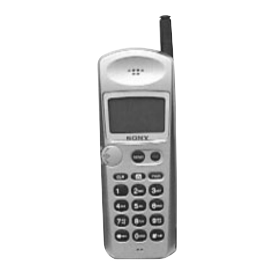
- Page 2 Looking at Your Phone (This section is extracted from instruction manual.) For further information, refer to the pages indicated in ( ) in the Owner’s Manual. 1 Antenna (16) 2 Earpiece 3 Display See “Display” for a general explanation of the items that appear on the display.
-
Page 3: Service Tools
SECTION 1 SERVICE TOOLS Figure Description Part # Audio Break-Out Box 3-702-707-01 Standard Test Jig DST-000-108 Service Support Tool (SST) 1-759-580-11 RF Connector, Standard Handset R-191-977-02 LCD Removal Tool WTC000016 Standard Handset Interface Cable DST-STD-104 Digital Service Tool (DST) DST-000-100 Standard Test Cable DST-000-107 Figure 1... -
Page 4: Table Of Contents
Table of Contents Service Tools ................. Section One Audio Break-Out Box Standard Test Jig SST (Service Support Software) RF Connector LCD Removal Tool Standard Handset Interface Cable DST (Digital Service Tool) Standard Test Cable Test Procedures ..............Section Two Hewlett Packard 8920B Hewlett Packard 8924C Tektronix CMD80 Level II Test Routine for HP8924C... -
Page 5: Test Procedures
SECTION 2 TEST PROCEDURES Testing a SONY CM-Mx300/CM-Bx200 (Analog Only) on a HP8920B Press the “POWER” key on the Handset and wait for The following pages illustrate how to set up and perform the Handset to power up. After the Handset has... - Page 6 SECTION 2 TEST PROCEDURES Handoffs Mute the microphone audio from the Handset by depressing and holding the "Jog Dial", set "De- Emphasis" to "OFF" and the "Detector" to RMS*SQRT2. Press the “K2” soft key on the front panel of the HP8920B to execute the “Chng Chan”...
- Page 7 "Echo". Select the "Echo Delay" field Testing a SONY CM-SX100/CM-BX200 (PCS Only) On a HP8924C/E and select "2 seconds". This sets up a 2 second delayed The following pages illustrate how to set up and perform PCS return loop allowing you to hear yourself talk into the Handset.
- Page 8 Talk into the microphone of the Handset. Your speech will be echoed back to you through the earpiece, confirming that the audio path of the Handset is working properly. Press the “END CALL” key in the “ CDMA CALL CONTROL” area on the front panel of the HP8924C/E to end the call.
- Page 9 SECTION 2 TEST PROCEDURES HP8920B “Test Screen” (Main Menu) TESTS (Main Menu) PER CALD Run Test Continue Help LOAD TEST PROCEDURE: Select Procedure Location: Select Procedure Filename: Library: Program: PER_CALD [NO LIB] To Screen Description: RF GEN Runs Periodic Calibration Programs for Cellular RF ANL Adapter.
- Page 10 SECTION 2 TEST PROCEDURES Inserting Handset into Standard Test Jig Slide Handset into the cradle and align to rear Slide Handset and locking collar backwards guide slots. until the Handset and Test Jig connectors mate. Depress the spring loaded latch and lower the Handset onto the RF Connector and lock in place.
- Page 11 SECTION 2 TEST PROCEDURES Audio Break-Out Box, Power Supply and RF Connections Connect the Power Supply to the Audio Break- Connect the RF Cable of the Standard Test Jig Out Box as shown above. to the RF IN/OUT port of the HP8920B as shown above.
- Page 12 SECTION 2 TEST PROCEDURES HP8920B “RF Generator Screen” RF GENERATOR TX Frequency AC Level 0.00010 TX Power SINAD 0.00000 0.23 RF Gen Freq AFGen1 Freq AFGen2 Freq Mic Pre-Enp To Screen 100.000000 1.0000 1.0000 Auto/Hold RF GEN On/Off RF ANL SPEC ANL SPEC ANL SPEC ANL...
- Page 13 The following pages illustrate how to set up and perform basic from the HP8924C/E, it will sense that it is in its Home System analog and digital cellular tests on a SONY CM-Mx300/CM- and you will see the RSSI indicator display a strong signal. If the Bx200 Handset.
- Page 14 “CALL CONTROL” the Handset’s active NAM, “MOBILE NETWORK screen. Change the voice channel as described in the CODE” value. See “Service Programming Sony’s CM- “Handoffs” section (steps 23 and 24). Repeat steps 27 Mx300 Handset” for more information.
- Page 15 Insert the Standard Test Cable between the Audio Break- Talk into the microphone of the Handset. Your speech Out Box connector and the base of the SONY CM-Mx300 will be echoed back to you through the earpiece, Handset as shown in Figure 1.
- Page 16 SECTION 2 TEST PROCEDURES Standard Test Jig Cable Connect the 15 pin D-Sub connector end of the Standard Test Cable to “PHONE PCM” input of Audio Break-Out Box. Connect the 25 pin D-Sub connector end to Standard Test Jig. Figure 1 Inserting Handset into Standard Test Jig Slide Handset into cradle and align to rear guide.
- Page 17 SECTION 2 TEST PROCEDURES Inserting Handset into Standard Test Jig (Continued) Depress the spring-loaded latch and lower the Handset onto the RF connector and lock in place. Figure 2 (Continued) Audio Break-Out Box and RF Connections for HP8924C Connect the Audio Break-Out box “audio in” Connect the RF cable of the Standard Test Jig to the HP8924C “audio out”.
- Page 18 SECTION 2 TEST PROCEDURES Power Supply Connect the +dc and -dc of the Audio Break-Out Box to the power supply as shown above. Figure 3 (Continued) RX Test Screen HP8924C RX TEST SINAD AC Level To Screen RF Channel AFGen1 Freq AFGen2 Freq Filter 1 1.0000...
- Page 19 SECTION 2 TEST PROCEDURES AF Analyzer Screen HP8924C AF ANALYZER TX Freq Error AC Level TX Power SINAD To Screen AF An1 In Settling Gain Cntl Audio In Lo Audio In Slow/Fast Auto/Hold CDMA Filter 1 Pk Det To Input Gain Ext Load R CALL CNTL 50Hz HPF...
-
Page 20: Tektronix Cmd80
Testing a SONY CM-SX100/CM-BX200 (PCS Only) On a 12. Insert the Handset into the Standard Test Jig. Tektronix CMD80 The following pages illustrate how to set up and perform 13. Connect the Audio Break-Out Box and the Standard basic Digital PCS tests on a SONY CM-Sx100/CM-Bx200 Test Jig, to the power supply and to the Tektronix Handset. - Page 21 Detailed Measurement Tests 42. Press the “MENU UP“ button on the front panel of the CMD80 to return to the “MENU TEST Call Established” 26. Press the “CALL TO MOBILE” soft key on the CMD80 screen. tester that corresponds to the “Service Option 2” tests. Ending the Tests 27.
- Page 22 Handset to power up. Since the CMD80 Tester is not transmitting a digital signal yet, the Handset may register Digital Cellular tests on a SONY CM-Mx300 Handset. The step- to an Analog System. This is not a problem. by-step instructions are for those unfamiliar with the SONY CM- Mx300 Handset or with the Tektronix CMD80 Digital Radiocommunication Tester.
- Page 23 SECTION 2 TEST PROCEDURES Press the “OPEN LOOP TIME RESPNS” soft key to change Ending the Tests to the “POWER CONTROL Open Loop Time Response” screen and begin the measurement. Press the “RELEASE CALL” soft key to end the Service Operation 2 test. Make sure the time response falls within the displayed boundary.
- Page 24 SECTION 2 TEST PROCEDURES Connect the 15 pin D-Sub connector end of the Standard Test Cable to “PHONE PCM” input of Audio Break-Out Box. Connect the 25 pin D-Sub connector end to Standard Test Jig. Figure 1 Inserting Handset into Test Jig Slide Handset into cradle and align to rear guide slots.
- Page 25 SECTION 2 TEST PROCEDURES Audio Break-Out, Power Supply and RF Connections RF and Audio Connections Connect the RF cable of the Standard Test Jig to the RF IN/OUT port the Tektronix CMD80 as shown above. Connect the Audio Break- Out Box “audio in and audio out” to the Tektronix CMD80 “AF out and AF in”, as shown above.
-
Page 26: Level Ii Test Routine For Hp8924C
SECTION 2 TEST PROCEDURES Level II Test Routine for HP8924C PCS /CDMA Tests CPD Origination ........................31 CPD Voice Quality ....................... 42 TXD Registration ......................... 30 TXD Page ..........................32 TXD Waveform Quality + Freq. Acc................. 33 TXD Open loop Power Range .................... 34 TXD Closed loop Power Control .................. - Page 27 SECTION 2 TEST PROCEDURES On ‘Channel Information’ screen set in a high, medium, and low channel. Example: Freq. Test Prime On Test Parameters screen set the following: Line # Name Default setting Level 2 Setting RXA Audio Response Step freq. RXA Expander Step Level TXA Audio Response Step freq.
-
Page 28: Troubleshooting Flow Charts
SECTION 3 TROUBLESHOOTING FLOW CHARTS HP8920B AMPS Test Flowchart Begin Turn on the HP8920B and let it initialize. Note: The “Step” numbers Edit the default parameters to enable correspond to the steps on the “NA_CELL” test, the detailed test procedure steps 2-11. - Page 29 SECTION 3 TROUBLESHOOTING FLOW CHARTS Press the “Registration” key on the HP8920B, step 17. Is the ESN, and other registration data displayed on the HP8920B screen? Have you tried 3 times? Press the “Page” key on the HP8920B, step 18. Transmission System failure.
- Page 30 SECTION 3 TROUBLESHOOTING FLOW CHARTS Execute a handoff to another voice channel, steps 27-29. Did the Handset change channels and continue the call? Measure the SINAD at the appropriate level on a voice channel, steps 30-38. Is SINAD 12db? (minimum) Measure the transmitted SAT frequency on a voice channel, steps 39-46.
- Page 31 SECTION 3 TROUBLESHOOTING FLOW CHARTS Listen for the audio tone coming out of the earpiece. Is the audio signal present? (Check volume) Replace the Earpiece unit. Speak into the microphone and listen for your voice on the HP8920B speaker. Can you hear your voice? (check volume) Audio Path failure.
- Page 32 SECTION 3 TROUBLESHOOTING FLOW CHARTS HP8924C AMPS Test Flowchart Begin Turn on the HP8924C and let it initialize. Note: The “Step” numbers Switch over to the AMPS mode, correspond to the steps on steps 2-3. the detailed test procedure sheets given for each test. Loop back Edit the default parameters to enable from page 2.
- Page 33 SECTION 3 TROUBLESHOOTING FLOW CHARTS Is the ESN and other registration data displayed on the HP8924C screen? Execute the “Register” command from the command menu, step 14. Have you tried 3 times? Is the ESN, and other registration data displayed on the HP8924C screen? Transmission System failure.
- Page 34 SECTION 3 TROUBLESHOOTING FLOW CHARTS Check the power level setting from 0-7, steps 19-22. Are the power levels within Transmission specifications? System failure. Execute a handoff to another voice channel, steps 23-25. Did the Handset change channels and continue the call? Transmission System failure.
- Page 35 SECTION 3 TROUBLESHOOTING FLOW CHARTS Is the SAT frequency and deviation within Transmission specifications? System failure. Replace the Board Set. Listen for the audio tone coming out of the earpiece. Is the audio signal present? (check volume) Replace the Earpiece unit. Speak into the microphone and listen for your voice on the HP8924C speaker.
- Page 36 SECTION 3 TROUBLESHOOTING FLOW CHARTS HP8924C CDMA Test Flowchart Begin Turn on the HP8924C and let it initialize. Note: The “Step” numbers Edit the default CDMA parameters to enable the correspond to the steps on HP8924C to talk to the Handset, the detailed test procedure steps 13-14.
- Page 37 SECTION 3 TROUBLESHOOTING FLOW CHARTS Is the “ROAM” indicator on? Execute the “Register” command from the command menu, step 19. Have you tried 3 times? Is the ESN, and other registration data displayed on the HP8924C screen? Transmission System failure. Press the “CALL”...
- Page 38 SECTION 3 TROUBLESHOOTING FLOW CHARTS Talk into the microphone and listen through the earpiece. Did you hear your voice echoed back through Audio Circuit the earpiece? failure. Press the “END CALL” key on the front panel of the HP8924C, step 23. Did the Handset terminate the call? Transmission...
- Page 39 SECTION 3 TROUBLESHOOTING FLOW CHARTS Did you hear your voice echoed back through the Transmission earpiece? System failure. Execute a handoff to another voice channel, step 27. Talk into the microphone of the Handset and listen through the earpiece. Did you hear your voice echoed back through the Transmission earpiece?
- Page 40 SECTION 3 TROUBLESHOOTING FLOW CHARTS Tektronix CMD80 CDMA Test Flowchart Begin Turn on the Tektronix CMD80 and let it initialize, steps 1-3. Note: The “Step” numbers Edit the default CDMA parameters to enable the correspond to the steps on CMD80 to talk to the Handset, the detailed test procedure steps 4-9.
- Page 41 SECTION 3 TROUBLESHOOTING FLOW CHARTS Place a call to the CMD80 Tester, steps 19. Did the call get established? Transmission System failure. Talk into the microphone of the Handset and listen through the earpiece, step 21. Did you hear your voice echoed back through Audio Circuit the earpiece?
- Page 42 SECTION 3 TROUBLESHOOTING FLOW CHARTS Did the Handset ring? (check volume) Ring Circuit or Transmission System failure. Press the "SEND" key on the Handset to answer the call, step 24. Did the call get established? Transmission System failure. Talk into the microphone of the Handset and listen through the earpiece, step 25.
- Page 43 SECTION 3 TROUBLESHOOTING FLOW CHARTS Put the Handset in a "Service Option 2" loop back call, steps 27-28. Execute the "Open Loop Time Response" test, steps 30. Did the Handset pass the test? Transmission System failure. Execute the "Gated Output Power" tests, steps 32-35.
- Page 44 SECTION 3 TROUBLESHOOTING FLOW CHARTS Did the Handset pass the test? Press the "RELEASE CALL" soft key to end the tests, step 44. Turn off the Handset and CMD80 Tester, steps 45-46. Replace the Board Set. Special Note: When testing a Handset with the Tektronix CMD80 Tester, it is not possible to accurately determine if some of the audio circuit failures are caused at the board level or at the microphone or earpiece.
- Page 45 SECTION 4 DISASSEMBLY Note: Follow the disassembly procedure in the numerical order given. Rear Sub Assembly Screws Rear housing Front housing Latch Set screw Hinge Latch Rear housing Screw driver Latch release – 45 –...
- Page 46 SECTION 4 DISASSEMBLY Gently remove and *Note insert at an angle CCA Main Insulator CCA Main Connector Speaker LCD Assembly **Note Front housing * Note: Use a non-metallic straight edge to lift the edge of the CCA Main so as not to damage the board-to-board connector.
- Page 47 SECTION 4 DISASSEMBLY Keyboard axis Flex pad Ribbon cable and Connector Front housing LCD Removal tool Speaker LCD Assembly Rear housing Front housing – 47 –...
- Page 48 SECTION 4 EXPLODED VIEW 1 Antenna !ª Cap Coax 3 Antenna Tubing 2 Case Screws 8 Rear Housing !º Battery Latch Spring 9 Battery Latch !¡ CCA Main !¢ Jog Dial Navigator 4 CCA Main Insulator !™ Hand Strap !∞ Keyboard/Microphone Assembly @º...
- Page 49 Assembly, Front Housing & Mask, metal, Sony, std, vl x33759991 Assembly, Front Housing & Lens, metal, Sony, std, v2 x33760191 Assembly, Front Housing & Lens, metal, Sony/dark gray, std, v3 x33757141 Assembly, Front Housing & Mask, non-metal, Sony, std, vl x33760291 Assembly, Front Housing &...
- Page 50 – 28 –...
- Page 51 SECTION 8 ACCESSORIES Part # Description QN-002BCD Dual Slot Battery Charger QN-003BPLH Hi-Cap Li-Ion Battery Pack QN-004BPLS Slim Li-Ion Battery Pack QN-005BPNM Ni-MH Battery Pack QN-006BPNC Ni-CD Battery Pack QN-007HFK Hands-Free Car Kit QN-008CLA Rapid Charging Cigarette Lighter Adapter QN-009TA Travel Adapter QN-OlOLC Carrying-Case...
- Page 52 Printed in U.S.A. © 1998.05 Sony Corporation Published by PMC-America SMT-STANDARD International Technoprint, Inc.